1
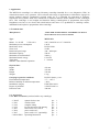
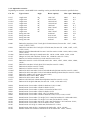
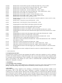
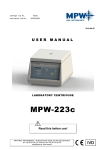
centrifuge - Cat. No.: 10223e user manual - Cat. No.: 20223e/ENG 2012-11-26 USER MANUAL LABORATORY CENTRIFUGE MPW-223e Read this before use! MPW MED. INSTRUMENTS, 46 Boremlowska Street, 04-347 Warsaw/Poland tel.+48 22 610 81 07 (service), fax +48 22 610 55 36 [email protected], www.mpw.pl 2 Contents 1. Application. 2. Technical data. 2.1. Accessories. 2.1.1. Basic accessories. 2.1.2. Optional accessories. 2.2. Exploitation materials. 3. Installation. 3.1. Unpacking of the centrifuge. 3.2. Location. 3.3. Connection to mains. 3.4. Fuses. 4. Description of the centrifuge. 4.1. General description. 5. Safe working conditions. 5.1. Operating personnel. 5.2. Guarantee period and operation life. 5.3. Safekeeping period. 5.4. Hints on centrifuging. 5.5. Hazards and precautions. 6. Operation of the centrifuge. 6.1. Service elements. 6.2. Mounting of the rotor and accessories. 6.3. Construction and safety measures. 6.4. Drive. 6.5. Data setting and read-out. 6.6. Controls. 6.7. Safety devices. 6.7.1. Cover lock. 6.7.2. Rest state check. 6.7.3. Unbalanced load checking system. 3 7. Description of the centrifuge operating elements. 7.1. Control panel 7.2. Switching the centrifuge on. 7.2.1. Selection of the program. 7.2.2. Start of the program. 7.2.3. Emergency stop. 7.2.4. End of the centrifuging. 7.2.5. Programming. 7.3. Mathematical relations. 7.3.1. RCF - relative centripetal force. 7.3.2. Nomogram of relationship - rotational speed/centrifuging radius/RCF 7.3.3. Maximum load. 8. Cleaning, disinfection, maintenance. 8.1. Cleaning of the centrifuge. 8.2. Cleaning of the accessories. 8.3. Sterilization and disinfection of the rotating chamber and accessories. 8.4. Lubrication. 8.5. Glass cracking. 9. Emergency conditions – service. 9.1. Troubleshooting. 10. Safety work. 10.1. Safety work inspection procedures. 10.2. Inspection procedures carried out by the operator. 11. Conditions of repairs. 12. Manufacturer’s data. 13. Information about Distributor. Annexes: Statement of conformity Declaration of decontamination (repair) Declaration of decontamination (return) 4 1. Application. The MPW-223e centrifuge is a table top laboratory centrifuge intended for in vitro diagnostic (IVD). Its construction ensures easy operation, safe work and wide range of applications in laboratories engaged in routine medical analyses, biochemical research works etc. It is intended for separation of mixtures, suspensions and systemic fluids into constituents of different densities under influence of the centrifugal force. This centrifuge is not biotight and therefore during centrifugation of preparations that require biotightness one has to use closed and sealed buckets and rotors. It is prohibited to centrifuge caustic, inflammable and explosive preparations in the centrifuge. 2. Technical data. Manufacturer: „MPW MED. INSTRUMENTS” SPÓŁDZIELNIA PRACY 46 Boremlowska Street, Warsaw/Poland Type: MPW-223e Mains: L1+N+PE V/Hz ±10% Maximum power consumption Interference level Noise level Rotational speed range Maximum capacity Maximum acceleration RCF Maximum kinetic energy Time range SHORT - short duration operation 230 V 50/60 Hz or 115 V 50/60 Hz 120 W PN-EN-55011 50 dB 300 4000 rpm 500 ml 2504 x g 1536 Nm 1 99 min Physical data: Depth Width Height Weight 435 mm 355 mm 270 mm 13 kg Centrifuge operation conditions: Environmental temperature Relative humidity at ambient temperature Installation category Degree of pollution Protection zone PN-EN 61010-1 p.1.4.1. +2 +40 C 80% II PN-EN 61010-1 2 PN-EN 61010-1 300 mm 2.1. Accessories. 2.1.1. Basic accessories (enclosed with every centrifuge). - 17099T - 17201 - 17142 - 17162 - 17861 - 17866 - 17867 - 20223e/ENG spanner for the rotor vaseline 20ml complete clamp key for emergency lid opening fuses WTA-T 4 A 250 V power cord 230 V power cord 115 V (optionally) Operating Instruction pcs. pcs. pcs. pcs. pcs. pcs. pcs. pcs. 5 1 1 1 1 2 1 1 1 2.1.2. Optional accessories. Depending on customer’s need MPW-223e centrifuge can be provided with accessories specified below: Cat. No. Type of rotor Angle Rotor capacity Max. rpm Rmax[cm] 11237 11257 11329* 11332 11333 11486 11487 11502 12183 12193 12232 12485 Angle rotor Angle rotor Angle rotor Angle rotor Angle rotor Angle rotor Angle rotor Angle rotor Swing-out rotor Swing-out rotor Swing-out rotor Swing-out rotor 30o 45o 30 30 30 30 45 30 12x15 ml 4x30/25 ml 10x30/25 ml 12x30/25 ml 10x50 ml 24x15/10 ml 8x15 ml 30x15/10 ml 4x100 ml 8x15/10 ml 4x7x10/5 ml 4x50 ml 4000 4000 4000 4000 4000 4000 4000 4000 4000 4000 4000 4000 13080 13245 13246 13247 13249C 13250 13265 13266 13267C 13276 13329 Bucket for test tubes 15/10/7/6 ml (13/17x100/120 mm) for rotor No. 11237, 11486, 11487, 11502, 12193; Bucket for test tubes 10/6/5 ml (13/17x70/85 mm) for rotor No. 11486, 11487, 11237, 11502, 12193; Bucket 100 ml without thread for rotor 12183 for carriers 14186÷14190, 14024, 14181, 14192, 14224 Bucket 100 ml with cap for round carrier No. 14186÷14190, 14024, 14181, 14192 Hanger 2x15 ml with 2 buckets “Falcon” No. 13080 for rotors No. 12183; Bucket 12x5 ml for test tubes ( 13x81 mm) for rotor 12232; Bucket for rotor No. 12232 for round carriers No. 14169, 14235, 14238, 14239, 14240, 14242 ; Bucket for test tubes 5x5 ml (12x75/85 mm) for rotor No. 12485; Bucket 4x10 ml for rotor No. 12485; Bucket 2x15 ml for rotor No. 12485; Bucket 50 ml for test tubes 50/30/25 ml with thread ( 30x99 mm) for rotor No. 12485; Bucket 50 ml for test tubes 50/30/25 ml without thread ( 30x96 mm) for rotor No. 12485; Bucket for Arthrex ACP system for rotor 12183; Bucket 50 ml for rotor 14089, 14248; Bucket 50 ml for rotor 14089, 14248; Bucket 1x50/30/25 ml without thread (30x96 mm) for rotor No. 11333; Bucket 30/25 ml (25x100 mm) for rotor No. 11329, 11332 and 11257; 14024 14035 14036 14043 14071 14089 14082 14088 14169 14181 14186 14187 14188 Round carrier for test tubes 15050 for buckets 13182, 13184C; Round carrier for test tubes 15046 for bucket 13276; Round carrier for test tubes 13,5mm x 92 mm for bucket 13276 Round carrier for test tubes 15419 for bucket 13276 Round carrier for test tubes 15055, 15117 for bucket 13276 Round carrier for test tubes 15050 for buckets 13250, 13276, 13266, 13267C Round carrier for test tubes 7/5 ml (17.6/13.3 mm) for buckets No. 13080 and 13081; Round carrier for test tubes 7/5 ml (17.3/13 mm) for bucket No. 13080; Round carrier for test tubes 8x5 ml ( 13x81 mm) for bucket 13233 and rotor 12232; Round carrier for test tubes 15119 for bucket 13182, 13184C Round carrier 4x7 ml ( 13.1x100 mm) for bucket No. 13184; Round carrier 4x10 ml ( 16.1x100 mm) for bucket No. 13182, 13184C; Rubber cushion for test tubes 100/50/30/25 ml for bucket No. 13182, 13184C; 13081 13182 13184c 13195 13170 13233 6 11,9 11,9 12 9,6 11,7 11,7 11,5 13,3 13,8 14 12,9 13,8 14189C 14190C 14192C 14196 14235 14238 14239 14240 14242 14248 14255 14256 15040 15046 15048 15050 15052 15053 15054 15055 15117 15118 15119 15120 15121 15419 Round carrier 50 ml “Falcon” ( 44.5/30 mm) for bucket No. 13182, 13184C; Round carrier 30/25 ml ( 44.5x25.5 mm) for bucket No. 13182, 13184C; Round carrier for test tubes 15116 for bucket 13182, 13184C Round carrier for bucket No. 13184 for bucket No. 13182, 13184C; Round carrier 12x5 ml ( 12x75 mm) for bucket No. 13233 and rotor No. 12232; Round carrier for test tube 15121 for bucket 13233 Round carrier for test tube 13,5mm x 75 mm d for bucket 13233 Round carrier for test tubes 15011, 15015, 15128 for bucket 13233 Round carrier for test tube 15016 for bucket 13233 Round carrier for test tubes 30/25 ml ( 29.8/26 mm) for bucket No. 13266, 13267C 13276, 13250, 13249C; Round carrier 7 ml ( 25/13 mm) for bucket No. 13329; Round carrier 15/10 ml ( 25/17 mm) for bucket No. 13329; Polypropylene test tube 100 ml with stopper ( 44.5x103 mm); Polypropylene test tube 14 ml with stopper ( 16.8x105 mm); Polypropylene test tube 15 ml “Nalgene” ( 16 x113 mm); Polypropylene test tube 15 ml “Falcon” ( 17/21x120 mm) for bucket No. 13080; Polypropylene test tube with conical bottom 50 ml (30/35x120 mm) for bucket No. 13249 and 13276; Polypropylene test tube 10 ml with stopper (16/19x100 mm) for bucket No. 13080; Polypropylene test tube 6 ml with cap ( 11.5x92 mm); Polypropylene test tube 30 ml with cap ( 24.8x100 mm) for bucket No. 13249 with reduction sleeve 14248 and for bucket No. 13329; Glass tube 25 ml ( 25x100 mm) for bucket No. 13249 with reduction sleeve No. 14248 and for bucket No. 13329; Glass tube 10 ml ( 16x100 mm) for bucket No. 13080; Glass tube 7 ml ( 12x100 mm) for carrier No. 14082 in bucket No. 13080; Glass tube 5 ml ( 12x75 mm) for carriers No. 14082, 14235 in bucket No. 13081; Polypropylene test tube 10 ml with stopper ( 17x70 mm) for bucket No. 13081 and carrier No 14234; Polypropylene test tube 5 ml (12x75 mm) for carrier No. 14082 in bucket No. 13081; * - while stocks last 2.2. Exploitation materials. Only proprietary elements listed in the equipment list shall be used in the centrifuge as well as centrifuge test-tubes with suitable diameter, length and strength. The use of test-tubes made by other companies shall be consulted with the manufacturer of the centrifuge. The centrifuge shall be cleaned and disinfected with agents used normally in the health care sector, such as Aerodesina-2000, Lysoformin 3000, Malseptol, Malsept SF, Sanepidex, Cutasept F. 3. Installation. 3.1. Unpacking of the centrifuge. Open the package. Take out the cardboard box containing the accessories. Take out the centrifuge from the package. Keep the package and packing materials at hand for possible transport at a later date. 3.2. Location. Almost all energy being supplied to the centrifuge is transformed into heat and then emitted to the environment. This is the reason why proper ventilation is essential. Ventilation ducts situated in the centrifuge have to be fully efficient. Moreover the centrifuge shall not be located near the radiators and shall not be subjected to direct sunlight. The table for the centrifuge shall be stable and shall have flat levelled table top. Safety zone has to be established around the centrifuge with the minimum radius of 30 cm. Under normal operating conditions ambient temperature shall not drop below 15 C or raise above 35 C. In the 7 case of changing location from a cold to warm one there will occur condensation of water inside the centrifuge. It is important then that sufficient time shall be allowed for drying the centrifuge prior to restarting of the centrifuge (minimum 4 hours). 3.3. Connection to mains. Supply voltage given on the rating plate has to be consistent with local supply voltage. MPW MED. INSTRUMENTS laboratory centrifuges are I safety class devices and are provided with the three-core cable of 2.53.2 m length with the plug resistant to dynamic loadings. Mains socket shall be provided with the safety pin. Neutral grounding of mains socket safety pin has to be verified by authorized services. This verification has to be carried out each time when mains socket is being replaced. It is recommended to install emergency cut-out that shall be installed far from the centrifuge, near the exit door from the room or outside the room. Supply voltage 230 V 50/60 Hz, optionally 115 V 50/60 Hz. 3.4. Fuses. The centrifuge has standard protection with the WTA-T 4A 250 V fuse situated in the plug-in socket and master switch unit at back wall of the centrifuge. 8 4. Description of the centrifuge. 4.1. General description. New generation of MPW MED. INSTRUMENTS laboratory centrifuges is provided with modern microprocessor control systems, very durable and quiet asynchronous brushless motors and accessories consistent with modern requirements. 5. Safe working conditions. 5.1. Operating personnel. MPW-223e Laboratory Centrifuge can be operated by laboratory personnel after getting acquainted with the Instruction Manual. User manual shall be always near the centrifuge. User manual must be constantly at hand!! 5.2. Guarantee period and operation life. Guarantee period for MPW-223e centrifuge amounts to minimum 24 months. Principles are specified in guarantee certificate. The service life of the centrifuge specified by the manufacturer amounts to 10 years. After termination of guarantee period it is necessary to carry out annual technical inspections of the centrifuge made by authorized service of manufacturer. The manufacturer reserves the right to make modifications at produced goods. 5.3. Safekeeping period. Maximum period of storage of not used centrifuge amounts to 1 year. After this period one should ask authorized service to carry out an inspection of the device. 5.4. Hints on centrifuging. 1. 2. 3. 4. 5. 6. 7. 8. 9. 10. 11. 12. 13. 14. 15. 16. 17. 18. Set the centrifuge in horizontal position on rigid base. Ensure safe location. Ensure free space around the centrifuge, within at least 30 cm. Ensure sufficient ventilation. Fix firmly the rotor on the motor shaft. Avoid unbalance. Load opposite buckets with the same accessories. Centrifugation of the test tubes of different dimensions. In principle it is possible to centrifuge test tubes of different dimensions, however it is absolutely necessary in such cases that opposite round carriers have to be the same. The test tubes shall be not only inserted symmetrically but round carriers and their hangers shall be equally loaded. It is not allowed to operate centrifuge with asymmetric loads applied to rotors and buckets. Load all places in rotors. Fill test tubes outside the centrifuge. Glass tubes shall be test tubes intended for centrifuges of proper strength enabling centrifugation with acceleration up to 5000 x g. Fill in the test tubes with the medium of the same weight, in order to protect the centrifuge against unbalance. Lubricate the rotor journal pins. Use only accessories kept in good condition. Protect equipment against corrosion using accurate preventive maintenance. Infectious materials could be processed in closed buckets only. It is prohibited to centrifuge explosive and inflammable materials. It is prohibited to centrifuge substances prone to reacting in result of supplying high energy during centrifugation. 9 5.5. Hazards and precautions. 1. 2. 3. 4. 5. 6. 7. 8. 9. 10. 11. 12. 13. 14. 15. 16. 17. 18. Prior to starting the trial of switching the centrifuge on, one shall read exactly all sections of this instruction in order to ensure smooth run of operation, avoiding damages of this device or its accessories. Centrifuge can be operated by laboratory personnel getting acquainted with the Instruction Manual. Centrifuge must not be transported with the rotor mounted on the motor shaft. One must use original rotors, test-tubes and spare parts only. In case of faulty operation of the centrifuge one shall ask for assistance of service of the MPW MED. INSTRUMENTS Company or its accredited representatives. It is prohibited to switch the centrifuge on if it is not installed properly or rotor is not fitted correctly. The centrifuge must not be operated in places where explosion hazard appears as it is not of explosion-proof make. It is prohibited to centrifugate materials which could generate inflammable or explosive mixtures when in contact with air. It is prohibited to subject to centrifugation toxic or infectious materials without taking proper safety measures (work in properly adapted rooms, personal safety equipment). Proper disinfection procedures have to be carried out when dangerous substances contaminated the centrifuge or its accessories. One must not open the cover manually – in emergency procedure, when rotor is still turning. One must not exceed limit load set by the manufacturer. Rotors are intended for fluids of average homogeneous density equal to 1.2 g/cm3 or smaller when centrifugation is carried out at maximum speed. When fluids of higher density shall be used, then it is necessary to limit the speed (see point 7.3.3 “Maximum load”). One must not to use the rotors, buckets and round carriers with symptoms of corrosion or other mechanical defects. One must not subject to centrifugation substances of high corrosion aggressiveness, which could cause material impairment and lower mechanical properties of rotors, buckets and round carriers. One must not use rotors and accessories not admitted by the manufacturer. It is permitted however to use commercial glass and plastic test tubes intended by manufacturer of these test tubes for centrifugation in laboratory centrifuges. It is distinct warning against using accessories not specified in the User manual. Cracking of test tubes not intended for centrifugation can result in dangerous unbalance. One must not carry out centrifugation with the rotors with taken off or not tight driven caps. One must not lift or shift the centrifuge during operation and rest on it. One must not stay in the safety zone within 30 cm distance around the centrifuge neither leave any things, e.g. glass vessels, within this zone. It is prohibited to put any things on the centrifuge. 10 6. Operation of the centrifuge. 6.1. Service elements 1 2 3 4 5 6 7 8 1. Cover of the centrifuge 2. Viewing port 3. Emergency cover release 4. Key for emergency lid opening 5. Control panel 6. Clamping bolt 7. Rotor 8. Motor shaft Drawing No. 1. General view. 6.1. Mounting of the rotor and accessories. 1. Connect the centrifuge to mains (master switch at back wall of the centrifuge). 2. Open the cover of the centrifuge pushing the pushbutton COVER. Prior to putting the rotor in one has to check if rotating chamber is free of impurities, e.g. such as dust, glass splinters, residues of fluids that must be taken away. 3. One shall release with special spanner clamp on the motor shaft and fit the rotor on the motor shaft driving it home on the cone. 4. Screw-in the bolt for fixing the rotor (clockwise) and screw it tightly home with the supplied 11 5. 6. 7. 8. 9. 10. 11. 12. 13. 14. spanner. Swing-out rotor have to be provided with the buckets in all seats. One should to remember that every buckets swings individually. Bucket suspension studs should be lubricated periodically with vaseline. In the case of rotors designed with the cover they must not be used without it. Rotor covers must be closed exactly. Rotor covers ensure smaller drags of the rotors, proper setting of the test-tubes and airtight sealing. One should use only buckets intended for selected types of the rotor – see p. 2.1. “Accessories”. Fill test tubes outside the centrifuge. Put on or screw the caps on vessels and rotors (when they have such). In the case of centrifuging in angle rotor, test tubes (buckets) have to be filled properly in order to avoid overflows. CAUTION: Centrifuge will tolerate small weight differences occuring during loading of rotors. However it is recommended to equalize vessels loads as much as possible in order to ensure minimal vibrations during operation. Maximum unbalance amounts up to 15 g. In order to prolong lifetime of the rotor and gaskets rotors shall be lubricated with the maintenance oil, while gaskets and threaded parts shall be lubricated with Vaseline (cat. no. 17201 – basic accessories). For replacement of the rotor one shall release clamping by several turns of the bolt and then using both hands grab the rotor at opposite sides taking it away from drive shaft by pulling it up. 6.2. Construction and safety measures. The centrifuge has rigid self-supporting structure. Housing is made of plastic while front is made of steel sheet. Cover is fixed on steel axles of hinges and from the front is locked with electromagnetic lock blocking possible opening during centrifugation. Bowl forming the rotation chamber is made of acid resistant steel sheet. 6.3. Drive. Drive constitutes brushless induction motor of low noise level, free of carbon brushes. This solution eliminated the danger of contamination the preparations with carbon dust. 6.4. Data setting and read-out. Data setting and read-out system forms hermetically closed keyboard with distinctly accessible operation points. Easily readable display signalling individual performed operations facilitates to operator programming of condition of the centrifuge. Operation of the centrifuge is simple and self-evident. 6.5. Controls. Microprocessor control system being used in the centrifuge ensures the following possibilities of setting of parameters of operation: - stepwise rotational speed selection within the range from 300 up to 4000 rpm every 100 rpm, - setting of the centrifugation time within the range from 1 up to 99 minutes, - selection of “SHORT” short duration operation setting for pre-programmed speed. 12 6.6. Safety devices. Apart from the above described passive devices and safety measures there exist as well active devices and elements as follows: 6.6.1. Cover lock. The centrifuge can be started only with properly closed cover. The cover can be opened only after stopping the rotor. In the case of emergency opening of the cover during operation the centrifuge will be immediately switched-off and the rotor will be braked until stopping completely. With opened cover, the drive is completely disconnected from power which makes it impossible to start the centrifuge. Emergency cover release In case of e.g. power failure there still exists possibility of manual opening of the cover. At right side of the casing there is situated small blanked hole, where one shall put key (cat. no.17162) or bar 2 mm and push it and cover opens by itself. CAUTION! Cover can be released and opened provided that rotor will be in rest state. 6.6.2. Rest state check. Opening of the centrifuge cover is possible only with the rotor in the state of rest. This state is being checked by the microprocessor which recognizes and signals the rest state prior to opening the cover with letter S (Stop). 6.6.3. Unbalanced load checking system. The centrifuge is equipped in unbalance sensor for protection. Drive is switched-off during acceleration or operation of the centrifuge when loads of opposite buckets or carriers in rotor are unbalanced and message U will be displayed. CAUTION!!! See paragraph 9.1./subparagraph 5. 13 7. Description of the centrifuge operating elements. Power switching ON/OFF is carried out with master switch situated on back of the centrifuge. All settings on the centrifuge are done by means of the control panel. Panel comprises control pushbuttons, displays and signalling LEDS. 7.1. Control panel. Control panel placed on front casing wall serves for controlling centrifuge operation. Control panel comprises the following elements: 1. Upper display field S: 4 digits (rpm) RCF 4 digits (x g) 2. Lower display field T: 4 digits (m/s) S (STOP), O (opened cover), U (unbalance) 3. Error signalling 3. Rotor status signalling STATUS COVER blinking – rotor rotates, not illuminated – rotor does not rotate. 4. Function key START 5. Function key STOP 6. Function key COVER ► ► Buzzer serves for signalling function recording and determination of the centrifuge status. START key serves for starting centrifugation program with parameters presented on display. ► STOP key serves for: - interrupting centrifugation program in any program phase and braking the rotor, - saving of preset SPEED and TIME centrifugation parameters. ► COVER key serves for opening of the cover. ► SPEED keys serve for speed programming. ► TIME keys serve for time programming. ► key serves for short duration operation. 14 7.2. Switching the centrifuge on. After switching power ON the control system calls recently implemented program and displays in relevant fields rotational speed, duration of centrifugation and cover opening status. Provided that rotor in the centrifuge is stopped, it is possible to open the cover by means of COVER key. Stopped rotor status is displayed as a S letter symbol in the display field. When this symbol is not already displayed, then one must wait till this rotor stops and the above mentioned symbol appears. 7.2.1. Selection of the program. Control panel can save 1 program preset by the user. Program acceptance consists in pushing STOP key. 7.2.2. Start of the program. After acceptance of the program and checking if rotor was mounted, centrifuge can be started with pushing START key, provided that cover is closed. 7.2.3. Emergency stop. At any time during centrifuging it is possible to interrupt the process and stop the rotor quickly with single pushing of STOP key. 7.2.4. End of the centrifuging. After termination of time of centrifugation preset in the program, braking follows. At the end of deceleration the rotational speed drops at slower rate in order to ensure soft settling of rotor carriers. Stopping is followed by buzzer signal and is displayed by S letter symbol. After pushing COVER pushbutton the cover opens and O symbol is displayed. 7.2.5. Programming. Programming mode is activated with pushing SPEED and TIME ( + ) ( - ) keys after selection of parameters of the program which one would like to save or change. Acceptance of preset parameters is done by pushing STOP key. One can save one program only. 15 7.3. Mathematical relations. 7.3.1. RCF – relative centripetal force. RCF acceleration is the acceleration generated by the rotor rotary motion acting upon tested product and it can be calculated according to the formula: RCF = 11.18 * r * (n/1000)2 where RCF [x g] r [cm] n [rpm] Depending on the distance of particles of the tested product from the axis of rotation one can find from above formula minimum RCF, average RCF or maximum RCF. On the basis of preset RCF value and given radius of the bottom in the bucket one can calculate from the formula the rotational speed to be set in the program of centrifuging. Selection of the time of sedimentation and the RCF value shall be carried out experimentally for a given product. Once every 100 rpm electronic circuit automatically calculates and displays averaged RCF value. 16 NOMOGRAM 7.3.2. Nomogram of relationship - rotational speed/centrifuging radius/RCF [r.p.m] Centrifuging radius [cm] R.C.F. (x "g") multiple of gravitational acceleration 50 20000 45 50000 40000 15000 14000 13000 12000 11000 10000 30000 9000 100000 40 35 Formula used for calculation of this nomogram : 2 R.C.F.= 11,18 * r * (n/1000) where : 30 29 28 27 26 25 24 23 22 21 20 19 A R.C.F. r n g multiple of gravitational speed centrifuging radius (cm) rotational speed (r.p.m.) gravitational acceleration - 10000 8000 6000 5000 4000 1500 1200 1000 800 16 600 500 400 15 14 300 13 200 Example of making use 150 120 100 80 of the nomogram: 11 10 60 50 40 A=14,4 cm B=4600 r.p.m. C=3400 x g 9 30 25 20 8 7000 15000 3000 2400 2000 18 17 12 8000 20000 6000 B 5000 4500 C 4000 3500 3000 2500 2000 1500 1400 1300 1200 1100 1000 900 800 700 600 500 15 7 6 5 n 1000 * r RCF 11,18 * r RCF 2 11 ,18 * n 1000 400 10 8 6 5 4 300 3 200 17 7.3.3. Maximum load. In order to avoid overloading of the rotor one shall observe maximum load which is recorded on every rotor. Maximum permissible load is reached when all test-tubes are filled with the fluid with 1.2 g/cm3 density. If density of the centrifugated liquid is higher than 1.2 g/cm3, then test-tubes could be filled only partially or one shall limit operation speed of the centrifuge that is being calculated from the formula: nperm = n max * 1,2 G = specific gravity 3 cm nmax - maximum rotational speed (RPM) nperm - permitted speed 8. Cleaning, disinfection, maintenance. CAUTION!!! Use safety gloves for operations specified below. 8.1. Cleaning of the centrifuge. Prior to start of cleaning and disinfection of the centrifuge one shall put the safety gloves on. For cleaning shall be used water with soap or other water soluble mild detergent. One should avoid corrosion inducing substances and aggressive substances. It is prohibited to use alkaline solutions, inflammable solvents or agents containing abrasive particles. 8.2. Cleaning of the accessories. In order to ensure safety operation one shall in regular way carry out periodical maintenance of the accessories. Manufactured rotors, buckets and round carriers have to withstand steady high stresses originated from the field of gravitation. Chemical reactions as well as corrosion (combination of variable pressure and chemical reactions) can cause corrosion or destruction of metals. Hard to observe surface cracks increase gradually and weaken material without visible symptoms. In the case of observation of surface damage, crevice or other change, as well the corrosion, given part (rotor, bucket, etc.) shall be immediately replaced. In order to prevent corrosion one has to clean regularly the rotor together with the fastening bolt, buckets and round carriers. Cleaning of the accessories shall be carried out outside of the centrifuge once every week or still better after each use. Then those parts shall be dried using soft fabric or in the chamber drier at ca. 50 C. Especially prone to the corrosion are parts made of aluminium. For cleaning them one should use very neutral agent of pH value within 68 range. It is forbidden to use alkaline agents of pH above 8. In this way substantially is increased useful service life and diminished susceptibility to corrosion. Accurate maintenance also increases service life and protects against premature rotor failures. Corrosion and damages resulting from insufficient maintenance could not be object of claims lodged against the manufacturer. 8.3. Sterilization and disinfection of the rotating chamber and accessories. All standard disinfecting agents can be used. The centrifuge and the equipment are made of different materials, which should be taken into account. Consider the temperature resistance of different materials when using steam for sterilisation. It should be mentioned that air-tight containers should be used for centrifuging, for example, infectious materials in order to prevent them from penetrating the centrifuge. 18 Containers and rotors can be autoclaved at 121o-124o C for 15 minutes at 215 kPa. The centrifuge shall be disinfected with disinfecting agents used normally in the health care sector, (for examples look at & 2.2.). The user is responsible for disinfecting the centrifuge properly, if a dangerous material has been spilled outside or inside the unit. Always wear protective gloves when performing the work described above. 8.4. Lubrication. The rotor pins shall be always lubricated with the Vaseline (cat. no. 17201 – basic accessories). In this way is ensured uniform deflection of the buckets and quiet centrifuge operation. 8.5. Glass cracking. In the case of glass cracking one shall wear safety gloves and all debris shall be accurately removed. Rubber inserts shall be exactly cleaned or possibly replaced. Otherwise one has to take into account the following possibilities: - Glass particles left in the rubber cushion (pad) will cause once more glass cracking. - Glass particles left in containers make impossible uniform deflecting of the buckets and round carriers resulting in unbalance. - Glass particles left in the rotor chamber cause metal abrasion because of strong air circulation. This dust will not only contaminate the centrifuge chamber, rotor, buckets, carriers and centrifuged material but will cause as well damages of surfaces of the accessories, rotors and the centrifuge chamber. For complete removal of glass particles and metal dust from the rotor chamber it is recommended to place on the bowl strip of vaseline (from the top down to bottom). Then rotor shall operate for several minutes at moderate speed. Glass and metal particles will collect on lubricated area and could be easily removed with the piece of cloth together with the grease. This operation can be repeated in case of need. 9. Emergency conditions – service. 9.1. Troubleshooting. Majority of faults could be cancelled by switching the centrifuge OFF and then ON. After switching the centrifuge ON shall be displayed parameters of the recently implemented program and buzzer signals consisting of four successive tones. In the case of short-duration power failure the centrifuge terminates cycle. Please find below the most frequent faults and their repair metods. 1. Lack of display and check buzzer: Is mains socket live? Is supply cable plugged into mains? Is input fuse good? Is master switch switched ON? The above was checked and still there is no display active and no check buzzer sound. 2. Centrifuge does not start START key pushing does not generate reaction or single tone only. Rotor stopping symbol S is not displayed yet. Cover opening symbol O is displayed. LED STATUS diode is blinking. Indications show a cycle in progress but the motor does not start Remedies: Check mains socket fuse. Plug correctly supply cable. Replace input fuse (rated data on rating plate). Switch ON power supply. Call service. Remedies Wait till rotor stops and the rotor stopping symbol is displayed Close cover. S symbol that means stop should be displayed. Centrifugation cycle in progress, push STOP key or wait till cycle ends. Switch power supply OFF/ON. If fault still persists then call service. 19 3. Programming function not active It is impossible to record parameter values to memory, last recorded program can not be recalled. Disturbances on displays possible too. 4. Centrifuge starts but does not accelerate E symbol displayed after stopping. Drive overload 5. Centrifuge starts and accelerate then decelerate and stops. Unbalanced load symbol U is displayed Offence of acceptable unbalance value of the rotor of test tubes. 6. One can not open the cover Rotor stopping S symbol not displayed yet, after pushing cover opening key single tone is audible. Nothing is displayed. Rotor stopping S symbol is displayed, but cover cannot be opened. Remedies Call service. Remedies Wait for 15 minutes and switch again after opening and closing the cover. Remedies Check: Rotor screw fixing, Symetrical load rotor with test tubes. Equalization of vessels loads. Remedies Rotor is still rotating. Wait for stopping of the rotor and displaying of the S symbol. Check the centrifuge power supply. Call service. 10. Safety work. 10.1. Safety work inspection procedures. From the point of view of operational safety the centrifuge has to be subjected to inspection carried out by authorized service engineer or especially trained experts at least once every year in the state of operational readiness. The reason for more frequent inspection could be for instance more frequent unbalance cases or corrosion inducing environment. Results of inspections, repairs and tests have to be recorded and kept on file. Operating Instruction shall be stored in the centrifuge use place. 10.2. Inspection procedures carried out by the operator. Operator has to pay special attention to the fact that the centrifuge parts important because of safety reasons are not damaged. This remark is specifically important for: 1. Motor suspension. 2. Motor shaft concentricity. 3. Fixing the pins in the bucket 4. Centrifuge accessories and especially structural changes, corrosion, preliminary cracks, abrasion of metal parts. 5. Screw joints. 6. Inspection of the rotor assembly. 7. Inspection of bioseals of the rotors if such are used. 20 11. Conditions of repairs. Manufacturer grants to the Buyer a guarantee on conditions specified in the Guarantee Certificate. Buyer forfeits the right to guarantee repair when using the device inconsistently with the Operating Instruction provisions, when damage resulted from the User's fault. Repairs should be carried out in authorized service workshops granted with the MPW Certificate. The centrifuge shall be sent to repair after decontaminating disinfection. Information about authorized service workshops could be obtained from the Manufacturer, i.e. 12. Manufacturer’s data. „MPW MED. INSTRUMENTS” SPÓŁDZIELNIA PRACY 46 Boremlowska Street 04-347 Warsaw, Poland tel. service fax +48 22 610 56 67 +48 22 610 81 07 +48 22 610 55 36 internet: e-mail: http://www.mpw.pl [email protected] 13. Information about Distributor. DISTRIBUTOR: 21 DECLARATION OF CONFORMITY Product Laboratory centrifuge Model MPW-223e Product classification on the basis of the Directive 98/79/EC Non classified to list A or B and not for self-testing Product complies with the requirements: · Directive 98/79/EC (IVD), including the requirements of harmonised standards: PN-EN ISO 13485:2012 PN-EN ISO 18113-3:2011 PN-EN ISO 13485:2012/AC:2013-03 PN-EN 61010-2-101:2005 PN-EN 13612:2006 PN-EN 61326-2-6:2013-08 PN-EN ISO 14971:2012 PN-EN ISO 62366:2008 · selected harmonized standards of Directive 2006/95/EC (LVD): PN-EN 61010-1:2011 PN-EN 61010-2-020:2008 · Directive 2004/108/WE (EMC) · standard PN-EN ISO 15223-1:2012 „MPW MED. INSTRUMENTS” SPÓŁDZIELNIA PRACY Warsaw, 46 Boremlowska Street Quality policy in line with ISO 9001:2008 Certifying authority Warsaw, 13.11.2014 nr 10.223e.03 DECLARATION OF DECONTAMINATION In order to protect our employees please fill out the declaration of decontamination completely before sending centrifuge to the manufacturer (repair). 1. 2. Device ─ type: ……………………………………………………………………………………… ─ serial No.: ……………………………………………………………………………………… Description of decontamination (see user manual) ……………………………………………………………………………………………………………………………………………… ……………………………………………………………………………………………………………………………………………… ……………………………………………………………………………………………………………………………………………… ……………………………………………………………………………………………………………………………………………… 3. 4. Decontamination carried out by: ─ name: ………………………………………………………………………… Date and signature ………………………………………………………………………… DECLARATION OF DECONTAMINATION In order to protect our employees please fill out the declaration of decontamination completely before sending centrifuge to the manufacturer (return). 5. 6. Device ─ type: ……………………………………………………………………………………… ─ serial No.: ……………………………………………………………………………………… Description of decontamination (see user manual) ……………………………………………………………………………………………………………………………………………… ……………………………………………………………………………………………………………………………………………… ……………………………………………………………………………………………………………………………………………… ……………………………………………………………………………………………………………………………………………… 7. 8. Decontamination carried out by: ─ name: ………………………………………………………………………… Date and signature …………………………………………………………………………