1
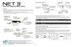
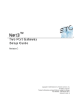
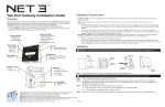
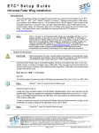
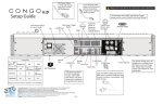
RS-232 Serial Port
I/O Gateway Setup Guide
Overview
This Setup Guide will guide you through the setup of the Net3 I/O Gateway including hardware, electrical and data
connections. Software configuration of your gateway is covered separately and relates specifically to the software
versions that may be running in the gateways.
• For Net3 configuration, please refer to the Gateway Configuration Editor (GCE) Online Help System.
• For use on ETCNet2 systems, use the ETCNet2 Network Configuration Editor (NCE) User Manual which includes
information about the Net3 gateways running in ETCNet2 mode.
NOTE:
PoE (IEEE 802.3af)
10/100Mbps data speeds
Auto-sensing
Auto-negotiation
RJ45 and etherCON compatible
Power Indicator
• Solid blue LED
indicates power
14
2
15
16
4
17
5
Reset Button
• hard reboot
18
6
I/O
Activity Indicator
• Solid green LED indicates
network connection.
• Flashing LED indicates
network activity
LCD
• Displays gateway status
and configuration data
3
4
5
6
7
8
9
Connection
unused
RS232-TX
RS232- R X
unused
ISO-ground
RS232-DSR
RS232- CTS
RS232- RTS
unused
A straight through cable is required to connect to a computer (use DTE pinout). Connecting to many remote serial
products requires a cross-over cable (use DCE pinout).
Analog Input DB25 Connector Pinout
1
3
Push
2
Pin
1
2
3
4
5
6
7
8
9
The analog input port is used to accept external contact closures and/or analog 0 - 10Vdc input (depending on software configuration) and send
them as Net3/ACN Ethernet messages to a networked control console or other ACN device. This port requires an external 10Vdc power supply to
operate. In On/Off mode (contact closure), the gateway supplies +5Vdc to the circuit through each input pin.
Menu Button
• Activates the LCD backlight
• Advances display pages
1
Analog Input Port
Ethernet Connection
•
•
•
•
•
RS-232 Pinout
At the most basic level, the serial port on the I/O Gateway acts as a converter between standard
RS-232 serial strings of information and a Net3/ACN equivalent that is sent over Ethernet. This
allows a control console, or other ACN device, to have a remote serial port and to extend the
normal distance limitations of serial communications. The I/O Gateway does not act on this serial
communication, but acts as a bridge between RS-232 and Ethernet.
The serial property options available are (default settings are in bold):
• 9600, 14400, 19200, 28800, 38400, 57600 and 115200 Baud
• 7 or 8 data bits
• None, Even or Odd for Parity
• 1 or 2 Stop Bits
• None, Xon/Xoff, Hardware are the Flow Control options
19
7
20
8
21
9
10
11
12
13
22
23
24
25
Pin
1
2
3
4
5
6
7
8
9
10
11
12
13
Connection
Analog In #01
Analog In #02
Analog In #03
Analog In #04
Analog In #05
Analog In #06
Analog In #07
Analog In #08
Analog In #09
Analog In #10
Analog In #11
Analog In #12
Analog In #13
Pin
14
15
16
17
18
19
20
21
22
23
24
25
Connection
Analog In #14
Analog In #15
Analog In #16
Analog In #17
Analog In #18
Analog In #19
Analog In #20
Analog In #21
Analog In #22
Analog In #23
Analog In #24
Analog In-Ground
Example circuit for Analog inputs
Example for Digital Input (on/off)
Choose your input connections based on your own system
+5 Vdc Input
(input/pins 1 - 24)
Motion Sensor
on
common
Connect to input/pin 1
Contact Closure
Connect to input/pin 2
(for example to trigger a remote macro)
Contact Closure
Ground (pin 25)
(for example to trigger
a remote macro)
Connect to input/pin 3
Variable resistor
(to provide 0-10v feedback)
common
Connect to ground/pin 25
+10v
External Power Supply
Relay Outputs
Analog Input Port
• Analog (0-10Vdc)
• Digital (on/off)
Strain Relief
• strain relief clip for
dc power cable
RS232 Serial Port
• DB-9 port
• DCE pinout
•
•
•
•
IO/OI
Analog In
10 Vdc Max
8-28Vdc
Positive tip
3.5mm barrel
5 Watts usage
Power Indicator
• Solid blue LED
indicates power
Relays 1-8
SERIAL
When choosing your connections (normally open versus normally closed) to the relay outputs, be sure to consider the default or powered off state
of the relay and how your connected device will react when the I/O Gateway is powered off or reset.
For example, if your device will activate with a closed circuit, don’t choose a normally closed connection and keep it open using a command from a
controlling Ethernet based device. This choice could result in your device activating at an unanticipated time during a software update or when the
gateway is not powered. You should choose the normally open connection instead as it doesn’t activate unless it is specifically directed to do so.
DC Power Input
Relays 9-16
30Vdc, 1A Max
Activity Indicator
Relay Outputs
• Normally open contacts
• Normally closed contacts
• Max. Switching of 1A@30Vdc
Grounding
Post
• Solid green LED indicates
network connection.
• Flashing LED indicates network
activity
Corporate Headquarters 3031 Pleasant View Road, P.O. Box 620979, Middleton, Wisconsin 53562-0979 USA Tel +608 831 4116 Fax +608 836 1736
London, UK Unit 26-28, Victoria Industrial Estate, Victoria Road, London W3 6UU, UK Tel +44 (0)20 8896 1000 Fax +44 (0)20 8896 2000
Rome, IT Via Pieve Torina, 48, 00156 Rome, Italy Tel +39 (06) 32 111 683 Fax +44 (0) 20 8752 8486
Holzkirchen, DE Ohmstrasse 3, 83607 Holzkirchen, Germany Tel +49 (80 24) 47 00-0 Fax +49 (80 24) 47 00-3 00
Hong Kong Rm 1801, 18/F, Tower 1 Phase 1, Enterprise Square, 9 Sheung Yuet Road, Kowloon Bay, Kowloon, Hong Kong Tel +852 2799 1220 Fax +852 2799 9325
Service: (Americas) [email protected] (UK) [email protected] (DE) [email protected] (Asia) [email protected]
Web: www.etcconnect.com Copyright © 2012 ETC. All Rights Reserved. Product information and specifications subject to change.
Page 1 of 2
4263M2200 Revision D 2012-05
Relay Outputs 1-8 DB25 Connector Pinout
Pin Connection
1 Normally Closed #1
Common #1
2
Normally Open #1
3
Normally Closed #2
4
Common #2
5
6 Normally Open #2
7 Normally Closed #3
8 Common #3
9 Normally Open #3
10
Normally Closed #4
Common #4
11
Normally Open #4
12
Normally Closed #5
13
NOTE:
Pin
14
15
16
17
18
19
20
21
22
23
24
25
Connection
Common #5
Normally Open #5
Normally Closed #6
Common #6
Normally Open #6
Normally Closed #7
Common #7
Normally Open #7
Normally Closed #8
Common #8
Normally Open #8
unused
1
2
3
4
5
6
7
8
9
10
11
12
13
Each relay supports a maximum of 1.0A at 30Vdc.
Relay Outputs 9-16 DB25 Connector Pinout
14
15
16
17
18
19
20
21
22
23
24
25
Pin
1
2
3
4
5
6
7
8
9
10
11
12
13
Connection
Normally Closed #9
Common #9
Normally Open #9
Normally Closed 10
Common #10
Normally Open #10
Normally Closed #11
Common #11
Normally Open #11
Normally Closed #12
Common #12
Normally Open #12
Normally Closed #13
Pin
14
15
16
17
18
19
20
21
22
23
24
25
Connection
Common #13
Normally Open #13
Normally Closed #14
Common #14
Normally Open #14
Normally Closed #15
Common #15
Normally Open #15
Normally Closed #16
Common #16
Normally Open #16
unused
Optional Accessories
Power Up Using DC Power
When using an external power supply, the gateway must be connected to a network before being powered.
Rack Mount Kit (4260K1001)
The Net3 Gateway Rack Mount kit is capable of holding up to two Net3 gateways for mounting into a standard 19” rack enclosure. If you only
need to mount one unit, a blanking plate is provided with the kit. This blanking plate can be installed on either side of the rack mount bracket.
Menu Structure
The Net3 I/O Gateway has a one button interface. Pressing the [Menu] button repeatedly cycles through the menu, displaying
related data. On certain menu items you are prompted to press and hold the [Menu] button for a period of 5 seconds to
change a state or setting.
FOH_Box1
Analog Input 1
0.00 Volts - 00%
Hanging Hardware Kit (4260K1005)
The Net3 Hanging Hardware kit allows pipe mounting of a Net3 Gateway in a variety of orientations. You can vary the way the U-bolt (or
c-clamp) attaches to the bracket and the way the bracket mounts to the gateway. The bracket attaches to any edge on the bottom of your
gateway.
•
displays either the gateway name or the “IP Address”.
•
displays “Analog Input” if the gateway is configured for Analog “0 to 10 Volts” input mode or displays “Contact Input” if
the gateway is configured for “On / Off” input mode. Each of the 24 inputs are displayed on their own menu page.
when in “0 to 10 Volts” input mode, 0.00 Volts displays the voltage measured at the contact or when in “On / Off” input mode the
display will show “Open” or “Closed”.
•
IP Address
10.101.50.102
•
displays the current IP address of the gateway.
Subnet Mask
255.255.0.0
•
displays the current Subnet Mask of the gateway.
Gateway IP
10.101.50.102
•
displays the current IP address for a network router (or the gateway’s own IP address).
Gateway Version
v1.0.0.9.0.64
•
displays the version number of the software currently running on this device.
Hold button 5 sec to
Download Software
•
software is retrieved from the current TFTP update server .
Hold button 5 sec to
Factory Defaults
•
Restoring defaults will cause the gateway to reset all settings to the factory defaults.
Help from ETC Technical Services
If you experience difficulty during setup or installation of the Net3 gateway, additional information is available from
www.etcconnect.com, or by contacting ETC Technical Services at your local office listed on the bottom of page 1.
Page 2 of 2