1
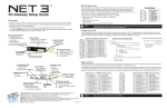
Net3 ™ Two Port Gateway Setup Guide Revision C C o p y r i g h t © 2 0 0 9 E le c tr o n i c T h e a t r e C o n t r o l s , I n c . All Rights reserved. P r o d u c t in f o r m a t i on a n d s p e c i f i c a t i o n s s u bj e c t t o c h a n g e . Part Number: 4261M2200 Rev C R e le a s ed : 2 0 0 9 - 0 4 E T C p e r m i t s t h e r e p r od u c ti o n o f m a te r i a l s i n t h i s m a n u a l on l y f o r n o n - c o m m e r c ia l p u r p o s e s . A l l o th e r r i g h t s a r e reserved by ETC. E T C intends this do cument, w het her pr in ted or electr oni c, to be pr ovided in it s en tir ety. Table of Contents Introduction. . . . . . . . . . . . . . . . . . . . . . 1 Completely New, Totally Familiar . . . . . . . . . . . . . . . . . . . . . . . . . . 1 Using this Manual . . . . . . . . . . . . . . . . . . . . . . . . . . . . . . . . . . . . . . 1 Help from ETC Technical Services . . . . . . . . . . . . . . . . . . . . . . . . . 2 Section 1: Gateway Hardware . . . . . . . . . . . . . . . . . . . 3 Front Panel Layout . . . . . . . . . . . . . . . . . . . . . . . . . . . . . . . . . . . . . 3 Gateway Bottom View . . . . . . . . . . . . . . . . . . . . . . . . . . . . . . . . . . . 3 Data & Power Connections . . . . . . . . . . . . . . . . . . . . . . . . . . . . . . . 3 Section 2: Installing the Gateway. . . . . . . . . . . . . . . . . 4 DMX Basics & Pin-outs. . . . . . . . . . . . . . . . . . . . . . . . . . . . . . . 5 RDM Basics . . . . . . . . . . . . . . . . . . . . . . . . . . . . . . . . . . . . . . . 5 Appendix A: Specifications . . . . . . . . . . . . . . . . . . . . . . . 6 Net3 Two Port Gateway Control Features. . . . . . . . . . . . . . . . . . . . Net3 Two Port Gateway Specification . . . . . . . . . . . . . . . . . . . . . . . General . . . . . . . . . . . . . . . . . . . . . . . . . . . . . . . . . . . . . . . . . . . Network. . . . . . . . . . . . . . . . . . . . . . . . . . . . . . . . . . . . . . . . . . . DMX Connections. . . . . . . . . . . . . . . . . . . . . . . . . . . . . . . . . . . Mechanical . . . . . . . . . . . . . . . . . . . . . . . . . . . . . . . . . . . . . . . . Electrical . . . . . . . . . . . . . . . . . . . . . . . . . . . . . . . . . . . . . . . . . . 6 6 6 6 6 7 7 E T C ®, E m p h a s i s ®, U n i s o n ®, L i g h t M a n a g e r ™ , O b s e s s i o n ® I I , E T C N e t 2 ™ , a n d E D M X ™ , S m a r t B a r ™ , S m a r t M o d u l e ™ a r e e i th e r r e g i s t e r e d t r a d e m a r k s o r t r a d e m a r k s o f E l e c t r o n i c T h e a t r e C o n t r o l s , I nc . i n t h e U n i t e d S t a t e s a n d o t h e r c o u n t r i e s . A l l o th e r t r a d e m a r k s , b o t h m a r k e d a n d n o t m ar k e d , a r e t h e p r o p e r ty o f t h e i r r e s p e c t iv e o w n e r s . i ii Introduction Congratulations on your purchase of an industry leading ETC Net3™ network device. This manual will guide you through the setup of the hardware, electrical and data connections of this Gateway. It does not cover any of the software modes and configuration. This is covered separately and tied to the software versions that may be running in these Gateways. Please use the ETCNet2 NCE v4.1 User Manual which includes information about the Net3 DMX Gateways running in ETCNet2 mode. For Net3 (ACN) configuration, please refer to the Gateway Configuration Editor (GCE) User Manual. Completely New, Totally Familiar The Net3 Two Port Gateway is new from the ground up with strong family resemblance to the Net3 Four Port Gateway. For that matter, the Two Port and the Four Port Gateways run the same software and when in ETCNet2 mode, they are configured via NCE (Network Configuration Editor). Using this Manual In order to be specific about where features and commands are found, the following naming and text conventions will be used throughout this manual: • References to other parts of the quick guide are indicated in italics. When viewing this setup guide electronically, click on the reference to jump to that section in the document. Note: Notes are helpful hints and information that is supplemental to the main text. CAUTION: Caution statement indicates situations where there may be undefined or unwanted consequences of an action, potential for data loss or an equipment problem. CAUTION: Caution statement indicates situations where ESD (Electro-Static Discharge) may damage equipment. Special precautions should be taken to keep your self grounded to avoid damaging the equipment. WARNING: A Warning statement indicates situations where damage may occur, people may be harmed, or there are serious or dangerous consequences of an action. WARNING: RISK OF ELECTRIC SHOCK! This warning statement indicates situations where there is a risk of electric shock. Please email comments about this manual to: [email protected] 1 Help from ETC Technical Services If you are having difficulties, your most convenient resources are provided in this user manual. To search more widely, try the ETC website at www.etcconnect.com. If none of these resources is sufficient, contact ETC Technical Services directly at one of the offices identified below. Americas Electronic Theatre Controls Inc. Technical Services Department 3031 Pleasant View Road Middleton, WI 53562 800-775-4382 (USA, toll-free) +1-608 831-4116 [email protected] Asia Electronic Theatre Controls Asia, Ltd. Technical Services Department Room 1801, 18/F Tower 1, Phase 1, Enterprise Square 9 Sheung Yuet Road Kowloon Bay, Kowloon, Hong Kong +852 2799 1220 [email protected] 2 United Kingdom Electronic Theatre Controls Ltd. Technical Services Department 26-28 Victoria Industrial Estate Victoria Road, London W3 6UU England +44 (0)20 8896 1000 [email protected] Germany Electronic Theatre Controls GmbH Technical Services Department Ohmstrasse 3 83607 Holzkirchen, Germany +49 (80 24) 47 00-0 [email protected] Net3 Two Port Gateway Setup Guide Section 1: Gateway Hardware Front Panel Layout Blue LED • On indicates power Green LED • On indicates network connection • Flashing indicates network activity LCD display. The exact content changes by mode and software version but generally contains information about status, configuration and the software that is currently active in the Gateway The LCD button activates the backlight (depending on the mode) as well as advances through display pages Reset button to hard reboot the Gateway (this button is recessed) Gateway Bottom View View: Looking up at the bottom of the Two Port Gateway Port #1 Screw to secure or remove Two Port Gateway from it’s mounting plate Port #2 Available with a pair of DMX Out (XLR Fem) connectors or a pair of DMX In (XLR Male) connectors Screw to secure or remove Two Port Gateway from it’s mounting plate Data & Power Connections The Net3 Two Port Gateway is powered by either PoE (Power Over Ethernet 802.3af) or via an external dc power supply. The external power supply connects via a 2-pin header provided on the rear PCB. The gateway accepts between 8 and 28Vdc via this input. The Ethernet network connection is via an RJ45 jack on the rear PCB and supports PoE, auto-sensing, auto-negotiation 10/100Mbps data speeds. Though not advised to connect power via both PoE and the external dc input at the same time, the gateway will function normally and use the power from the external dc input instead of from PoE. Gateway Hardware 3 Section 2: Installing the Gateway WARNING: RISK OF ELECTRIC SHOCK! Power must be removed from the Gateway before removing the unit or servicing the unit. With power disconnected from the Gateway, you can install or remove the unit from its enclosure. When using PoE (Power Over Ethernet), don’t patch this unit prior to installation. Use the provided screws to secure the mounting bracket to the enclosure. Note that this same bracket works for in-wall back boxes, surface-mount boxes and portable enclosures. 1 2 Make the power and data connections. This may consist of only plugging in the Ethernet connection if you are using PoE or both power and Ethernet connections. Line up and insert the top alignment pins first, then... 4 J9 J8 + - Near-side gateway cover is not shown for clarity. 12V PWR This dc input supports 8-28Vdc. 3 4 10/100 ETHERNET ON ON S1 S2 Set the DMX termination if necessary via S1 and S2. S1 controls the termination for Port 2, and S2 controls the termination for Port 1. These switches are defaulted to on for every module and it is very rare that you would ever need to disable DMX termination on this unit. 5 ...swing the bottom of the gateway into place and tighten the screws on either side of the bottom of the unit. Net3 Two Port Gateway Setup Guide DMX Basics & Pin-outs The Net3 Two Port Gateway sends and receives DMX 512 control signals. The unit is can contain a pair of 5-pin XLR DMX input connectors or a pair of 5-pin XLR DMX output connectors. DMX cables should be acceptable for DMX data transmission (not microphone cable) and should follow the standard pinout. The optional secondary data pair is not used by the Net3 Two Port Gateway. DMX512 Pinout for five-pin XLR Connectors Female Pin# Use Male 1 Common (Shield) 2 Data – Push 3 Data + 4 not connected 5 1 1 5 5 not connected 4 2 3 4 2 3 The DMX network supports up to 32 devices connected to each DMX line. Termination is required for all DMX networks and belongs at the beginning (source) of a DMX network and with the last device physically connected device in the chain. A pair of compact switches (S1 & S2) located behind the DMX connectors on the rear PCB in each unit is provided to enable and disable DMX termination. These switches are defaulted to “on” for every gateway. The most common reason to disable this termination is if you wanted to do a “touch and go” connection. “Touch and go” means that you land DMX wiring on the connector for the gateway, and continue to another DMX device. It is unlikely that this would be done with this gateway. RDM Basics Net3 Gateway software now supports Remote Device Management (RDM) protocol. By default, RDM is not enabled on Net3 Gateways. To enable RDM on the Net3 Gateway, Net3 Gateway Configuration Editor (GCE) is required. Please see the GCE help files for more information on activating RDM on your Net3 Gateways. About RDM Remote Device Management (RDM) is a protocol enhancement to DMX512 that allows bi-directional communication between a lighting system controller and attached RDM-compliant responder devices over a standard DMX line. This protocol allows configuration, status monitoring, and management of these devices. An RDM Controller is the device that initiates communication with one or more RDM Responder devices. Examples of controllers are ETC's Net3 DMX/RDM 2-Port and 4-Port Gateways and RDM-enabled consoles. An RDM Responder is the device that replies to communication from a controller. Examples of responders are RDM-enabled edge devices such as gel scrollers, dimmers, and moving lights. Net3 DMX/RDM Gateways support 32 RDM devices per port, just like DMX devices. Compliant DMX512 and DMX512-A devices (non-RDM devices) are completely functional when RDM is present. RDM was developed by the ESTA Technical Standards and can be referenced as ANSI/ ESTA E1.20. Installing the Gateway 5 Appendix A: Specifi cations N e t 3 T w o P o r t G a t e w a y C o n tr o l F e a tu r e s • Distributes DMX over Ethernet • Supports ETCNet2 and Net3/ACN protocols • Distributes DMX data to any input/output device such as dimmers, scrollers, moving lights and DMX consoles • Modular DMX/RDM port design allowing easy configuration of port connector type and replacement • DMX512 via XLR 5-pin Male, XLR 5-pin Female connectors • LCD screen for labeling, status and configuration indicators • LED power and network indicators • Supports Power over Ethernet (PoE) and an external DC power supply • Versatile compact size • Configurable via Network Configuration Editor software (NCE) or directly through ACN Net3 Two Port Gateway Specification General • USITT DMX512/512A and ESTA ACN standards supported • Supports ETCNet2 and Net3/ACN protocols • ETL/cETL approved (Tested to UL Standards by ETL) Networ k • Complies with IEEE 802.3i for 10BASE-T, 802.3u for 100BASE-TX and 802.3af for Power over Ethernet specifications • Data transport utilizes TCP/IP suite of protocols • Distributes DMX over Ethernet to any input/output device such as dimmers, scrollers, moving lights • 2048 DMX In or DMX Out channels • Configurable to over 32,000 EDMX addresses (Running ETCNet2 software) DMX Connections 6 • 2 DMX ports • Switch for DMX termination (internal access only) • Connector options include: • Two XLR 5-Pin Male DMX input connectors • Two XLR 5-Pin Female DMX output connectors Net3 Two Port Gateway Setup Guide Mechanical • Fits in standard 2-gang masonry deep back box • Fabricated of 16-gauge steel, finished in fine-texture, scratch-resistant, black powder coat • 4.875” x 5.00” x 1.90” / 124mm x 127mm x 48.2mm (W x H x D of gateway protruding out of a back box / enclosure) • Hanging Bracket for portable version allows mounting in many orientations (U-bolt option) • Single UTP Ethernet jack on rear PCB of unit • Backlit graphic LCD display for identification (soft-labeling) and status reporting: • Gateway identification (User-defined name, software version) • Network configuration (including IP address information) • DMX port configuration • DMX port status • Menu Button for backlight/paging control • Configuration done using Network Configuration Editor (NCE) • Power (blue) and Network present/activity (green) LED indicators on the front • Reset button for hard reset, forced reboot Electrical • Power consumption: 3.3 watts normal operation / 5 watt maximum. • Power Supply options include: • • 8 to 28Vdc external power • 48V IEEE 802.3af power over Ethernet (PoE) Optional Universal Power Supply available (ETC Part# PS313-F) 90-240VAC to 12Vdc @ 1.3A 7 Corporate Headquarters 3031 Pleasant View Road, P.O. Box 620979, Middleton, Wisconsin 53562-0979 USA Tel +608 831 4116 Fax +608 836 1736 London, UK Unit 26-28, Victoria Industrial Estate, Victoria Road, London W3 6UU, UK Tel +44 (0)20 8896 1000 Fax +44 (0)20 8896 2000 Rome, IT Via Ennio Quirino Visconti, 11, 00193 Rome, Italy Tel +39 (06) 32 111 683 Fax +39 (06) 32 656 990 Holzkirchen, DE Ohmstrasse 3, 83607 Holzkirchen, Germany Tel +49 (80 24) 47 00-0 Fax +49 (80 24) 47 00-3 00 Hong Kong Rm 1801, 18/F, Tower 1 Phase 1, Enterprise Square, 9 Sheung Yuet Road, Kowloon Bay, Kowloon, Hong Kong Tel +852 2799 1220 Fax +852 2799 9325 Service: (Americas) [email protected] (UK) [email protected] (DE) [email protected] (Asia) [email protected] Web: www.etcconnect.com Copyright © 2008 ETC. All Rights Reserved. Product information and specifications subject to change. 4261M2200 Rev C Released 2009-04