1
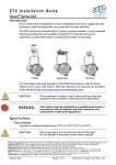
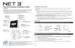
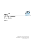
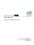
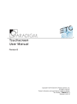
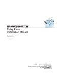
DMX Gateway Modules
DMX In Module
DMX RJ45 Module
(XLR 5-pin male)
(RJ45 8-pin female)
DMX Termination
• switch directly behind the
connector for convenience
Four-Port Gateway Setup Guide
• secures the module
in the gateway
• protects delicate
electronics
Overview
Pull Tab
This Setup Guide will guide you through the setup of the Net3 Four-Port DMX/RDM gateway including hardware, electrical and
data connections. Software configuration of your gateway is covered separately and relates specifically to the software versions
that may be running in the gateways.
• For Net3 configuration, please refer to the Gateway Configuration Editor (GCE) Online Help System.
• For use on ETCNet2 systems, use the ETCNet2 Network Configuration Editor (NCE) User Manual which includes information
about the Net3 DMX Gateways running in ETCNet2 mode.
Ethernet Connection
•
•
•
•
•
PoE (IEEE 802.3af)
10/100Mbps data speeds
Auto-sensing
Auto-negotiation
RJ45 and etherCON compatible
Menu Button
• Activates the LCD backlight
• Advances display pages
Retaining Screw
Protective Cover
Power Indicator
• Solid blue LED
indicates power
• for easy module removal
DMX Terminal
Strip Module
DMX Out Module
(XLR 5-pin female)
(8-pin male)
There are four different modules available for use in the Four-Port gateway: DMX Out (5-pin female), DMX In (5-pin male),
RJ45 (8-pin female for input or output) and DMX Terminal Strip (8-pin Weidmuller for input or output).
• The terminal strip module comes with ETC’s standard DMX termination preparation kit (part number 4100A1012) which includes instructions and
all parts required for installation. If you are connecting to Category 5 wire for DMX, request the DMX termination preparation kit with IDC
connectors from ETC (part number 4100A1013).
• The DMX RJ45 module can use a standard Category 5 cable to transmit DMX512 to other devices utilizing the same connector.
NOTE:
The DMX RJ45 module will not function as an Ethernet network port.
Push
Activity Indicator
Reset Button
• hard reboot
• Solid green LED indicates
network connection.
• Flashing LED indicates
network activity
LCD
• Displays gateway status
and configuration data
Any of these modules may be configured as DMX input or DMX output using configuration software. Additionally, there is a blanking plate for any
unused module bay.
WARNING:
RISK OF ELECTRIC SHOCK! Power must be removed from the gateway before removing any modules or covers to
service the unit.
With power removed from the Gateway, you can move and swap DMX modules as needed for required configuration or replacement.
Help from ETC Technical Services
Four Module Bays
• use any combination of modules
including the blank plate, DMX
Out (XLR Female), DMX In (XLR
Male), RJ45 and terminal strip
modules.
Strain Relief
• strain relief clip for
dc power cable
If you experience difficulty during setup or installation of the Net3 gateway, additional information is available from www.etcconnect.com, or by
contacting ETC Technical Services at your local office listed on the bottom left side of this document.
DC Power Input
•
•
•
•
DMX Basics and Pin-Outs
8-28Vdc
Positive tip
3.5mm barrel
5 Watts usage
Power Indicator
• Solid blue LED
indicates power
The Net3 Four-Port gateway sends and receives DMX512 control signals. This unit can contain up to four DMX ports in any combination
using 5-pin DMX input connectors, 5-pin DMX output connectors, RJ45 connectors, or terminal strip connectors. DMX cables must be
acceptable for DMX data transmission (not microphone cable) and connections should follow the standard pinouts per the charts below.
The optional secondary data pair is not used by the Net3 Four-Port gateway.
DMX512 Pinout for 5-pin XLR Connectors
Female (output)
Push
Grounding Post
• Solid green LED indicates
network connection.
• Flashing LED indicates network
activity
Corporate Headquarters 3031 Pleasant View Road, P.O. Box 620979, Middleton, Wisconsin 53562-0979 USA Tel +608 831 4116 Fax +608 836 1736
London, UK Unit 26-28, Victoria Industrial Estate, Victoria Road, London W3 6UU, UK Tel +44 (0)20 8896 1000 Fax +44 (0)20 8896 2000
Rome, IT Via Ennio Quirino Visconti, 11, 00193 Rome, Italy Tel +39 (06) 32 111 683 Fax +44 (0) 20 8752 8486
Holzkirchen, DE Ohmstrasse 3, 83607 Holzkirchen, Germany Tel +49 (80 24) 47 00-0 Fax +49 (80 24) 47 00-3 00
Hong Kong Rm 1801, 18/F, Tower 1 Phase 1, Enterprise Square, 9 Sheung Yuet Road, Kowloon Bay, Kowloon, Hong Kong Tel +852 2799 1220 Fax +852 2799 9325
Service: (Americas) [email protected] (UK) [email protected] (DE) [email protected] (Asia) [email protected]
Web: www.etcconnect.com Copyright © 2010 ETC. All Rights Reserved. Product information and specifications subject to change.
Page 1 of 2
4260M2200 Revision D 2010-01
5
1
4
2
3
DMX512 Pinout for Terminal Strip Connector
Use
Wire Color
Pin#
Use
Wire Color
Common
(shield)
1
Data 1 +
White/Orange
1
Common (shield)
Clear/Shield
Data -
2
Data 1 -
Orange
2
Data -
Black
3
not used
White/Green
3
Data +
Red
4
not used
Blue
4
unused
Use
1
2
Activity Indicator
DMX512 Pinout for RJ45 Connectors
Pin#
Pin#
3
Data +
4
unused
5
unused
Male (input)
Female
Push
1
5
2
4
3
1
8
Female
1
8
5
not used
White/Blue
5
unused
6
not used
Green
6
unused
7
Signal Common
White/Brown
7
unused
8
Signal Common
Brown
8
unused
75LBC182
S1
DMX Termination
Power Up Using DC Power
The DMX network supports up to 32 devices connected to each DMX line. Termination is required for all DMX
networks and belongs at the source (beginning) of a DMX network line and at the last device physically connected in
the line. A termination switch is located on each DMX module (yellow switch labeled Termination S1) to enable or
disable DMX termination. This switch is factory defaulted to “On” for every module. The most common reason to
disable termination is to support “touch and go” connections. “Touch and go” implies that you land DMX wiring on the
input connector for the gateway and continue to another DMX device (daisy-chain). This practice is uncommon when
using DMX gateways.
When using an external power supply, the gateway must be connected to a network before being powered.
Menu Structure
The Net3 Four-Port gateway has only a one button interface. Pressing the [Menu] button repeatedly cycles through the menu,
displaying mostly informational data. On certain menu items you are prompted to press and hold the [Menu] button for a period of 5
seconds to change a state or switch between operating modes. Both the ETCNet2 and Net3 menu structures are displayed below for
your convenience.
Replacing the DMX Transceiver Chip
Occasionally a DMX device can encounter an electrical surge that causes the DMX transceiver chip to fail. This DMX
chip (mfg# 75LBC182 / ETC# Z1458-F) is located under the cover next to the termination switch. As needed, you can
replace this DMX chip with another. It is best to remove this chip with an IC puller, if the tool is available to you.
RDM Basics
Net2 Menu
10.101.50.101
1 2 3 4
DMX Port 1 Output
EDMX Start: 1
Net3 gateway software supports Remote Device Management (RDM) protocol. By default, RDM discovery is not enabled on Net3
gateways. To enable RDM on the Net3 Four-Port gateway, use ETC’s Net3 Gateway Configuration Editor (GCE) software. Please see the
GCE online help files for more information on activating RDM on your Net3 gateways. RDM is not supported in Net2 mode.
Net3 Menu
1
FOH1
2 3
4
Port 1 Output
sACN 3/4:511
Port 1 RDM Enabled
Discovery On #12
About RDM
DMX Port 2 Output
EDMX Start: 513
Remote Device Management (RDM) is a protocol enhancement to DMX512 that allows bidirectional communication between a lighting
system controller and attached RDM-compliant responder devices over a standard DMX line. This protocol allows configuration, status
monitoring, and management of these devices.
An RDM Controller is the device that initiates communication with one or more RDM Responder devices. Examples of responders are
RDM-enabled edge devices such as color scrollers, dimmers, moving lights, and LED fixtures. RDM supports 32 RDM devices per-port,
just like DMX. Compliant DMX512 and DMX512-A devices (non-RDM devices) are fully functional when RDM is present. RDM was
developed by ESTA Technical Standards and can also be referenced as ANSI E1.20.
•
•
•
displays either the “gateway name” or the “IP Address”.
displays each port and its status ( = output, = input, no indication = disabled port
a port that flashes indicates it either has no patch data (EDMX or sACN) or no valid DMX is received on that port
•
displays the port priority mode (either “Output”, “Input Pri ***”, where *** indicates the port is set with per-address priority,
or “Input Pri 100” (where 100 is the priority value for that port). For Net2 mode, displays either “Input” or “Output”.
displays the patch information formatted as “universe”, “universe/address”, “universe/address:length”, “universe:length”
or “Custom (AIP)”. Net2 mode displays the EDMX start address.
•
•
•
displays the port RDM status (either “Enabled”, “Disabled”, or “Standby”). Can be enabled or disabled at the
gateway only if the port is set to “Output” mode by holding the [Menu] button for 5 seconds.
displays discovery status (either “Fast”, “On”, or “Off”).
Port 2 Input Pri***
Custom (AIP)
Port 2 RDM Disabled
DMX Port 3 Output
EDMX Start: 1025
Port 3 Input Pri 100
sACN 2:512
Port 3 RDM Disabled
Optional Accessories
DMX Port 4 Output
EDMX Start: 1537
Rack Mount Kit (4260K1001)
The Net3 Gateway Rack Mount kit is capable of holding up to two Net3
Gateways for mounting into a standard 19” rack enclosure. If you only
need to mount one unit, a blanking plate is provided with the kit. This
blanking plate can be installed on either side of the rack mount bracket.
Port 4 Output
sACN 1
Port 4 RDM Enabled
Discovery Off #0
Hanging Hardware Kit (4260K1004)
DMX Front Panel Kits
The Net3 Hanging Hardware kit allows pipe mounting of a Net3
Gateway in a variety of orientations. You can vary the way the
U-bolt (or c-clamp) attaches to the bracket and the way the
bracket mounts to the gateway. The bracket attaches to any
edge on the bottom of your gateway.
These kits provides front panel access to the DMX connectors on
a Net3 Four-Port Gateway when installed in an equipment rack.
You must use these kits in combination with one Net3 Four-Port
gateway and a Rack Mount Kit (4260K1001), not included.
4260K1002 - DMX out / 4260K1003 - 2 DMX in / 2 DMX out
A connector blanking plate (4260A3013) is required to cover an
unused connector opening when fewer than four DMX
connectors are required on the front panel.
The front panel connector bracket
replaces the rack mount kit
blanking plate.
IP Address
10.101.50.101
Static IP Address
10.101.50.107
•
•
displays either “Static” or “Dynamic” IP Address.
displays the current IP address of the gateway.
IP Subnet Mask
255.255.0.0
IP Subnet Mask
255.255.0.0
•
displays the current Subnet Mask of the gateway.
IP Gateway
10.101.50.101
IP Gateway
10.101.50.101
•
displays the current IP address for a network router (or the gateway’s own IP address).
TFTP Server
10.101.50.43
•
displays the current Trivial File Transfer Protocol (TFTP) server IP address for the gateway. The TFTP server is
typically an ETC console or computer running Gateway Configuration Editor (GCE) software.
Net2 Gateway Version
4.0.5.9.0.36
ACN Gateway Version
3.0.0.0.0.40
•
displays the version number of the software currently running on this device. If running in Net2 mode, “Net2
Gateway Version” displays along with the Net2 version number of software.
Hold button 5 sec to
Switch to ACN
Hold button 5 sec to
Switch to Net2
•
switch between ACN and Net2 modes. Net2 mode displays a limited menu selection displayed in the left
column of this menu structure.
Hold button 5 sec to
Reset Dynamic IP
•
if the IP mode is set in Gateway Configuration Editor (GCE) to Static, “Switch to Dynamic IP” displays. If the IP
mode is Dynamic, “Reset Dynamic IP” displays. Resetting the Dynamic IP erases the current IP from memory
and requests an IP from the DHCP address service after reboot.
Hold button 5 sec to
Download Software
Hold button 5 sec to
Download Software
•
software is retrieved from the current TFTP update server .
Hold button 5 sec to
Restore Defaults
Hold button 5 sec to
Restore Defaults
•
restoring defaults will cause the gateway to reset all settings to the factory defaults.
Mac Address
00:C0:16:00:00:1A
Page 2 of 2