1
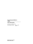
DEC FDDIcontroller/PCI
Installation
Order Number: EK-DEFPA-IN. C01
This manual describes how to install and verify the
operation of the DEC FDDIcontroller/PCI.
Revision/Update Information:
Digital Equipment Corporation
Maynard, Massachusetts
This is a revised
manual.
November 1994, January 1996, July 1996
Digital Equipment Corporation makes no representations that the use of its products
in the manner described in this publication will not infringe on existing or future
patent rights, nor do the descriptions contained in this publication imply the granting
of licenses to make, use, or sell equipment or software in accordance with the
description.
© Digital Equipment Corporation 1996.
All Rights Reserved.
Printed in Australia
DEC, DECconcentrator, DECconnect, DECnet, Digital, Digital UNIX, EtherWORKS,
GIGAswitch, PATHWORKS, ThinWire, OpenVMS, and the DIGITAL logo are
trademarks of Digital Equipment Corporation.
AT, IBM, PowerPC, and OS/2 are registered trademarks of International Business
Machines Corporation.
CompuServe is a registered trademark of CompuServe, Incorporated.
IEEE is a registered trademark of the Institute of Electrical and Electronics
Engineers, Inc.
Intel is a registered trademark of Intel Corporation.
MIPS is a registered trademark of MIPS Computer Systems, Inc.
NetWare and Novell are registered trademarks and NetWare SFT is a trademark of
Novell, Incorporated.
OSF/1 is a registered trademark of Open Software Foundation, Inc.
SCO, OpenServer, The Santa Cruz Operation, and UnixWare are trademarks or
registered trademarks of The Santa Cruz Operation, Inc.
UNIX is a registered trademark in the United States and other countries, licensed
exclusively through X/Open Company Ltd.
VINES is a registered trademark of Banyan Systems, Inc.
Windows is a trademark and Microsoft, MS–DOS, Windows for Workgroups, Windows
NT, and Windows 95 are registered trademarks of Microsoft Corporation.
All other trademarks and registered trademarks are the property of their respective
holders.
Contents
About This Manual . . . . . . . . . . . . . . . . . . . . . . . . . . . . .
vii
1 Introduction
Fiber-Optic SAS Adapter (DEFPA-AB) .
UTP SAS Adapter (DEFPA-UB) . . . . . .
Fiber-Optic DAS Adapter (DEFPA-DB)
UTP DAS Adapter (DEFPA-MB) . . . . .
LED Descriptions . . . . . . . . . . . . . . . . .
Software Description . . . . . . . . . . . . . .
Distribution Diskette . . . . . . . . . . . . . .
.
.
.
.
.
.
.
.
.
.
.
.
.
.
.
.
.
.
.
.
.
.
.
.
.
.
.
.
.
.
.
.
.
.
.
.
.
.
.
.
.
.
.
.
.
.
.
.
.
.
.
.
.
.
.
.
.
.
.
.
.
.
.
.
.
.
.
.
.
.
.
.
.
.
.
.
.
.
.
.
.
.
.
.
1–4
1–5
1–6
1–8
1–9
1–11
1–12
Checking Package Contents . . . . . . . . . . . . . . .
Preparing to Install the Adapter . . . . . . . . . . .
Verifying System and Software Requirements .
DOS Requirements . . . . . . . . . . . . . . . . . .
SCO OpenServer Requirements . . . . . . . . .
Configuring the Adapter . . . . . . . . . . . . . . . . .
Installing the Adapter . . . . . . . . . . . . . . . . . . .
Verifying the Installation . . . . . . . . . . . . . . . . .
Installing Device Drivers . . . . . . . . . . . . . . . . .
Installing DOS or OS/2 NDIS 2.01 Drivers
Installing the Windows 95 Driver . . . . . . .
Installing the Windows NT Driver . . . . . . .
Installing Novell NetWare Drivers . . . . . . .
Installing Netware Drivers . . . . . . . . .
.
.
.
.
.
.
.
.
.
.
.
.
.
.
.
.
.
.
.
.
.
.
.
.
.
.
.
.
.
.
.
.
.
.
.
.
.
.
.
.
.
.
.
.
.
.
.
.
.
.
.
.
.
.
.
.
.
.
.
.
.
.
.
.
.
.
.
.
.
.
.
.
.
.
.
.
.
.
.
.
.
.
.
.
2–2
2–4
2–4
2–5
2–5
2–6
2–6
2–9
2–10
2–10
2–11
2–11
2–12
2–12
2 Installation
iii
Using Custom Parameters for NetWare SFT
III . . . . . . . . . . . . . . . . . . . . . . . . . . . . . . . . . .
Loading and Viewing the Distribution Diskette
Installing the SCO OpenServer Driver . . . . . .
Network Management Information . . . . . . . . . . . .
Mac OS Information . . . . . . . . . . . . . . . . . . . . . . . .
Connecting to the Network . . . . . . . . . . . . . . . . . .
Connecting Fiber-Optic SAS Adapters . . . . . . .
Connecting Fiber-Optic DAS Adapters . . . . . . .
Connecting UTP SAS Adapters . . . . . . . . . . . .
Connecting UTP DAS Adapters . . . . . . . . . . . .
Verifying the Adapter Operation on the Network . .
.
.
.
.
.
.
.
.
.
.
.
.
.
.
.
.
.
.
.
.
.
.
.
.
.
.
.
.
.
.
.
.
.
2–13
2–15
2–15
2–16
2–16
2–17
2–18
2–20
2–22
2–23
2–24
.
.
.
.
3–2
3–2
3–2
3–2
.
.
.
.
.
3–3
3–4
3–8
3–9
3–9
.
3–10
.
.
.
.
.
.
.
A–1
A–1
A–2
A–3
A–4
A–6
A–9
3 Problem Solving
Diagnosing Problems with a Previously Operational
Adapter . . . . . . . . . . . . . . . . . . . . . . . . . . . . . . . . . . .
Normal Powerup . . . . . . . . . . . . . . . . . . . . . . . . .
Problem-Solving Tips . . . . . . . . . . . . . . . . . . . . . .
Problem-Solving Tools . . . . . . . . . . . . . . . . . . . . .
Isolating Adapter, Driver Configuration, and
Installation Faults . . . . . . . . . . . . . . . . . . . . . . . . . . .
Isolating Network Connection Faults . . . . . . . . . . . . .
Isolating Network Interconnect Faults . . . . . . . . . . . .
Running Self-Test . . . . . . . . . . . . . . . . . . . . . . . . . . .
Running INSTVER Diagnostics . . . . . . . . . . . . . .
Using the Digital Local Management Application
(DEClma) . . . . . . . . . . . . . . . . . . . . . . . . . . . . . . .
A General Information
Physical Description . . . . . . . . . . . . . . . . . . . .
Functional Components . . . . . . . . . . . . . . . . .
Specifications . . . . . . . . . . . . . . . . . . . . . . . . .
Optical Bypass Relay (OBR) RJ-12 Connector
UTP SAS and DAS Adapter Pin Assignments
Other Digital Network Adapter Products . . . .
Ordering Information . . . . . . . . . . . . . . . . . . .
iv
.
.
.
.
.
.
.
.
.
.
.
.
.
.
.
.
.
.
.
.
.
.
.
.
.
.
.
.
.
.
.
.
.
.
.
.
.
.
.
.
.
.
B Accessing MIBs and RFCs
Using Electronic Mail . . . . . . . . . . . . . . . . . . . . . . . . .
Using ftpmail . . . . . . . . . . . . . . . . . . . . . . . . . . . . . . . .
Using Anonymous ftp . . . . . . . . . . . . . . . . . . . . . . . . . .
Obtaining a Diskette . . . . . . . . . . . . . . . . . . . . . . . . . .
Obtaining the Latest DEC FDDIcontroller/PCI Driver
Files . . . . . . . . . . . . . . . . . . . . . . . . . . . . . . . . . . . . . . .
B–1
B–2
B–3
B–4
B–5
Index
Figures
1–1
1–2
1–3
1–4
1–5
2–1
2–2
2–3
2–4
2–5
2–6
2–7
2–8
A–1
SAS/DAS Adapters Configured in an FDDI
Network . . . . . . . . . . . . . . . . . . . . . . . . . . .
Fiber-Optic SAS Adapter (DEFPA-AB) . . . .
UTP SAS Adapter (DEFPA-UB) . . . . . . . . .
Fiber-Optic DAS Adapter (DEFPA-DB) . . .
UTP DAS Adapter (DEFPA-MB) . . . . . . . .
Contents of Shipping Package . . . . . . . . . .
Removing the Option Slot Cover . . . . . . . .
Installing the DEFPA Adapter (DEFPA-AB
Model) . . . . . . . . . . . . . . . . . . . . . . . . . . . .
Connecting the FDDI Cable to a
Fiber-Optic SAS Adapter . . . . . . . . . . . . . .
Connecting the FDDI Cable to a
Fiber-Optic DAS Adapter . . . . . . . . . . . . . .
Simplified Version of the Connection
Diagram . . . . . . . . . . . . . . . . . . . . . . . . . . .
Connecting the FDDI Cable to the UTP
SAS Adapter . . . . . . . . . . . . . . . . . . . . . . .
Connecting the FDDI Cable to the UTP
DAS Adapter . . . . . . . . . . . . . . . . . . . . . . .
RJ-12 (OBR) Pin Assignments . . . . . . . . . .
1–3
1–4
1–5
1–6
1–8
2–3
2–7
2–8
2–19
2–21
2–21
2–22
2–23
A–3
v
A–2
Crossover Pin Assignments for BN25H
Office Cable . . . . . . . . . . . . . . . . . . . . . . . .
A–4
Tables
1–1
1–2
3–1
3–2
3–3
A–1
vi
Adapter Models . . . . . . . . . . . . . . . . . . .
LED States . . . . . . . . . . . . . . . . . . . . . .
Isolating Adapter, Driver Configuration,
and Installation Faults . . . . . . . . . . . . .
Isolating Network Connection Faults . . .
Isolating Network Interconnect Faults . .
Operating Environment and Power
Requirements . . . . . . . . . . . . . . . . . . . . .
..
..
1–1
1–10
..
..
..
3–3
3–4
3–8
..
A–2
About This Manual
This manual describes how to install the DEC FDDIcontroller/PCI
network interface card (NIC) into a 32-bit PCI local bus-compatible
computer, and how to connect the adapter to a Fiber Distributed Data
Interface (FDDI) network.
Intended Audience
This manual assumes that you are familiar with computers and
understand the concepts and uses of FDDI networks.
Product Features
The main features of the DEC FDDIcontroller/PCI are as follows:
•
Industry’s first PCI FDDI adapters
•
PCI V2.1 compliant
•
Low price reduces the cost of entry for FDDI
•
Full-duplex capability
•
DMA engine supports high throughput and low CPU utilization
•
1 MB buffer RAM
•
Onboard CPU
vii
•
Full suite of drivers to support:
NetWare ODI Server (V3.1x and V4.x)
NetWare ODI Client (DOS and OS/2)
NetWare SFT III MSL (V3.11 and V4.x)
PATHWORKS
Windows NT
Windows 95
Mac OS Open Transport
LAN Manager
OpenVMS
Digital UNIX
SCO OpenServer
•
Includes a Limited Lifetime Warranty
Manual Conventions
This manual uses the following conventions:
Convention
Description
Note
A note contains information of special importance.
!
A number in a black circle in text refers to the
corresponding number in an accompanying illustration.
Enter
A word in a box indicates a particular keyboard key. For
example, Enter indicates the Enter key.
variables
In command descriptions, italic type indicates a variable
that you supply. In text, it emphasizes a term or indicates
a book title.
This type
Text in monospace type indicates text that you enter or
text that the system displays.
viii
Related Documents
Additional information relative to the DEC FDDIcontroller/PCI and
FDDI networks can be found in the following documents:
•
DECconcentrator 900MX Installation (Order No. EK-DEF6X-IN)
Describes how to install and configure the DECconcentrator 900MX.
•
Fiber Distributed Data Interface System Level Description
(Order No. EK-DFSLD-SD)
Describes the FDDI system, how it works, and the role of the
individual components.
•
Fiber Distributed Data Interface Network Configuration Guidelines
(Order No. EK-DFDDI-CG)
Describes the guidelines for connecting devices to an FDDI
network. It also includes network configuration examples.
•
A Primer on FDDI: Fiber Distributed Data Interface
(Order No. EC-H1580-42/92 07, Version 2.0)
Describes the features, topologies, and components of the FDDI
local area network (LAN) standard.
ix
•
X3.166-1990 Physical Media Dependent for Multimode Fiber,
American National Standards Institute (ANSI)
Defines the Physical Layer Medium Dependent (PMD) sublayer.
This sublayer corresponds to the lower portion of the physical
layer of the OSI seven-layer model. This standard provides the
specifications for the optical transmitter and receiver used by
FDDI, the power levels, allowable bit error rates, fiber-optic
transmission wavelength, fiber-optic cable, and connectors.
•
OPEN DECconnect Applications Guide
(Order No. EC-G2570-42)
Provides information to help plan and install networking systems
based on Digital Equipment Corporation’s OPEN DECconnect
System and networking products.
•
Network Product Guide
(Order No. EC-G4343-42)
Provides comprehensive information about Digital Equipment
Corporation’s hardware and software networking solutions.
x
Safety Statements
Any warning or caution that appears in this manual is defined as
follows:
Warning
Contains information to prevent personal injury.
Caution
Contains information to prevent damage to equipment.
Vorsicht
Enthaält Informationen, die beachtet werden müssen,
um den Benutzer vor Schaden zu bewahren.
Achtung
Enthält Informationen, die beachtet werden müssen,
um die Gerä te vor Schaden zu bewahren.
Danger
Signale les informations destinées à prévenir les
accidents corporels.
Attention
Signale les informations destinées à prévenir la
deterioration du matériel.
Aviso
Contiene informacion para evitar dañnos personales.
Precaución
Contiene informacion para evitar danos al equipo.
The cautions you must observe for the hardware described in this
manual are listed in English, German, French, and Spanish as
follows:
CAUTION
Static electricity can damage modules and electronic
components. Digital recommends using a grounded
antistatic wrist strap and a grounded work surface
when handling any modules.
xi
ACHTUNG
Module und elektronische Komponenten können
durch elektrostatische Entladungen beschädigt
werden. Benutzen Sie immer eine antistatische
Gelenkmanschette und eine geerdete Arbeitsunterlage,
wenn Sie am offenen Gerät arbeiten.
ATTENTION
Les charges excessives d’électricité statique peuvent
endommager les modules et les composants electroniques. Digital conseille l’utilisation d’un bracelet de
masse et d’un plan de travail mis à la terre lors de
lamanipulation des modules.
PRECAUCIÓN
La electricidad estática puede dañar los componentes
electronicos y los módulos. Digital recomienda que se
utilicen cintas de pasadores y superficies de trabajo
conectadas a tierra al trabajar con cualquier módulo.
WARNING
Some fiber-optic equipment can emit laser light that
can injure your eyes. Never look into an optical fiber or
connector port. Always assume the cable is connected
to a light source.
VORSICHT
Schauen Sie niemals direkt in ein Glasfaserkabel
oder einen Glasfaseranschluß. Die Laserstrahlen in
faser-optischen Geräten können Augenverletzungen
verursachen.
DANGER
Certains équipements utilisant les fibres optiques
peuvent émettre des rayonne-ment laser dangereux
pour les yeux. Ne vous avisez jamais de regarder par
l’extremite d’une fibre optique ou dans l’ouverture d’un
connecteur. Considerez toujours que le cable est relié a
une source lumineuse.
AVISO
Algunos equipos de fibra óptica pueden emitir luz láser
que daña los ojos. No sedebe mirar en una puerta de
conector o fibra optica. Siempre se debe suponer que el
cable está conectado a la luz.
xii
CAUTION
When adding any option module to your computer,
verify that the combined power (wattage) required
for all modules in your computer does not exceed
the power supply rating. Check your computer
documentation for this information.
ACHTUNG
Wenn Sie Zusatzmodule in Ihren Computer einbauen, darf die gemeinsame Leistung (in Watt)
aller eingebauten Module die Nennleistung nicht
überschreiten. Weitere Informationen finden Sie in der
Dokumentation zu Ihrem Computer.
ATTENTION
Si vous ajoutez des options à votre système, assurezvous que le nombre de watts total n’excede pas la
puissance nominale du bloc d’alimentation. Reportezvous à la documentation de votre systeme pour obtenir
plus d’information.
PRECAUCIÓN
Al añadir cualquier modulo de opciones al ordenador, es
preciso comprobar que la potencia combinada (vatios)
necesaria para todos los modulos del ordenador no
sobrepasa las condiciones normales del suministro de
energia. Consúltense estos datos en la documentación
del ordenador.
WARNING
To prevent personal injury or equipment damage, do
not insert telecommunications cabling into the optical
bypass relay connector.
VORSICHT
Um Personen oder Geräteschaden zu vermeiden,
dürfen Sie das Telefonkabel AUF KEINEN FALL am
Anschluß des optischen Bypass-Relais anschließen.
DANGER
Pour éviter tout risque d’accident corporel ou de
dommage matériel, NE BRANCHEZ PAS de cable de
télecommunication sur le connecteur de relais selectif
optique (optical bypass relay connector).
AVISO
Para evitar daños personales o al equipo, NO se
debe introducir cableado de telecomunicaciones en
el conector óptico de reles de derivación.
xiii
1
Introduction
The DEC FDDIcontroller/PCI adapter (also referred to as the FDDI
PCI adapter or adapter) provides direct connection of industry
standard computers with a peripheral component interconnect (PCI)
I/O bus to a 100-Mb/s FDDI network. Drivers for supported operating
systems provide the configuration flexibility required in multivendor
networks.
Table 1–1 describes the DEC FDDIcontroller/PCI models available
from Digital Equipment Corporation.
Table 1–1 Adapter Models
Model
Description
DEFPA-AB
One-card, single attachment station (SAS) adapter with
multimode optics and SC connectors.
DEFPA-UB
One-card, single attachment station (SAS) adapter with a
single 8-pin MJ connector. This model accepts Category
5 unshielded twisted-pair (UTP) or 100-ohm screened
twisted-pair (ScTP) cable.
DEFPA-DB
One-card, dual attachment station (DAS) adapter with
multimode optics and dual SC connectors.
DEFPA-MB
One-card, dual attachment station (DAS) adapter with two
8-pin MJ connectors. This model accepts Category 5 UTP
or ScTP cable.
1–1
The FDDI multimode fiber-optic cable connectors are used with SAS
and DAS PCI adapters.
When the duplex SC connector is attached to a wiring concentrator,
hub, or FDDI switch, make sure that the fiber-optic cable is connected
from the transmit side of one adapter to the receive side of the second
adapter (see Figure 2–4, Figure 2–5, and Figure 2–6).
The SAS adapters can be connected as follows:
•
Point-to-point with another FDDI adapter in a two-station
network using a single pair of MMF cables.
•
To an FDDI dual-ring backbone through an FDDI-compliant
wiring concentrator (such as the DECconcentrator 900MX), a hub,
or switch using multimode fiber-optic cable (for DEFPA-AB model)
or Category 5 UTP copper cable (for DEFPA-UB model).
The DAS adapter can be connected as follows:
•
Directly to the FDDI dual-ring backbone through two pairs of
multimode fiber-optic cables.
•
Dual-homed, that is, connected to an FDDI dual-ring backbone
through FDDI-compliant wiring concentrators, hubs, or switches
using two pairs of MMF cables. In this configuration, the ports
on the adapter are connected to different concentrators, hubs, or
switch port modules.
These configurations provide all of the automatic failover benefits
of a DAS connection with the added benefits of end-user isolation
from the backbone ring, and the simplicity of SAS end-station
management.
•
1–2
Point-to-point, using a single pair of MMF cables to a SAS
adapter, or either a single pair or two pairs of MMF cables to a
DAS adapter.
Figure 1–1 shows an example of how a SAS- or DAS-configured,
PCI-compatible computer interfaces to an FDDI network using
fiber-optic or Category 5 twisted-pair cable.
Figure 1–1 SAS/DAS Adapters Configured in an FDDI Network
FDDI
Network
FDDI
Concentrator
Fiber-optic or
Category 5 FDDI
UTP Cable Network
FDDI
Concentrator
Category 5
UTP Cable
DEFPA-UB
SAS
Controller
DEFPA-DB/MB
Fiber-optic
or
Category 5
UTP Cable
Computer
Dual-Ring
DAS
Controller
F
Computer
DEFPA-AB
DEFPA-DB/MB
SAS
Controller
DAS
Controller
Computer
Computer
Dual-homed
LJ-4841B.AI4
Note
Copper Category 5 UTP and 100-ohm ScTP cable comply
with FDDI standards and interoperate with products that
implement the American National Standards Institute
(ANSI) Twisted Pair-Physical Medium Dependent (TP-PMD)
standard.
1–3
Fiber-Optic SAS Adapter (DEFPA-AB)
The fiber-optic SAS adapter (Figure 1–2) consists of one card that
plugs into a single bus master PCI I/O bus slot. A duplex SC
interfaces with the FDDI fiber-optic cable.
connector
!
The adapter contains onboard diagnostics that execute when power is
applied. A two-color (green or amber) light-emitting diode (LED)
on the adapter mounting bracket indicates the operating status of the
adapter and its PHY port. Refer to the LED Descriptions section of
this chapter for information about the adapter’s LED.
"
Figure 1–2 Fiber-Optic SAS Adapter (DEFPA-AB)
PHY
2
1
FDDI
DEFP
A
-AB
LJ-3914B.AI4
1–4
UTP SAS Adapter (DEFPA-UB)
The UTP SAS adapter (Figure 1–3) consists of one card that plugs
into a single bus master PCI I/O bus slot. An 8-pin MJ connector
interfaces with Category 5 UTP copper cable.
!
The adapter contains onboard diagnostics that execute when power
is applied. A two-color (green or amber) LED
on the adapter
mounting bracket indicates the operating status of the adapter and its
PHY port. Refer to the LED Descriptions section in this chapter for
information about the adapter’s LED.
"
Figure 1–3 UTP SAS Adapter (DEFPA-UB)
PHY
2
1
FDDI
DEFP
A
-UB
LJ-3915B.AI4
1–5
Fiber-Optic DAS Adapter (DEFPA-DB)
The fiber-optic DAS adapter (Figure 1–4) consists of one card
that plugs into a single bus master PCI I/O bus slot. Two duplex SC
and port A , interface with the FDDI fiber-optic
connectors, port B
cable.
!
"
The adapter contains onboard diagnostics that execute when power
is applied. The two LEDs, B
and A , on the adapter’s mounting
bracket, indicate the operating status of the adapter and its PHY
ports. Refer to the LED Descriptions section in this chapter for
information about the adapter’s LEDs.
#
$
Figure 1–4 Fiber-Optic DAS Adapter (DEFPA-DB)
3
B A
4
5
1
2
A
FDDI
DEFP
A
-DB
LJ-3916B.AI4
1–6
%
The fiber-optic DAS adapter contains an RJ-12 connector
for
inserting an optional third-party optical bypass relay (OBR). This
relay maintains connectivity of the FDDI ring in the absence of power
or during fault conditions in the node. (OBR devices are not available
from Digital.)
Warning
To prevent personal injury or equipment damage, do not insert
telecommunications cabling into the optical bypass relay
connector.
Refer to the Optical Bypass Relay (OBR) RJ-12 Connector section in
Appendix A for more information about the OBR.
1–7
UTP DAS Adapter (DEFPA-MB)
The UTP DAS adapter (Figure 1–5) consists of one card that plugs
into a single bus master PCI I/O bus slot. Two 8-pin MJ connectors,
and port B , interface with the Category 5 copper cable.
port A
!
$
The adapter contains onboard diagnostics that execute when power
is applied. The two LEDs, A
and B , on the adapter’s mounting
bracket, indicate the operating status of the card and its PHY ports.
Refer to the LED Descriptions section in this chapter for information
about the adapter’s LEDs.
#
"
Figure 1–5 UTP DAS Adapter (DEFPA-MB)
2
B A
3
4
1
B
FDDI
A
FDDI
DEFP
A
-MB
LJ-4837A.AI4
1–8
LED Descriptions
The adapter LEDs are used to indicate the status of the adapter and
the FDDI ports. The LEDs are visible on the adapter’s front panel (at
the back of your computer).
Table 1–2 lists and describes possible LED states for all adapter
models.
1–9
Table 1–2 LED States
LED
Color
Normal
Description
PHY/PHY A
Green
On
On—PHY connection complete
Green
Flashing
Flashing—PHY connection in
progress (or no cable attached)
Amber
On—If on after system boots,
indicates port or Link Confidence
Test (LCT) failure; retry loop
If on before system boots,
indicates self-test failure
Amber
Green
/Amber
Flashing—Illegal topology
Alternating
Alternating—Standby mode
when connected to a concentrator in a dual-homing
configuration (DEFPA-DB and
DEFPA-MB)
Off—Port disabled by management, or LED or adapter
failed
PHY B
(DAS only)
Green
On
On—PHY connection complete
Green
Flashing
Flashing—PHY connection in
progress (or no cable attached)
Amber
On—If on after system boots,
indicates port or Link Confidence
Test (LCT) failure; retry loop
If on before system boots,
indicates self-test failure
Amber
Flashing—Illegal topology
Off—Port disabled by management, or LED or adapter
failed
1–10
Software Description
The software packages required to operate the adapter on the network
are as follows:
•
Operating system software
This is your system software, such as DOS, SCO OpenServer,
OS/2, Windows NT, or Windows 95.
•
Network operating system software
This includes software such as Novell NetWare, Digital
PATHWORKS, or Microsoft LAN Manager. This layered software
provides the network services such as DECnet or Transmission
Control Protocol/Internet Protocol (TCP/IP).
•
Device driver software
For most operating environments, this software is part of the
adapter product package contained on the distribution diskette
(refer to the Distribution Diskette section in this chapter). The
device driver allows the network operating system software to
communicate with the adapter and must be installed as part of
the installation procedure.
1–11
Distribution Diskette
The driver distribution diskette is for systems that can read
DOS-format diskettes. Additional diskettes containing product
enhancements may be included in your shipment.
The distribution diskette contains the following information:
•
A README.TXT file in the root directory that explains how to access
files and provides an overview of the diskette.
•
A RELEASE.NOT in the root directory that includes important
software Release Notes.
•
Subdirectories for each supported operating system. The
subdirectories contain driver and installation procedures for
that particular operating system.
•
System diagnostic INSTVER:
A:\DIAG\INSTVER.EXE
•
A Digital Local Management Application (DEClma) executable file
for some supported operating systems.
Note
Software components will be added to this diskette throughout
the product’s life as new operating systems are supported.
Refer to the README.TXT file in the root directory for the latest
description of the diskette contents.
1–12
2
Installation
This chapter describes how to install the DEC FDDIcontroller/PCI
into a PCI bus master-compatible computer and how to connect it to
the network.
The steps to install the adapter are as follows:
1. Print and read the README.TXT file located in the root directory
of your distribution diskette and the README.TXT file for your
operating environment. The README.TXT file for your operating
environment is located in the subdirectory specific to your
operating system.
2. Verify the system and software requirements.
3. Install the adapter into a PCI bus master slot.
4. Install the driver software.
5. Connect to the network.
6. Verify the hardware and software installations.
2–1
Checking Package Contents
Check the contents of your shipment as follows:
1. Remove the contents from the box and place them nearby until
you are ready to install the adapter.
Caution
Static electricity can damage modules and electronic
components. Digital recommends using a grounded antistatic
wrist strap and a grounded work surface when handling any
modules.
2. Check the shipment for damage and missing parts (see
Figure 2–1).
The kit contains the following items:
!.
•
This user’s manual
•
The adapter
•
A 3½-inch, 1.44-MB DOS-format distribution diskette
# (packaged inside an antistatic bag ").
$.
Additional diskettes may be included for product enhancement
(such as a firmware upgrade diskette).
Notify your carrier immediately if there is any shipping damage.
If the kit is incomplete, contact your reseller or Authorized Digital
Distributor.
2–2
In
st
a
lla
tio
n
Figure 2–1 Contents of Shipping Package
1
2
3
4
LJ-3918.AI4
2–3
Preparing to Install the Adapter
You need the following network equipment and tools before you install
and use the adapter:
•
Your computer system documentation.
•
FDDI cables (Category 5 UTP or multimode fiber-optic cables) to
connect the computer to the network. See the OPEN DECconnect
Building Wiring Components and Applications Catalog if you need
additional information about cabling.
•
An antistatic grounded wrist strap. A wrist strap, ground wire,
and table pad (not supplied) are available in Digital’s field service
kit (part number 29-11762-00).
•
A Phillips-head screwdriver and a flat-head screwdriver.
Verifying System and Software Requirements
The DOS and SCO OpenServer requirements are listed separately
in the following sections. Configure the adapter after you verify the
requirements for your operating environment (refer to the Configuring
the Adapter section in this chapter).
2–4
DOS Requirements
The following are system and software requirements for DOS
computers:
•
Computer operating system and network operating system
compatibility. Refer to your system documentation for instructions
on displaying your software version number.
•
Adequate disk and DRAM memory space. Refer to your system
documentation for instructions on verifying your system memory
requirements.
•
FDDI frame type identification. Contact your network manager to
identify the FDDI frame type selected for this network.
SCO OpenServer Requirements
The following are system and software requirements for SCO
OpenServer computers:
•
An account with superuser privileges.
•
Computer operating system and network operating system
compatibility. Refer to the \SCO\README.TXT file on the
distribution diskette to determine driver and operating system
compatibility.
2–5
Configuring the Adapter
The DEC FDDIcontroller/PCI adapter will be configured automatically
in most PCI systems. Use your system’s BIOS Setup utility only if
you wish to modify the configuration after you install the adapter, or
if you need to change the computer settings.
Note
Refer to your computer documentation for instructions on
how to use your system’s BIOS Setup utility. Refer to the
A:\CONFIG\README.TXT file for additional PCI configuration
information for your adapter.
Installing the Adapter
This section explains how to install a SAS or DAS adapter into a
PCI-based computer.
To install the adapter, complete the following steps:
1. Unplug the computer, then disconnect all cables that are
connected to the main system unit.
Remove any diskettes from the computer diskette drives.
2. Remove the cover from the computer (refer to your computer
documentation).
2–6
3. Attach the antistatic ground strap to your wrist and clip the other
end of the strap to the computer’s chassis ground.
4. Unfasten and remove the option slot cover (Figure 2–2) from the
computer’s selected PCI slot.
Figure 2–2 Removing the Option Slot Cover
LJ-3919.AI4
2–7
5. Remove the adapter from the protective bag. Remove the
optical dust cap(s) from any fiber-optic model SC connectors (see
Figure 2–3).
6. Insert the adapter into the appropriate PCI bus master I/O slot,
then secure it with the slot cover screw (Figure 2–3).
7. Replace the computer’s cover, reconnect the cables, then power up
your system.
Figure 2–3 Installing the DEFPA Adapter (DEFPA-AB Model)
45%
LJ-03920-TI0
2–8
Verifying the Installation
Complete the following steps to verify that the adapter is installed
and operating properly in your computer:
1. Turn on power to the computer and observe the adapter LEDs.
2. Note the following events (within 10 seconds after the computer
power is turned on):
a. The adapter LED on the mounting bracket flashes green
(three flashes) for approximately 1 second.
b. The LED turns off when the adapter passes the powerup
self-test.
A steady amber LED indicates a powerup self-test failure.
Note
For the DEFPA-DB and DEFPA-MB models, the A and B
LEDs (located on the top-right and top-left of the mounting
bracket) indicate the status of the adapter’s A and B ports
respectively. A steady amber LED indicates a possible failure
with that specific port.
If you observe any indication other than a successful self-test, turn off
power to the computer, reseat the adapter, then repeat step 1.
If the self-test fails repeatedly, refer to Table 3–1 for problem-solving
information.
You are now ready to install your device driver.
2–9
Installing Device Drivers
This section explains how to install the following device drivers from
the distribution diskette:
•
DOS and OS/2 NDIS 2.01 drivers
•
Windows NT and Windows 95 drivers
•
Novell NetWare drivers and software
Note
Refer to the Loading and Viewing the Distribution Diskette
section for additional information.
After you install the driver, proceed to the Connecting to the Network
section for information on connecting your system to the network.
Installing DOS or OS/2 NDIS 2.01 Drivers
The distribution diskette contains the driver and software for using
your adapter in a DOS or OS/2 system.
To install the DOS or OS/2 NDIS 2.01 driver:
1. Follow the procedures described in your operating system
documentation for installing an unlisted network adapter driver.
2. Refer to the \NDIS2\README.TXT file for more specific installation
information. Use this information in addition to your operating
system documentation to install the device driver for your adapter.
2–10
Installing the Windows 95 Driver
The distribution diskette contains the driver for using your adapter in
a Windows 95 environment.
To install the Windows 95 driver:
1. Follow the procedures described in your operating system
documentation for installing an unlisted network adapter driver.
2. Refer to the \WIN95\README.TXT file for more specific installation
information. Use this information in addition to your operating
system documentation to install the device driver for your adapter.
Installing the Windows NT Driver
A device driver for the DEC FDDIcontroller/PCI adapter is located on
the Windows NT Version 3.51 CD-ROM. A more recent device driver
may be included on the driver distribution diskette. The device driver
will allow your adapter to operate under Windows NT on a variety of
hardware platforms.
To install the Windows NT driver:
1. Follow the procedure that describes the installation of network
adapters in your Windows NT System Guide.
2. Refer to the Windows NT \WINNT\README.TXT file for more specific
installation information. Use this information in addition to the
instructions provided in your Windows NT System Guide to install
the device driver for your adapter.
2–11
Installing Novell NetWare Drivers
The distribution diskette contains the drivers and software for using
your adapter in NetWare systems.
The software includes ODI drivers for server and DOS and OS/2
client environments, mirrored-server link (MSL) drivers for operation
under NetWare SFT III, and SNMP network management software
for remote management of your adapter.
The MSL driver can be configured using custom parameters (see
the Using Custom Parameters for NetWare SFT III section in this
chapter).
Installing Netware Drivers
To install a NetWare driver:
1. Follow the standard NetWare procedures described in your
operating system documentation for installing LAN adapters.
2. From the DOS prompt, locate and view the \NOVELL\README.TXT
file on the distribution diskette to locate the various NetWare
README.TXT files.
3. Refer to the appropriate NetWare README.TXT file for more specific
installation information.
2–12
Using Custom Parameters for NetWare SFT III
The Novell NetWare SFT III mirrored-server link (MSL) drivers
contain additional custom driver parameters that are not available to
standard MSL drivers.
The following parameters are implemented in the adapter MSL
drivers. Refer to the corresponding driver README.TXT file for the
latest list of optional parameters.
Note
In all of the following examples, the NetWare SFT III 3.1x
MSL driver is loaded from the current default path on
diskette drive C and the adapter is installed in slot 5 of the
system. Replace the driver name, path, and slot number as
appropriate.
•
Network Coexistence Mode
In a normal mode of operation, the MSL is a point-to-point
connection between two MSL adapters. The adapter also allows
the link to coexist on an FDDI network as long as there are no
routers in the path between the two linked servers.
Note
In this mode of operation, you must specify the IOENGINE
name for the linked server. Failure to do so will result in
improper operation.
2–13
To complete the link, connect both MSL adapters to the network.
Load the MSL driver on both IOENGINEs as follows:
LOAD C:DECMSL3X.MSL SLOT=5 PARTNER=IO_RIGHT
IO_RIGHT is the name of the other server’s IOENGINE.
Repeat this procedure on the other server, specifying this server’s
IOENGINE name. The IOENGINEs find each other, then report
that the link is available. The IOENGINEs synchronize once the
server is activated.
•
Increasing Message Retry Count
Running the driver on a busy network increases the possibility for
a packet to become lost between the two MSL adapters. As your
network traffic increases, it may become necessary to increase the
retry count.
To adjust the retry count, add the RETRY option to the command
line when loading the MSL driver:
LOAD C:DECMSL3X.MSL SLOT=5 PARTNER=IO_RIGHT RETRY=2
•
Full-Duplex Operation
The driver can be configured to run in Digital’s FDDI full-duplex
technology (FFDT) mode of operation known as full duplex (FDX).
When in this mode, the MSL adapters must be connected in a
point-to-point two-station configuration or by way of a Digital
GIGAswitch/FDDI.
In this mode, the normal FDDI token rotation is eliminated,
allowing the adapter to send and receive at the same time. This
increases the available aggregate bandwidth of the adapter to be
greater than 100 Mb/s, up to a maximum of 160 Mb/s.
To activate this mode of operation, add the FULLDUPLEX=ON
option to the command line when loading the MSL driver:
LOAD C:DECMSL3X.MSL SLOT=5 FULLDUPLEX=ON
2–14
Loading and Viewing the Distribution Diskette
To load and view the distribution diskette:
1. Insert the distribution diskette into diskette drive A.
2. From the DOS prompt, locate and view the appropriate
README.TXT file as follows:
a. Enter the following command at the DOS prompt:
more < readme.txt
Return
The file is displayed, one screen at a time.
b. To view the next screen, press the space bar.
c.
To quit viewing the file, press
Ctrl/C .
Installing the SCO OpenServer Driver
The distribution diskette contains the driver and software for using
your adapter in a SCO OpenServer system.
To install the SCO OpenServer driver, follow the instructions in the
\SCO\README.TXT file on diskette 1 to create a SCO OpenServer driver
distribution diskette, or to install the driver directly from diskette 1.
2–15
Network Management Information
The network management diskette contains the NICWORKS local
management application. NICWORKS is a graphical tool that allows
the user to view adapter performance statistics in real time.
The \README.TXT file, located in the network management diskette’s
root directory, contains a list of additional supported network
management software and the directory structure for the supported
operating environments.
The network management diskette contains additional README.TXT
files within the directory structures for each supported operating
environment. The information in these files pertain to the
specific network management software or operating environment
corresponding to the subdirectory where they are found.
Mac OS Information
The Mac OS distribution diskette is a 1.44 MB Macintosh-formatted
diskette containing the software that supports the Apple Mac OS
operating system. The \README.TXT file, located in the diskette’s root
directory, contains a list of the supported device drivers, installation
instructions, and a list of the included utilities.
2–16
Connecting to the Network
This section describes how to connect the FDDI cables (fiber-optic
multimode and Category 5 UTP) to the PCI adapter and how to verify
a good connection to a network device.
If the other end of the FDDI cable is not already connected to
the appropriate FDDI network or network device (typically a
concentrator), contact the network manager to connect the cable.
Note
Be sure you install the appropriate software driver as
described in the Installing Device Drivers section before you
install FDDI cables.
2–17
Connecting Fiber-Optic SAS Adapters
To connect the fiber-optic SAS adapter:
!"
1. Connect both connectors ( , ) at one end of the cable to the
port
on your adapter (see Figure 2–4). Note the color of the
band
(black or white) on the connector that attaches to the top
(transmit) side of the port.
#
$
2. Connect both connectors at the other end of the cable to the other
FDDI device. Make sure that the connector noted in step 1 is
attached to the bottom (receive) side of the port on the other FDDI
device.
3. Observe the adapter LED
%.
The LED should be a steady green, indicating a proper connection
to the FDDI network device. If you observe any other indication,
refer to Table 3–2 to isolate and correct the problem.
4. Go to the Verifying the Adapter Operation on the Network section
to verify proper network operation.
2–18
Figure 2–4 Connecting the FDDI Cable to a Fiber-Optic SAS
Adapter
PH Y
5
3
4
FD DI
DEPEA-AA
1
2
LJ-03923-TI0
2–19
Connecting Fiber-Optic DAS Adapters
To connect the fiber-optic DAS adapter to another adapter (or network
device) in a dual ring configuration, use two MMF cables as follows
(see Figure 2–5 and Figure 2–6):
!"
1. Connect both connectors ( , ) at one end of cable 1 to the B port
of your adapter. Note the color coding of the band
on the
connector that attaches to the top (transmit) side of the B port.
#
$
2. Connect both connectors at the other end of cable 1 to the A port
of the other FDDI device. Make sure that the connector noted
in step 1 is attached to the bottom (receive) side of the A port.
%
&'
3. Connect both connectors at one end of cable 2 ( , ) to the A
port
of your adapter. Note the color coding of the band on the
connector that attaches to the top (transmit) side of the A port.
(
4. Connect both connectors at the other end of cable 2 to the B port
of the other FDDI device. Make sure that the connector noted
in step 3 is attached to the bottom (receive) side of the B port.
)
Note
In FDDI dual rings with only two FDDI stations on the dual
ring, the other FDDI device mentioned in steps 2 and 4 is the
same device (see Figure 2–5 and Figure 2–6).
5. Observe the adapter LEDs
+>.
The LEDs should be a steady green, indicating a proper
connection to the FDDI network device. If you observe any
other indication, refer to Table 3–2 to isolate and correct the
problem.
6. Go to the Verifying the Adapter Operation on the Network section
to verify proper network operation.
2–20
Figure 2–5 Connecting the FDDI Cable to a Fiber-Optic DAS
Adapter
10
10
1
2
4
3
9
8
5
7
6
LJ-03997-TI0
Figure 2–6 Simplified Version of the Connection Diagram
FDDI DAS
B
A
FDDI DAS
Tx
Tx
Rx
Rx
Tx
Tx
Rx
Rx
B
A
LJ-04396-TI0
2–21
Connecting UTP SAS Adapters
To connect the UTP SAS adapter:
! to the 8-pin MJ connector " on your
1. Connect the FDDI cable
adapter (see Figure 2–7).
2. Observe the adapter LED
#.
The LED should be a steady green, indicating a proper connection
to the FDDI network device. If you observe any other indication,
refer to Table 3–2 to isolate and correct the problem.
3. Go to the Verifying the Adapter Operation on the Network section
to verify proper network operation.
Figure 2–7 Connecting the FDDI Cable to the UTP SAS Adapter
1
3
PH Y
FD DI
2
LJ-03924-TI0
2–22
Connecting UTP DAS Adapters
To connect the UTP DAS adapter:
!$
1. Connect the FDDI cables ,
to the 8-pin MJ connectors (port A
, port B ) on your adapter (see Figure 2–8).
"
%
2. Observe the adapter LEDs
#, &.
The LED should be a steady green, indicating a proper connection
to the FDDI network device. If you observe any other indication,
refer to Table 3–2 to isolate and correct the problem.
3. Go to the Verifying the Adapter Operation on the Network section
to verify proper network operation.
Figure 2–8 Connecting the FDDI Cable to the UTP DAS Adapter
4
3
6
B
FD DI
A
FD DI
1
5
2
LJ-04839-TI0
2–23
Verifying the Adapter Operation on the Network
To verify that your adapter is operational in the network, use your
network operating system software, such as the executable file
VLM.EXE for Novell NetWare clients, to make a connection to
another node on the network.
If you cannot establish and maintain communications with another
node, refer to Table 3–3 to isolate and correct the problem. If
the problem persists, contact your reseller or Authorized Digital
Distributor.
Installation of the adapter is now complete.
2–24
3
Problem Solving
This chapter contains tables describing possible problems with the
adapter hardware/software installation, connection to the network
access device, and network interconnection (communication with
a target node). The tables suggest causes and solutions for each
symptom.
The diagnostic tables are grouped in the following categories:
•
Adapter, Driver Configuration, and Installation Faults
Refer to Table 3–1 if you experience problems during installation
and no FDDI connection has been made.
•
Network Connection Faults
Refer to Table 3–2 if you experience problems when the adapter is
first connected to a network access device.
•
Network Interconnect Faults
Refer to Table 3–3 if you cannot communicate with a target node.
Refer to the Diagnosing Problems with a Previously Operational
Adapter section if you suspect this node/link is causing a
communication failure in a network that was previously functional.
This chapter also contains brief descriptions of the adapter self-test,
the INSTVER diagnostics, and the Digital local management
application (DEClma). The INSTVER and DEClma utilities are useful
tools for diagnosing adapter installation and network configuration
problems.
3–1
Diagnosing Problems with a Previously
Operational Adapter
This section provides information to aid in isolating faults to the
optimum field replaceable unit (FRU) or to an associated device that
can be the source of the problem.
When diagnosing problems during the initial installation of the
adapter, use Table 3–1, Table 3–2, and Table 3–3. These tables list
symptoms, probable causes, and corrective actions to remedy problems
related to installation faults.
Normal Powerup
During system powerup, or during a node reset, the adapter
automatically initiates its self-test and verifies the CPU logic in
the unit. The LED(s) on the adapter indicate whether the adapter
passed or failed the self-test.
Problem-Solving Tips
Consider the following tips before you begin the problem-solving
procedures:
•
To prevent damage to the circuit cards, use the antistatic ground
wrist strap when handling the cards.
•
Power fluctuations, high ambient temperatures, and interference
from other equipment could be responsible for environmental
problems.
Problem-Solving Tools
The following tools are not supplied but can be ordered from Digital
Equipment Corporation:
•
A nonattenuated FDDI loopback connector for testing the FDDI
port, option number H4085-AA (part number 12-44555-01).
•
A UTP loopback connector for DEFPA-UB and DEFPA-MB models,
option number H4082-AC (part number 12-35619-03).
3–2
Isolating Adapter, Driver Configuration, and
Installation Faults
Table 3–1 lists problems that you may encounter when performing the
adapter configuration, installing the adapter, and installing the driver
software.
Note
The fault analysis in Table 3–1 assumes that the computer
was operating properly before you began the adapter
installation process and that no FDDI cable is connected
to the adapter.
Table 3–1 Isolating Adapter, Driver Configuration, and Installation
Faults
Symptom
Probable Cause
Corrective Action
System is on,
but there is no
display.
The adapter is not
seated firmly.
Turn off the system and reseat
the adapter firmly.
The IRQ level of the
adapter conflicts with
another option or video
card installed in a PCI
bus slot.
Reconfigure the adapter using
different IRQ level settings. If
the problem persists, contact
your system administrator
or your Authorized Digital
Distributor.
System is on,
but there is no
response from
the keyboard.
The adapter settings
conflict with another
adapter in the system.
Reconfigure the adapter using
different IRQ level settings.
System is on.
LED is amber.
With no FDDI cable
connected, the adapter
is suspect.
Reboot the system and watch
the self-test. If the problem
persists, contact your reseller or
Authorized Digital Distributor.
3–3
Isolating Network Connection Faults
Table 3–2 lists problems that you may encounter when you connect
the adapter to a network device, such as a concentrator, through an
FDDI cable.
Note
The fault analysis in Table 3–2 assumes that the computer
was operating properly before you began the adapter
installation process and that the adapter self-test passes
with the FDDI cable attached.
Table 3–2 Isolating Network Connection Faults
Symptom
Probable Cause
Corrective Action
Adapter LED sequentially cycles to solid
amber (for 50 seconds),
then to solid green for a
period of time, and then
to solid amber again
(repeatedly).
Faulty cable
between the
adapter and
concentrator
(Link Error
Rate threshold
exceeded).
Replace the cable.
System is on. LED is
flashing amber.
Invalid topology.
Use a valid topology
configuration.
If the fault persists, a
problem with either the
concentrator port or the
adapter is likely.
Use the DEClma Show
SMT command to view
the current connection
capabilities.
Refer to the DEClma
documentation for details.
(continued on next page)
3–4
Table 3–2 (Cont.) Isolating Network Connection Faults
Symptom
Probable Cause
Corrective Action
System is on. LED is
steady amber.
Network problem.
Disconnect the adapter
cable. If the LED flashes
green, the adapter is
functional.
Reconnect the cable, try a
new cable, or connect to a
different concentrator port.
Adapter problem.
Disconnect the adapter
cable. If the LED remains
amber, the adapter might
be at fault. Reboot the
system and watch the
self-test.
If the problem persists,
contact your reseller
or Authorized Digital
Distributor.
Adapter LED continues
to flash green and does
not change to solid
green when the cable is
connected.
Driver not installed
correctly.
If the software driver is
installed correctly and
the adapter is configured
properly, then refer to
the README.TXT file in
subdirectory A:\DIAG of
your distribution diskette
for information on running
the INSTVER network
diagnostics (also refer to
the Running INSTVER
Diagnostics section in this
chapter).
(continued on next page)
3–5
Table 3–2 (Cont.) Isolating Network Connection Faults
Symptom
Probable Cause
Corrective Action
Faulty adapter
cable or connection.
Verify the integrity of the
adapter cable. Replace
if defective. Verify that
the FDDI connection is
between transmit to receive
and receive to transmit.
Faulty FDDI
concentrator.
Verify the integrity of the
concentrator. Replace if
defective.
Faulty adapter.
Connect a loopback
connector (use PN 1244555-01 for the SC
connector or PN 12-3561903 for the UTP connector).
If the port LED for the
connector changes to
solid green, a problem
exists with the cable or the
concentrator.
If the port LED continues
flashing green, replace the
adapter.
If no loopback connector
is available, test the cable
between the concentrator
and the adapter.
If you verify that the
cable is good, test the
concentrator. If the
concentrator is functional,
replace the adapter.
(continued on next page)
3–6
Table 3–2 (Cont.) Isolating Network Connection Faults
Symptom
Probable Cause
Corrective Action
Adapter LED remains
off.
Adapter is
management
disabled.
Enable the port using the
DEClma utility (refer to
the Using the Digital Local
Management Application
(DEClma) section).
Adapter driver
is not installed
properly.
Reinstall the appropriate
driver. If the fault persists,
replace the adapter.
Network operating
system software is
not enabled.
Refer to your network
operating system
documentation.
3–7
Isolating Network Interconnect Faults
Table 3–3 lists problems that you may encounter when you establish
communication with a target node. Fault isolation at this level is
beyond the scope of installing the adapter.
Note
The fault analysis in Table 3–3 assumes that the computer
was operating properly before you began the installation
process, and that the adapter self-test passes with the FDDI
cable attached.
Table 3–3 Isolating Network Interconnect Faults
Symptom
Probable Cause
Corrective Action
Cannot
establish a
connection to
another node.
Target node is
not in network
operating
system
database.
Add the node to the database.
Duplicate
address on
network.
Use the DEClma utility to determine if
a duplicate address exists on the FDDI
network.
A physical path
does not exist
between the
host and target
node.
Verify that the target node is running
and is on the network.
This information is supplied as a transition to network node
configuration considerations because the functional operation of
an FDDI-connected node involves the performance and integrity of the
network. Some considerations include the network address (duplicate
address) and adapter token rotation time.
3–8
The host in which the adapter is installed might not be configured
properly in the network. An inappropriate network configuration
can result in symptoms that make it appear that the adapter is
malfunctioning when the problem is elsewhere.
Running Self-Test
The adapter powerup self-test checks much of the onboard
CPU-associated hardware up to (but not including) the network
interface power optics and connector circuits.
The INSTVER diagnostics (described in the next section) test other
adapter logic not covered by the self-test.
Running INSTVER Diagnostics
INSTVER is a DOS-based utility containing the adapter’s system
diagnostic tests. These tests verify the installation beyond the
powerup self-test capabilities to include the adapter buffer RAM,
optical transceiver connector integrity, and FDDI cable to/from a
network device port such as a concentrator.
Run INSTVER diagnostics when you suspect a hardware or network
connection problem not indicated by the self-test. You can use the
diagnostics as a fault isolation tool when problem solving as described
in the previous tables.
Note
The current version of the INSTVER.EXE file requires that
the ANSI.SYS file be loaded in the CONFIG.SYS file prior to
running INSTVER diagnostics.
3–9
INSTVER checks and reports the status of the following adapter logic
functions:
•
The bus adapter chip test verifies proper operation of this chip.
This test verifies adapter addressing.
•
The buffer RAM test verifies the data storage capability of the
adapter RAM.
•
The internal loopback test verifies the adapter’s ability to
send/receive an FDDI frame to/from (but not including) the
adapter’s optical transceiver.
•
The external loopback test verifies the adapter’s ability to
send/receive an FDDI frame to/from the network.
•
The display adapter address command displays the physical
address of the adapter.
•
The display revisions command displays the hardware and
firmware revisions.
•
This utility is located on the distribution diskette in the
subdirectory A:\DIAG\INSTVER.EXE. Refer to the README.TXT
file in this same subdirectory for the diagnostic requirements and
instructions for running INSTVER.
Using the Digital Local Management Application
(DEClma)
DEClma is a standalone utility for network personnel responsible for
configuring, assessing the status of, and diagnosing problems with
adapter interfaces.
3–10
Note
See the README.TXT file in your operating system subdirectory
to determine if DEClma can be used on your system.
Using simple command lines, you can access the FDDI (SMT, MAC,
PATH, and PORT) and INTERFACE group objects, as described in the
IETF SNMP FDDI MIB (RFC 1512), MIB-II (RFC 1213), and DEC
Vendor Management Information Base (MIB) extensions.
You can manage objects contained in these MIBs as follows:
•
Display objects in the following groups:
INTERFACE (MIB-II and DEC MIB extensions)
SMT (SNMP FDDI MIB and DEC MIB extensions)
MAC (SNMP FDDI MIB and DEC MIB extensions)
PATH (SNMP FDDI MIB and DEC MIB extensions)
PORT (SNMP FDDI MIB and DEC MIB extensions)
•
Display counter objects from all of the groups just listed.
•
Set configurable parameters where valid for an FDDI object.
•
Display network events.
•
Display and/or dump the contents of the error logger to a file.
The DECLMA.DOC file that contains the Digital Local Management
Application User’s Guide is located in A:\DECLMA. The DEClma
application executable files are located (along with the device driver)
in the supported platform-specific subdirectories of the distribution
diskette. Each platform subdirectory also contains instructions in its
README.TXT file for installing the DEClma utility.
3–11
A
General Information
This appendix provides general DEC FDDIcontroller/PCI physical
characteristics, and operating environment and power requirements.
Physical Description
The adapter is a short IBM AT form-factor card that uses the full
PCI-specified, 32-bit bus connector. The adapter measures 6.95 inches
(174 mm) x 4.20 inches (105 mm), and is constructed using six-layer
circuit board technology with four signal layers and two power/ground
layers.
Functional Components
The major components on the adapter are as follows:
•
1 MB of packet memory
•
68000 onboard processor
•
DMA control
•
32-bit, 33 MHz PCI bus interface
•
FDDI interface chipset
•
IEEE address ROM
A–1
•
Onboard, nonvolatile memory for firmware storage
•
Multimode Physical Layer Medium Dependent (for DEFPA-AB
and DEFPA-DB models)
•
ANSI TP-PMD (for DEFPA-UB and DEFPA-MB models)
Specifications
Table A–1 lists the operating environment and power requirements
for the adapter.
Table A–1 Operating Environment and Power Requirements
Specification
Rating
Operating temperature
(at sea level)
10°C to 40°C (50°F to 104°F)
Nonoperating temperature
-40°C to 85°C (-40°F to 185°F)
Relative humidity
8% to 80% (noncondensing)
Radiated emissions
FCC Class B
VDE Class B
CE Class B
Power requirements
DC amps @ +5.0 V, 1.6 A (maximum) - DAS MMF
1.2 A - SAS MMF, 1.1 A - SAS, DAS UTP
DC amps @ +12.0 V, 0.1 A (maximum)
Bus loading - per PCI standard, Revision 2.0
CAUTION
When adding any option module to your computer, verify that
the combined power (wattage) required for all modules in your
computer does not exceed the power supply rating. Check
your computer documentation for this information.
A–2
Optical Bypass Relay (OBR) RJ-12 Connector
The OBR connector (see Figure A–1) allows an OBR device to
maintain FDDI dual ring integrity if the adapter fails or its power
is turned off. An OBR device can be used only with the DAS MMF
version of the adapter (DEFPA-DB). Refer to this information when
selecting optical bypass devices.
Warning
To prevent personal injury or equipment damage, do not insert
telecommunications cabling into the optical bypass relay
connector.
Figure A–1 RJ-12 (OBR) Pin Assignments
Pin
6
1
Pin Assignment
1,2
3,4
5
6
Relay drive: +5.0 V dc
Bypass_enable
Bypass_present
Return: grounded internally
Modular Jack (Shielded RJ-12)
LJ-03925-TI0
A–3
UTP SAS and DAS Adapter Pin Assignments
The DEC FDDIcontroller/PCI DEFPA-UB and DEFPA-MB adapters
require 100-ohm Category 5 twisted-pair media with a single
crossover in the cable. For the office environment, 3-meter crossover
office cables are available from Digital in the following constructions:
•
Screened twisted-pair cable (part number BN26S-03)
•
Unshielded twisted-pair cable (part number BN25H-03)
Refer to Figure A–2 for the screened twisted-pair cable pin
assignments.
Figure A–2 Crossover Pin Assignments for BN25H Office Cable
8 MP
WH/GR
GR/WH
WH/OR
BL/WH
WH/BL
OR/WH
WH/BR
BR/WH
1
2
3
4
5
6
7
8
8 MP
1
2
3
4
5
6
7
8
LJ-04066-TI0
A–4
When connecting a UTP SAS or DAS adapter to another TP-PMD
device, use EIA/TIA-568 Category 5 cable. The link may be made
up of patch cordage and behind-the-wall cable with the following
restrictions:
•
Maximum patch cordage length—10 meters
•
Maximum behind-the-wall cable length—90 meters
Note
For UTP cable information, see the OPEN DECconnect
Applications Guide (part number EC-G2570-42).
A–5
Other Digital Network Adapter Products
The DEC FDDIcontroller/PCI adapter is part of a complete family
of low-cost network adapters, repeaters, and remote boot ROMs
developed by Digital Equipment Corporation. Other products include
the following:
DE45X-AR Remote Boot ROM
This option ROM is installed on an EtherWORKS Turbo PCI 10
adapter (either DE450-CA or DE450-TA) in a DOS-based system. The
installed ROM can be configured and tested using the EZWORKS
Installation utility. The DE45X-AR remote boot ROM enables your
computer to perform a remote boot using the MOP or RPL protocols.
Digital offers the following remote boot ROMs to be used with the
EZWORKS Turbo PCI 10 adapter:
•
DE45D-AR, 28-pin remote boot ROM
•
DE45F-AR, 32-pin upgradable FLASH remote boot ROM
DE20M-AR Remote Boot ROM
This option ROM is installed on an EtherWORKS 3 Turbo adapter
(either DE204 or DE205) in a DOS-based system. The installed ROM
can be configured and tested using the EZWORKS Installation utility.
This remote boot ROM enables your computer to perform a remote
boot using the MOP or RPL protocols.
A–6
EtherWORKS Hub 8TX (DELXR) Repeater
This 8-port Class II 100BASE-TX repeater complies with the IEEE
802.3u standard. The Hub 8TX is used for 100 Mb/s Ethernet
networks. It can link two to eight PCs or workstations using Category
5 unshielded or screened twisted-pair (UTP or ScTP) cables to form a
simple, fast Ethernet LAN. The Hub 8TX also contains a daisy-chain
port to connect to another compatible repeater using twisted-pair
cable. The EtherWORKS Hub 8TX is ready to run with all network
operating systems and protocols. A Lifetime Warranty is included.
DEC FDDIcontroller/EISA (DEFEA-AA, DEFEA-DA, DEFEA-UA,
DEFEA-MA) Adapter
This custom high-performance, low-cost 32-bit adapter features
on-board CPU for SMT processing, DMA chip, and 1 MB buffer.
Full-duplex capability extends bandwidth to 160 Mb/s. The device
drivers for the DEC FDDIcontroller/EISA include NetWare, Windows
for Workgroups, Windows NT, Windows 95, PATHWORKS, LAN
Manager, LAN Server, Banyan VINES client, SCO OpenServer,
UnixWare, Digital UNIX, and OpenVMS. This adapter can be used
with Alpha, Intel, MIPS, and PowerPC systems. Four models are
offered: UTP SAS and DAS, and MMF SAS and DAS. A Lifetime
Warranty is included.
A–7
Fast EtherWORKS PCI 10/100 (DE500-AA, DE500-XA) Adapter
This 32-bit adapter is a dual-speed adapter that uses a single
connector for either a 10 Mb/s or a 100 Mb/s IEEE 802.3 Ethernet
network connection. The adapter is software configurable to operate
in full-duplex mode, increasing aggregate bandwidth up to 20 Mb/s
and 200 Mb/s. Easy installation of this adapter is ensured by using
the EZWORKS Installation utility. The adapter supports IEEE 802.3u
autonegotiation (DE500-AA) and IEEE 802.3 autosensing (DE500-XA)
functions. In addition, the DE500-AA model provides optional boot
ROM support (FLASH or OTP) up to 128 KB. The device drivers
for the Fast EtherWORKS PCI 10/100 adapter include NetWare,
Windows for Workgroups, Windows NT, Windows 95, PATHWORKS,
LAN Manager, LAN Server, Banyan VINES client, SCO OpenServer,
UnixWare, Digital UNIX, and OpenVMS. The adapter supports
twisted-pair connections. A Lifetime Warranty is included.
EtherWORKS Turbo PCI 10 (DE450-TA, DE450-CA) Adapter
This 32-bit, low-cost 10 Mb/s PCI Ethernet adapter features DMA
bus master design with a fast cut-through FIFO buffer (2 x 256B
FIFOs). Easy installation of this adapter is ensured by using the
EZWORKS Installation utility. The adapter provides optional remote
boot ROM interface for RPL, MOP, and other future protocols. The
device drivers for the EtherWORKS Turbo PCI 10 adapter include
NetWare, Windows for Workgroups, Windows NT, PATHWORKS,
LAN Manager, LAN Server, Banyan VINES client, SCO OpenServer,
UnixWare, Digital UNIX, and OpenVMS. The DE450-TA adapter
supports twisted-pair connections; the DE450-CA adapter supports
twisted-pair, ThinWire, and AUI connections. A Lifetime Warranty is
included.
A–8
EtherWORKS Turbo EISA (DE425-AA) Adapter
This adapter is a 32-bit Ethernet adapter that maximizes throughput
without compromising CPU time or network performance. Ideal
for intensive server-based applications, this adapter features a fast
cut-through FIFO buffer (2 x 256B FIFOs). This adapter supports
full duplex, for operation of 20 Mb/s. The device drivers for the
EtherWORKS Turbo EISA adapter include NetWare, Windows for
Workgroups, PATHWORKS, LAN Manager, LAN Server, Banyan
VINES client, Packet Driver, SCO OpenServer, UnixWare, Digital
UNIX, and OpenVMS. The adapter supports ThinWire, twisted-pair,
and AUI connections. A Lifetime Warranty is included.
EtherWORKS PCMCIA Turbo (DEPCM-AA, DEPCM-BA)
Adapter
This credit card sized adapter is designed to link laptop and notebook
systems to 10 Mb/s Ethernet networks quickly and affordably. This
adapter for PCMCIA-compliant (Type II) PCs features a highly
integrated single-chip design, easy installation, hot-swapping
capabilities, and card and socket services. The device drivers for
the EtherWORKS PCMCIA adapter include NetWare, Windows for
Workgroups, LAN Manager, LAN Server, PATHWORKS, Banyan
VINES client, and Packet Driver. Two models are offered: the
DEPCM-AA adapter supports twisted-pair; the DEPCM-BA adapter
supports both twisted-pair and ThinWire. A five-year warranty is
included.
Ordering Information
To order the Digital adapter, repeater, and remote boot ROM
products, contact an Authorized Digital Distributor or Digital sales
representative. For more information, call 800-457-8211 in the U.S.
and Canada, 508-692-2562 in other locations, or your local sales office.
A–9
B
Accessing MIBs and RFCs
This appendix describes how to access Digital’s private Management
Information Base (MIB) and Request For Comments (RFCs).
Public MIBs can be accessed over the Internet network using any of
the following methods:
•
Electronic mail
•
ftpmail
•
Anonymous ftp
•
Diskette (for some Digital products)
You can use these methods to access up-to-date FDDI MIBs, as
described in the following sections.
Using Electronic Mail
The DDN Network Information Center (NIC) of SRI International
provides automated access to NIC documents and information through
electronic mail. This is especially useful for people who do not have
access to the NIC from a direct Internet link, such as BITNET,
CSNET, or UUCP sites.
To use the mail service, follow these instructions:
1. Send a mail message to [email protected].
2. In the SUBJECT field, request the type of service that you want,
followed by any needed arguments.
B–1
Normally the message body is ignored, but if the SUBJECT field
is empty, the first line of the message body is taken as the request.
The example at the end of the Using ftpmail section lists some of
the services available.
Requests are processed automatically once a day. Large files are
broken down into separate messages. However, a few files are too
large to be mailed.
Using ftpmail
Digital offers Internet ftpmail access to private MIB information, in
ASCII text form, at ftp.digital.com, with up-to-date documents
stored in the /pub/DEC/mib directory. Check the INDEX file and the
README file for the current contents. To use ftpmail, follow these
instructions:
1. Send a mail message to:
[email protected]
2. Ignore the subject line.
3. Include the word "connect" in the first line of the body.
4. Include get commands for each document required; for example:
get /pub/DEC/mib/README
Requests are acknowledged, then queued and processed every 30
minutes. Because of the number of requests, it may take a day or
two before you receive a reply.
Note
For more timely access, consider using anonymous ftp (refer to
the Using Anonymous ftp section in this chapter).
B–2
The following are example SUBJECT lines to obtain DDN NIC
documents:
HELP
RFC 822
RFC INDEX
RFC 1119.PS
FYI 1
IETF 1IETF-DESCRIPTION.TXT
INTERNET-DRAFTS 1ID-ABSTRACTS.TXT
NETINFO DOMAIN-TEMPLATE.TXT
SEND RFC: RFC-BY-AUTHOR.TXT
SEND IETF/1WG-SUMMARY.TXT
SEND INTERNET-DRAFTS/DRAFT-IETF-NETDATA-NETDATA00.TXT
HOST DIIS
Using Anonymous ftp
You can obtain RFCs and up-to-date FDDI MIBs from Digital using
anonymous ftp.
Digital offers Internet anonymous ftp access to private MIB
information, in ASCII text form, at ftp.digital.com, with up-todate documents stored in the /pub/DEC/mib directory. Check the
INDEX file and the README file for the current contents.
To use anonymous ftp to copy files, follow these instructions:
Note
User input is case sensitive; you must enter it as shown.
1. Use the Internet application ftp to connect to ftp.digital.com.
2. Log in as user anonymous.
3. Use your electronic mail address as the password.
B–3
4. Use the cd command to get to the /pub/DEC/mib directory.
5. Use the ascii command to specify that you are retrieving ASCII
text files.
6. Use the get command to get the file, or files, that you require.
7. Use the quit command to log out when you are finished.
The following example shows how to copy the README file from the
repository:
% ftp ftp.digital.com
Connected to gatekeeper.dec.com
220 GATEKEEPER.DEC.COM FTP Service Process
Name: anonymous
331 ANONYMOUS user ok, send real ident as password.
Password: [email protected]
230 User ANONYMOUS logged in at Tue 10-Aug-1993 10:24-EST,
job 54.
ftp> cd /pub/DEC/mib
331 Default name accepted. Send password to connect to it.
ftp> ascii
220 Enter A ok.
ftp> get README
200 Port 19.54 at host nnn.nn.nn.nn accepted.
150 ASCII retrieve of /pub/DEC/mib/README started.
226 Transfer completed. 40239 (8) bytes transferred.
40239 bytes received in 23.65 seconds (5.8 Kbytes/s)
ftp> quit
%
Obtaining a Diskette
You can obtain a free diskette containing the latest FDDI RFCs and
Digital’s private MIBs. To obtain a diskette, call 800-DIGITAL, press
2, and ask for presales technical support. Request the FDDI RFC and
Digital’s private MIB diskette.
B–4
Obtaining the Latest DEC FDDIcontroller/PCI
Driver Files
The device driver software diskette included in your DEC
FDDIcontroller/EISA kit can become outdated as operating system
software evolves. The latest versions of the driver files can be found
on the Internet, CompuServe, World Wide Web, and the Network
Product Business (NPB) Bulletin Board Service by using the following
procedures:
•
Internet:
1. Perform an anonymous ftp connection to ftp.digital.com.
Your login name is anonymous.
2. Enter your password. (Use your Internet electronic mail
address as your password.)
3. Using uppercase/lowercase letters (as shown), change your
directory to one of the following:
cd /pub/DEC/adapters/fddi/defpa/interim
cd /pub/DEC/adapters/fddi/defpa/release
4. Select image mode before extracting binary (non-ASCII) files:
ftp> i
B–5
5. Retrieve a driver file, as in the following example:
ftp> get driver.ZIP
6. Enter quit to exit ftp.
7. Use the -d option to extract subdirectories and files:
C:\> pkunzip -d driver.ZIP
•
CompuServe:
1. Enter !Go decpci to select the DECPCI forum and enter
Library 8 (LAN Controllers).
2. Select the Browse option to scroll through the library titles.
3. Select the Retrieve option to copy a file to your system.
For information on how to obtain a CompuServe account in the
U.S., call 1-800-848-8990.
•
World Wide Web:
Enter the following universal resource locator (URL) to access
Digital’s Network Product Business Home Page on the World Wide
Web:
http://www.networks.digital.com/
•
Network Product Business (NPB) Bulletin Board Service:
1. Using a modem (parameters 9600, 8, n, 1), connect to the NPB
Bulletin Board Service in the U.S. by dialing 508-486-5777.
2. Using a modem, connect to the PC Business Unit Bulletin
Board Service (PCBU BBS) in Europe by dialing (33) 92 96 03
12, then select networks product/area 23.
3. Follow the menu-driven instructions on your screen to
download the driver files.
B–6
Index
A
B
Adapter
cables, 2–4
cabling, 1–2, 2–4 to 2–21
components, A–1 to A–2
configuration, 1–3, 2–6
connecting FDDI cables, 1–2 to
1–3, 2–17 to 2–21
connecting to network, 1–3, 2–17
to 2–21
DEFPA-AB, 1–1, 1–4, 2–18
DEFPA-DB, 1–1, 1–6 to 1–7,
2–20
DEFPA-MB, 1–1, 1–8, 2–23
DEFPA-UB, 1–1, 1–5, 2–22
features, vii
installation, 2–6 to 2–8
models, 1–1
physical description, A–1
software, 1–11
verifying operation on network,
2–24
Adapter, driver, and installation
faults, 3–3
BIOS setup utility, 2–6
C
Connector
duplex SC, 1–4, 1–6
duplex TP, 1–8
loopback, 3–2
8-pin MJ, 1–5
RJ-12, 1–7
D
DEClma utility, 1–12, 3–8, 3–10
DEFPA-AA
installation, 2–9
DEFPA-AB
connecting cables, 2–18
description, 1–1, 1–4
SC connectors, 1–2
DEFPA-DB
connecting cables, 2–20
description, 1–1, 1–6
SC connectors, 1–2
DEFPA-MA
connecting cables, 2–23
Index–1
DEFPA-MB
description, 1–1, 1–8
pin assignments, A–4 to A–5
UTP connectors, 1–2
DEFPA-UB
connecting cables, 2–22
description, 1–1, 1–5
pin assignments, A–4 to A–5
UTP connectors, 1–2
Device drivers
accessing latest files from
CompuServe, B–6
accessing latest files from
Internet, B–5
accessing latest files from NPB
Bulletin Board Service, B–6
accessing latest files from World
Wide Web, B–6
DOS and OS/2 NDIS 2.01
installation, 2–10
installation, 2–10 to 2–14
Novell NetWare installation,
2–12 to 2–14
Windows 95 installation, 2–11
Windows NT installation, 2–11
Diagnostics
INSTVER, 1–12, 3–9 to 3–10
self-test, 3–2, 3–9
Digital Local Management
Application
See DEClma utility
Distribution diskette
contents, 1–11, 1–12
DEClma utility, 1–12
diagnostics, 1–12
loading and viewing, 2–15
README.TXT file, 1–12
software, 1–11
Index–2
I
Installation
adapter, 2–6 to 2–8
adapter cables, 2–4
device drivers, 2–10 to 2–14
DOS and OS/2 NDIS 2.01 drivers,
2–10
equipment requirements, 2–4
kit contents, 2–2
Novell NetWare device driver,
2–12 to 2–14
preparing for, 2–4
self-test, 2–9
steps, 2–1
verification, 2–9
verifying system and software
requirements, 2–4
Windows 95 device driver, 2–11
Windows NT device driver, 2–11
INSTVER diagnostics, 1–12, 3–9 to
3–10
IRQ level setting, 3–3
L
LEDs
descriptions, 1–9 to 1–10
states, 1–4, 1–5, 1–6, 1–9
status during cabling, 2–18,
2–20, 2–22, 2–23
status during installation, 2–9
status during self-test, 3–2
Loopback connector
for testing DEFPA-UB, 3–2, 3–6
for testing FDDI port, 3–2
M
P
Management Information Base
see MIBs
MIBs
access using anonymous ftp, B–3
to B–4
access using electronic mail, B–1
to B–2
access using ftpmail, B–2 to B–3
obtaining diskette, B–4
Problem solving
adapter, driver, and installation
faults, 3–3
diagnostic tables, 3–1
network connection faults, 3–4 to
3–7
network interconnect faults, 3–8
to 3–9
previously operational adapter,
3–2
tips, 3–2
tools, 3–2
N
Network connection faults, 3–4 to
3–7
Network interconnect faults, 3–8 to
3–9
Network Management
NICWORKS, 2–16
software, 2–16
NICWORKS
Network Management, 2–16
Novell NetWare
custom parameters, 2–13 to 2–14
full duplex operation, 2–14
message retry count, 2–14
network coexistence mode, 2–13
to 2–14
O
OBR, 1–7
pin assignments, A–3
Optical Bypass Relay
See OBR
Other adapter products, A–6
R
Related documents, ix to x
S
Safety statements, xi to xiii
SC connectors
DEFPA-AB, 1–2
DEFPA-DB, 1–2
Self-test, 3–2, 3–9
Software
description, 1–11
device drivers, 1–11
network operating system, 1–11
operating system, 1–11
Specifications
operating environment, A–2
power requirements, A–2
Static electricity caution, 2–2
Index–3
U
V
UTP connectors
DEFPA-MB, 1–2
DEFPA-UB, 1–2
Verifying
system and software
requirements, 2–4
Verifying installation, 2–9
Verifying operation on network,
2–24
Index–4