1
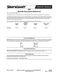
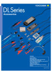
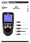
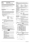
User's
Manual
Model 701944/701945
100:1 Probe
IM 701944-01E
2nd Edition
Introduction
This 701944 and 701945 probe is the high voltage probe with a 100:1
attenuation. The very sharp probe tip is spring loaded and minimizes the
pressure to the device under test. It also prevents the probe from slipping on
the board surface. In particular, the spring mechanism is useful when using
the probe with it inclined. The probe tip is changeable. Replacement tips are
provided in the accessory pack.
Checking the Contents of the Package
If some of the contents are not correct, or if any items are missing
contact the dealer from which you purchased them. 701944/701945 probe main unit
Accessories
User's Manual (this manual):
1
Pincher tip:
1
Standard ground lead:
Adjustment tool: 1
Rigid tip:
Spring tip*:
1
Color coding rings:
Insulation cap: 1
Protection cap**: *: Installed in the probe
or damaged,
1
1
1 set
1
**:Plugged on the probe
Revisions
1st Edition
2nd Edition
November 2006
March 2007
2nd Edition : March 2007 (YK)
All Rights Reserved, Copyright © 2006 Yokogawa Electric Corporation
IM701944-01E
Conventions Used in This Manual
Improper handling or use can lead to injury to the user or damage
to the instrument. This symbol appears on the instrument to
indicate that the user must refer to the user's manual for special
instructions. The same symbol appears in the corresponding
place in the user's manual to identify those instructions. In
the manual, the symbol is used in conjunction with the word
"WARNING" or "CAUTION."
WARNING
Describes precautions that should be observed to prevent serious
injury or death to the user.
CAUTION
Describes precautions that should be observed to prevent minor
or moderate injury, or damage to the instrument.
Note
Provides important information for the proper operation of the
instrument. Waste Electrical and Electronic Equipment (WEEE),
Directive 2002/96/EC
(This directive is only valid in the EU).
This product complies with the WEEE Directive (2002/96/EC) marking requirement.
The following marking indicates that you must not discard this electrical/electronic product in domestic household waste.
Product Category
With reference to the equipment types in the WEEE directive Annex 1, this product is classified as a “Monitoring and Control instrumentation” product.
Do not dispose in domestic household waste.
When disposing products in the EU, contact your local Yokogawa Europe B. V.
office.
IM701944-01E
Safety Precautions
To safely operate this product and to fully utilize its functionality, strictly observe
the following cautions.
This product complies with the requirements stated in measurement categories I
and II, and pollution degree 2 defined in IEC61010-031.
If this probe is operated in a manner not specified in this manual, this may cause
the protection capability of this product to lessen. Additionally, YOKOGAWA
shall not be held responsible for defects arising from negligence of such
warning and caution, and also shall not guarantee the product in such case. Before using this probe, thoroughly read the instruction manual for measuring
instrument to fully understand the specifications and handling precautions for
safe and correct operation.
IM701944-01E
WARNING
• Grounding of the measuring instrument
The protective grounding terminal of the measuring instrument
must be connected to ground.
• Ground lead of the probe
Make sure to connect the ground lead of the probe to the ground
(ground potential).
• Connecting the object of measurement
Make sure to avoid an electric shock when connecting the probe
to the object of measurement. Do not remove the probe from
the measuring instrument after the object of measurement is
connected.
• Do not operate with suspected failures
If you suspect that there is damage to this probe, have it inspect
by a service personnel. • Maximum input voltage
Do not apply any voltages exceeding the maximum input voltage
to the probe.
• Do not operate in wet/damp conditions
To avoid electric shock, do not operate this probe in wet or damp
conditions.
• Do not operate in explosive atmosphere
To avoid injury or fire hazard, do not operate this probe in an
explosive atmosphere.
• Avoid exposed circuitry
To avoid injury, remove jewelry such as rings, watches, and
other metallic objects. Do not touch exposed connections and
components when power is present.
Specifications
The specifications described in this section apply to the probe connected to
Yokogawa’s oscilloscope model DL series and may vary depending on the type
of oscilloscope connected. The preconditions for the following specifications
are that the instrument should be warmed up for at least 20 minutes and the
environmental conditions should not exceed the specified limits of the probe.
Electrical Specifications
Item
701944701945
Attenuation Ratio*
100:1 ± 2% (DC)
100:1 ± 2% (DC)
Voltage Coefficient
0.0005 %/V (typical value) 0.0005 %/V (typical value)
System Bandwidth**
400 MHz (-3 dB)
250 MHz (-3 dB)
Probe Rise Time
< 900 ps (10% to 90%)
< 1.4ns (10% to 90%)
Maximum Input Voltage*** 1000 Vrms
1000 Vrms
*: This specification value is obtained when the probe is connected to an oscilloscope
having an input resistance of 1 MΩ ± 1%.
**: This specification value is obtained when the probe is connected to an oscilloscope having a bandwidth of 500 MHz or greater.
When the probe is connected to an oscilloscope having a bandwidth of less than
500 MHz, depends on the bandwidth of the oscilloscope main unit.
***:See the compatible standards shown below. See also "Voltage Derating".
Electrical Characteristics
Input Resistance (system)
Input Capacitance (system)
Input Impedance (system)
Compensation Range
Input Coupling of the measuring instrument
Mechanical Characteristics
Weight (probe only)
Cable Length
50 MW ± 1%
7.5 pF (typical value)
See also "Input Impedance."
10 pF to 50 pF (typical value)
1 MW DC/AC
Approximately 55 g
Approximately 1.2 m(701944), 3 m(701945)
External Dimensions
Unit: mm
F3.5
F14.5
81
F11
F6.5
F 18.3
151
IM701944-01E
Environmental Specifications
Altitude
Temperature Range
Maximum Relative Humidity
Operating:
Storage:
Operating:
Storage:
Operating:
Up to 2000 m
Up to 15000 m
0 °C to 50 °C
- 40 °C to 71 °C
Relative humidity of 80% at a temperature
of up to 31 °C, decreasing linearly to
relative humidity of 40% at 50 °C if the
temperature is 31 °C or higher.
Standards Compliance
This product is compliance with the following categories of IEC61010-031:
Measurement Category I Measurement Category II Pollution Degree 2 1000 Vrms, 4000 V transient over-voltage
1000 Vrms CATII
Normally, only non-conductive pollution occurs. Occasionally, however, a temporary conductivity
caused by condensation must be expected.
Definitions and Examples of IEC Measurement Category
Measurement category II Definition: Measurement category II is for
(CAT II)
measurements performed on circuits
directly connected to the low voltage
installation.
Examples:Measurement on household appliances,
portable tools, and similar devices. Measurement category I Definition: M e a s u r e m e n t c a t e g o r y I i s f o r
measurements performed on circuits not
directly connected to a main supply.
Examples:Measurements in circuits not derived
from a main supply and specially
protected (internal) circuits derived from
a main supply.
IM701944-01E
Voltage Derating
CAUTION
• As the frequency of the input signal increases, the maximum
rating of the input voltage of the probe decreases. For details
about appropriate input voltage, see Section 3, Specifications.
Typical Voltage Derating
Amplitude AC rms [V]Sinus
1200
1000
800
600
400
200
0
0.1
1
10
100
1000
Frequency [MHz]
Input Impedance
CAUTION
• As the frequency of the input signal increases, the input
impedance of the probe decreases.
Typical input impedance
100000.00
10000.00
|Z| [KOhm]
1000.00
100.00
10.00
1.00
0.10
0.01
1E-05 0.0001 0.001
0.01
0.1
1
Frequency [MHz]
10
100
1000
IM701944-01E
Maximum Pulse Ratings
For pulse measurements make sure to comply with the ratings as shown below.
Maximum Pulse Derating
Measurement Category I
Maximum Peak Pulse Voltage
6000
5500
5000
Dutycycle
4500
4000
10%
3500
25%
50%
3000
2500
2000
1500
1000
10
100
1000
Duration [msec]
IM701944-01E
Handling
CAUTION
• Since the spring type contact tip is very thin and sharp, great care
should be taken to prevent personal injury when the contact tip
is mounted. In particular, handle the spring type contact tip with
great care. The probe cable is a delicate part of the probe. If the
probe cable is bent or pulled forcibly, this may cause the cable
to break. To keep the accuracy and protect the product, do not
apply any impact or shock to the product.
• Cautions When Using the Probe with DL1700 Series Instruments
Yokogawa DL1700 series digital oscilloscopes (excluding the
DL1700E) have two different types of probe connectors (A and
B in the figure below). Be sure to check which type of probe
connector your DL1700 series instrument uses. If the probe
connector is of type B, you must use an anti-interference sheet.
This sheet is provided free of charge by contacting your nearest
Yokogawa representative. If the anti-interference sheet is not
used, part of the probe can become caught on and potentially
damage the front bezel, or become unable to be disconnected. If
probe connector type A is used on your DL1700 series instrument,
the anti-interference sheet is not required.
Probe connector type
A
B
Affixing the Anti-Interference Sheet
Affix the anti-interference sheet to the DL1700 series instrument’s
probe connector as shown in the figure below.
Anti-Interference Sheet
IM701944-01E
Maintenance
Cleaning
When cleaning the exterior of the probe, clean it using a soft cloth rag moistened
with either water or isopropyl alcohol. In this case, dry the probe completely
before starting the measurement.
Changing the Probe Tip
To change the probe tip, grip the tip firmly with pliers and carefully pull it straight
out of its contact socket along the axis of the probe. Do not grip the white plastic
insulator or the housing with pliers, because this will damage the probe tip. If
the probe tip is removed, the new tip can be inserted with pliers into the socket,
along the axis of the probe. To insert the probe tip completely into the housing,
press the probe tip against a hard surface carefully.
Use pliers to grip and pull the probe tip
carefully out of its contast socket.
Do not grip the white plastic insulator
or the housing with pliers.
Adjustment Procedures
LF Compensation
LF needs to be adjusted when the probe is connected to the scope input
the first time. LF compensation matches the probes cable capacitance to
the oscilloscope input capacitance. This matching assures good amplitude
accuracy from DC to upper bandwidth limit frequencies. A poorly compensated
probe clearly influences the overall system performance (probe + scope) and
introduces measurement errors resulting in inaccurate readings and distorted
waveforms.
LF compensation is performed by connecting the probe to the COMP-output on
the oscilloscope and adjust the LF compensation trimmer (see also the Figs.
below.) optimum square wave response.
Under compensated
Optimum
Over compensated
LF Compensation
IM701944-01E
HF Compensation
HF needs to be adjusted when the probe is connected to the scope input the
first time.
HF adjustment is performed by connecting the probe to a rectangular wave
generator with first rise time. Adjust the trimmer for optimum wave response.
Optimum
DC Adjustment
In order to provide highest accuracy this probes dividing ratio is factory adjusted
using 500 VDC source and measuring device with a precision input impedance
of 1 MW ± 1%.
LF Compensation
DC
HF Compensation
Replaceable Parts
Replaceable parts are prepared as sets. When ordering any replaceable part
set, inform a desired set name and its part number.
Accessories Basic(part number: B9852HK)
Pincher tip:
2
Standard ground lead:
2
Rigid tip: 2
Spring tip: 2
Accessories HV(part number: B9852HL)
Safety Alligator Clip:
Flexible Adapter: Ground Lead 22 cm to 4 mm banana plug:
10
2
1
1
IM701944-01E
List of Accessories
CAUTION
• Use ground lead only for grounding connections.
• Do not use any accessories other than those originally provided.
Adjustment Tool
Set Coding Rings
3x4 colors
Solid Tip
(&:0.8mm)
Spring Tip
(&:0.8mm)
Ground Lead (L:22cm,)
Insulating Cap
Protection Cap
Pincher Tip
Flexible Adapter 5.0-L to
4 mm
IM701944-01E
Ground Lead 22 cm to 4 mm
banana plug
Safety Alligator Clip
11
YOKOGAWA ELECTRIC CORPORATION, Communication & Measurement Business Headquarters
Phone: (81)-422-52-6768, Fax: (81)-422-52-6624, E-mail: [email protected]
YOKOGAWA CORPORATION OF AMERICA
YOKOGAWA EUROPE B.V.
Phone: (1)-301-916-0409, Fax: (1)-301-916-1498
Phone: (31)-33-4641858, Fax: (31)-33-4641859
YOKOGAWA ENGINEERING ASIA PTE. LTD.
Phone: (65)-62419933, Fax: (65)-62412606