1
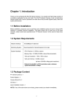
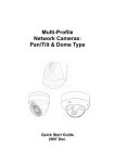
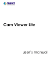
20 Meter IR Vandal Proof Dome
Internet Camera
ICA-525
Quick Installation Guide
Table of Contents
Before Installation............................................................................................. 3
System Requirements ...................................................................................... 3
Package Content............................................................................................... 4
Identification of Cables...................................................................................... 5
Inside the TEL box:.......................................................................................... 6
Hardware Installation........................................................................................ 7
Initial Utility Installation and operation..............................................................10
Wizard function:..............................................................................................13
Username and Password: ................................................................................14
Configure Utility Installation..............................................................................15
Appendix A: Feature Listing for Cam Viewer .....................................................19
Appendix B: Suggest Hardware / System Requirement.......................................20
Ordering Information for Cam Viewer Pro..........................................................20
Further Configuration.......................................................................................20
Thank you for purchasing the ICA-525. It is versatile and high image solution
of surveillance application for day and night. The ICA-525 is also a stand-alone
camera system with a built-in processor and web server that provides highest
quality video and system performance.
Before Installation
Before installation, please be sure to read this quick installation guide or user’s
manual of bundle CD carefully to complete machine installation.
System Requirements
Network
Interface
10/100M Base-TX Ethernet
Monitoring
System
Recommended for Internet Explorer 6.0 or later
System
Hardware
●
●
●
●
●
CPU: Pentium 4, 1.5GHz or above
Memory Size : 512 MB (512 MB or above Recommended)
VGA card resolution : 1024 x 768 or above
Sound Card : Necessary
Network bandwidth: In VGA resolution mode, minimum upload bandwidth is 1Mbps
Package Content
ICA-525 x 1
Power Adapter x 1
Screws x 4
Telephone box x 1
L-Wrench x 1
CD Disk x 1
Quick Installation Guide x 1
Note
1. If any of the above items are missing, please contact your dealer
immediately.
2. Using a power supply with a different voltage that the one
included with the ICA-525 will cause damage and void the
warranty for ICA-525.
Identification of Cables
RJ-45 LAN
Video out
RS-485 & DI/DO
(Connect to a bundled TEL box)
Line in
12V DC in
Line out
1.RJ45 LAN socket: Connect to PC or Hub/Switch. For connect to 10Base-T
Ethernet or 100Base-TX Fast Ethernet cabling. This Ethernet port built N-Way
protocol can detect or negotiate the transmission speed of the network automatically. Please use Category 5 “straight through” cable to connect the ICA-525
to a 100Mbps Fast Ethernet network switch or hub.
Note
In case you need to connect the device to PC or notebook directly,
you should use cross over cable instead.
2.RS-485 & DI/DO: Connect to a local keyboard controller and connect to sensor
in and alarm out devices.
Inside the TEL box:
Name
Function
12VDC
DC 12V output (50mA maximum)
GND
GND
D+
RS485 data +
D-
RS485 data -
DI
Digital signal input
DO
Digital signal output
The RS-485 of ICA-525 is master that can control external scanner.
Note
3.Local Video output (BNC port): The Network Camera also provides composite
video output. User can use BNC video cable to connect the Network Camera with
a TV monitor or VCR.
4.DC-in Jack: The input power is 12VDC. Note that supply the power to the
Network Camera with standard power adapter included in package. Otherwise,
the improper power adapter may damage the unit and result in danger.
5.Line in (audio in): Connect an audio input source to the ICA-525.
6.Line out (audio out): Connect a loud speaker to the ICA-525. This function is
for voice alerting and two-way audio.
Hardware Installation
1.Use the provided L-wrench, loosen the tamper-resistant housing cover (with
screws still attached on the cover). The unit has factory installed side conduit
entry and one may adjust the cables to back conduit entry according to installation requirement.
Note
During the installation, please take care and avoid crash. That may
cause the device damage.
2.Set the mounting base onto the wall or ceiling and center it over the mounting
hole, using the supplied four retaining screws to secure the main body.
3.Set the proper image by moving the camera body and set the focus by turning
the lens to left or right direction.
Note
1. Vari-Focal Dome Operation Guide: Once the picture appears
on the monitor, open the cover and adjust the lens wrench to
“NEAR f g FAR”, get the view zoom that you desire, and then
adjust the focus wrench of the lens to obtain the best picture.
After adjustment, tighten both wrenches.
2. During adjust focus, please take cares that don’t touch, collision
and knock sensor.
Zoom Adjustment
NEAR
TELE
Focal Adjustment
FAR
WIDE
4.When the ICA-525 focus adjustment has been completed, use the provided Lwrench to fasten the tamper-resistant housing to the main body.
5.When using the side conduit cabling, it is suggested to cover the cables using
metal covers (to prevent external damage and for waterproof prevention), and
wined the waterproof adhesive type onto the metal cover before installation.
6.Connect the LAN cable to Ethernet’s switch or hub and the DC-Jack to the power
source. The video output to monitor or other video through a 75 Ohms type
coaxial cable if you will use BNC cable.
7.Done
Initial Utility Installation and operation
1.Insert the bundled CD into the CD-ROM drive to launch the autorun program.
Once completed, a welcome menu screen will appear.
2.Click the “IPWizard” hyperlink, you will see the InstallShield Wizard dialog box as
below.
Note
If the welcome screen does not appear, click “Start” at the taskbar.
Then, select “Run” and type “D:\Utility\setup.exe”, assume D is
your CD-ROM drive.
3.The “Welcome to the InstallShield Wizard for IPWizard” will display on the screen
and click “Next” to continue.
10
4.Please click “Next” to install with original settings, or you may click “Change…”
button to modify the install folder then press “Next” to continue.
5.Please click “Install” to start the installation.
11
6.Please click “Finish” to complete the installation
7.Please double-click the utility icon
ICA-525 utility.
on the desktop then you will see the
8.Press “Search” button. IP Wizard will list all IP Cameras in your LAN environment:
12
Wizard function:
Note
Please select your ICA-525 and press “Wizard”. The utility featured
of “Wizard” function to help user to initial ICA-525. User can setup
IP address, username and password step by step.
Please enter User Name and Password. Default Username is: admin, leave
password blank. Then click “Submit”.
13
Username and Password:
You may change the ID and assign a new password to your ICA-525 or keep the
original and press “Next” to continue.
As below, you can select “Static IP” and enter the IP settings. Or select “DHCP ON”
when there is a DHCP server in your network.
If no IP address is assigned after 30 seconds, ICA-525 will use its default address
192.168.0.20. User may open your web browser, and key in http://192.168.0.20 in
the address field to login web configuration page and refer to our User’s manual in
the bundled CD disk to configure.
14
Configure Utility Installation
Note
The Cam Viewer Lite/Pro 30 days trial version installation steps are
similar. Below is the installation of Cam Viewer Lite.
1.Insert the bundled Cam Viewer CD disk into the CD-ROM drive to launch the
autorun program. Once completed, a welcome menu screen will appear. Click
the “Cam Viewer Lite” hyperlink, the below InstallShield Wizard dialog box will
appear.
Note
If the welcome screen does not appear, click “Start” at the taskbar.
Then, select “Run” and type “D:\Cam Viewer Lite\setup.exe”,
assume “D” is your CD-ROM drive.
2.Selects the language which you want, Cam Viewer is current including fifteen
languages. Please select one of the language and click ”Next” to continue.
15
3.The “Welcome to the InstallShield Wizard for Planet Cam Viewer Lite 1.0.0” will
display on the screen, please click “Next”.
4.Please read the license agreement and then check “I accept the terms of the
license agreement” if you are agreed and click “Next” to continue the installation
16
5.Please key in user name and company name for which you want and click “Next”
to continue installation.
6.Check the option “Complete” – all program features will be installed (Requires
the most disk space) and click “Next” to continue installation.
17
7.“Ready to Install the Program” will appear to prompt you to start the installation.
Please click “Install” to start.
8.Please click “No” to finish the Cam Viewer Lite installation.
Note
In above step, when Cam Viewer works with MBM5 (Motherboard
Monitor 5), Cam Viewer will display CPU temperature and fan
speed. Please click “Yes” if you need this function and refer to the
manual of Cam Viewer CD disk for complete installation.
For more information, please refer to the User’s manual in the bundled CD.
18
Appendix A: Feature Listing for Cam Viewer
Software Version
Cam Viewer Lite
Cam Viewer Pro
IP Camera Input
32
16 / 32 / 64
Dual Monitor
-
V
Smart Guard
-
V
I/O Device
V
Hotline
-
V
Address Book
-
V
Log Viewer
Unusual event
System log
Unusual event
System log
Counting application
Counting Application
-
2 way counting
Remote Playback Server
-
Unlimited
Concurrent Playback
1 Channel
16 Channels
Counting Function
-
V
General Motion
General Motion
Missing Object
Foreign Object
Lose Focus
Camera Occlusion
1 Channel
16 Channel
Smart Search
Remote Live Viewer
19
Appendix B: Suggest Hardware / System Requirement
Total FPS
~600
600~480
480~240
240~120
120~
CPU
Intel Core
2 Duo
QX6800
Intel Core
2 Duo
E6600
Intel
Pentium D
930
Intel P4
3.0 GHz
Intel P4
2.8 GHz
RAM
4 GB
2 GB
2 GB
1 GB
1 GB
Chipset of
Motherboard
Intel 946 or 965 chip, Intel Chipset recommended
VGA Card
ATI Radeon 9200, nVIDIA GeForce FX-5200,
Intel 945/965 or above (ATI recommended)
Ethernet
100 Base-TX or Above, Gigabit LAN recommended
Hard Disk
160 GB or above
O.S.
Windows 2000 / XP / 2003
Total FPS: Means all the cameras will spend how many frames when this software
works. Suppose there are 10 cameras, each one will work with 30fps, the total fps
should be 300fps.
Ordering Information for Cam Viewer Pro
Model
Description
CVP-16
16-Channel Cam Viewer Professional
CVP-32
32-Channel Cam Viewer Professional
CVP-64
64-Channel Cam Viewer Professional
Further Configuration
If you want to configure more detail settings of ICA-525, please refer to the user
manual in the CD disk.
20