1
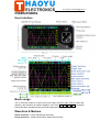
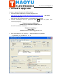
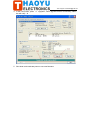
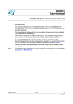
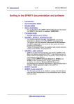
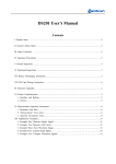
Tech Support: [email protected]
DSO Nano Manual
v1.0b
Intro
DSO mobile is a pocket size digital storage oscilloscope fulfills basic electronic engineering
requirements. It is base on ARM Cortex™-M3 compatible 32 bit platform, equipped with
320*240 color display, SD card capability, USB connection, and chargeable batteries.
Features
Super portable and lightweight
2.8” color 320*240 display
Micro SD card Waveform Storage
Basic 1Msps sample rate with 12bit resolution
Various measurement markers
Various trigger mode
Build-in test signal
USB chargeable battery
Open source
Tech Support: [email protected]
Specification
Display
2.8" Color TFT LCD
Display Resolution
320×240
Display Color
65K
Analog bandwidth
0 - 1MHz
Max sample rate
1Msps
Sample memory depth
4096 Point
Horizontal sensitivity
1uS/Div
Horizontal position
adjustable with indicator
Vertical sensitivity
10mV/Div
12Bits
~10S/Div (1-2-5 Step)
~10V/Div (with ×1
probe)
~10V/Div (with ×10
probe)
0.5V/Div
Vertical position
adjustable with indicator
Input impedance
>500KΩ
Max input voltage
80Vpp (by ×1 probe)
Coupling
DC
Trig modes
Auto, Norma, Single, None and Scan
Functionalities:
Automatic measurement: frequency, cycle, duty, Vpp,
Vram, Vavg and DC voltage
Precise vertical measurement with markers
Precise horizontal measurement with markers
Rising/falling edge trigger
Trig level adjustable with indicator
Trig sensitivity adjustable with indicator
Hold/run feature
~
Test signal
Built-in 10Hz 1MHz (1-2-5 Step)
Waveform storage
SD card
PC connection via USB
as SD card reader
Upgrade
by bootloader via USB
Power supply
3.7V Chargeable Lithium battery / USB
Dimension (w/o probe)
105mm X 53mm X 8mm
Tech Support: [email protected]
Instructions
User interface
Basic usage
The UI could be divided to 4 parts: main menu (top), functions (right column), status bar
(bottom), and waveform & markers displays. Use cursor ▲ , ▼ , ◄ , ► to navigate
among the three operational parts and make adjustments.
Waveform & Markers
Green waveform - current signal being monitored
Purple waveform – reference waveform loaded from SD card.
Tech Support: [email protected]
Voltage measure marker V1 and V2 (Dot, vertical) – A voltage measure value between
V1-V2 could be displayed.
Time measure marker A and B (Dot line, horizontal) – A time measure value between A
and B could be displayed.
Y positions marker (Purple) – Y position center line for adjustment reference
Trigger level marker (Yellow) – Used to set trigger level
Menu
Horizontal main menu on top of screen, Navigate by
◄,►
, adjust by ▲ , ▼
Sync. Mode:
When blinking, press ▲ and ▼ to select 4 different synchronization
mode: AUTO, NORM, SING, and NONE.
AUTO – Automatic synchronous sweeping mode, displays waveform even not
triggered.
NORM – Normal synchronous sweeping mode, displays whenever trigged.
SING- Single sweeping mode, display when triggered, then stopped with latest
triggered waveform.
NONE – Random sampling mode
SCAN – Scan mode, to check long period low frequency signal.
Vertical Scale: When blinking, press ▲ and ▼ to select different level of sensitivity.
Total 19 scales are optional from 10mV/Div to 100V/Div. Note 1: If you use scale above
20V/Div, please use probe with attenuation of 10:1). Note 2: If newly set scale does not
match reference waveform, the latter will be cleared.
Horizontal sensitivity: When blinking, press ▲ and ▼ to select different sensitivities. ,
from 1uS/Div to 10S/Div total 22 grades. Note 2: If newly set sensitivity does not match
reference waveform, the latter will be cleared.
Y position: When blinking, press ▲ and ▼ to adjust the vertical position of the
waveform. Press M to hide/activate Y position marker if needed.
Calculation Mode: Auto calculation modes include:
FREQN – Signal frequency
CYCLE – Signal period
DUTY – Duty time
Vpp – AC signal peak-peak value
Vram – AC signal effective value
Vavg – AC signal average value
DC.V – DC signal average value.
Power supply mode: Power supply by internal battery or USB port. Battery bar will be
displayed when powered from internal.
Functions
Vertical function buttons on side of screen, Navigate by ▲ , ▼ adjust by ◄ , ►
Trigger sensitivity: When blinking, press ◄ and ► to adjust trigger sensitivity,
trigger level marker (Yellow dotted area) changes correspondingly.
Tech Support: [email protected]
Trigger Type: When blinking, press ◄ and ► to choose trigger mode of rising edge
or falling edge.
Probe attenuation scale: When blinking, press ◄ and ► to choose 1:1 or 1:10
probe.
Save waveform: When blinking, status bar will display “ Save Filexxx”, press ◄ and
► to select file name with xxx = 000-255. Press M to save current waveform on
display to SD card.
Load waveform: When blinking, status bar will display “ Save Filexxx”, press ◄ and
► to select file name with xxx = 000-255. Press M to load current waveform to
display from SD card.
Note: current version has no file creation function, a FILEXXX.DAT must be prepared
by connecting to PC by USB.
Ref. square wave freq.: When blinking, press ◄ and ► to adjust the frequency of
reference square wave.
:
Horizontal position adj. When blinking, press
◄
and
►
to scroll waveform
horizontally.
Index Bar: Show current display position of total loaded wavefrom
Status Bar
Time markers.: When blinking, press ◄ and ► to adjust T1 or T2 time measure
marker, the time difference ∆T=T1-T2 will be displayed.
Voltage markers: When blinking, press ◄ and ► to adjust V1 or V2 time measure
marker, the Voltage difference ∆V=V1-V2 will be displayed.
Trigger level: When blinking, press ◄ and ► to adjust trigger level, trigger level
marker (Yellow dotted line) changes correspondingly.
Save Settings
Hold “R/S” Button and press “M” button to save current settings as default.
Tech Support: [email protected]
Firmware upgrade
It’s easy to upgrade firmware with USB bootloader.
1. Download “DfuSe USB Device Firmware Upgrade” from
http://www.st.com/stonline/products/support/micro/files/um0412.zip and install.
Instruction available at
http://www.st.com/mcu/familiesdocs-110.html#Application%20Note.
2. Connect Oscilloscope with PC, press and hold – , switch on power, until
oscilloscope displays:
"Please Connect to USB Host!"
"DS0201 Device Firmware Upgrade Ver 1.0"
When PC connection is detected,
"Firmware Upgrading..."
"Please Wait"
"DS0201 Device Firmware Upgrade Ver 1.0"
)
) ()
3. Run “Dfuse Demo” on PC, check (1 , select firmware to be uploaded
e,g."DS0201_FW_V2.00.DFU" at 2
(
Tech Support: [email protected]
( )"Upgrade", when upgrade finishes successfully, status
4. In the next screen, press 1
bar will notify 2
()
5. Shut down and reactivate power to use new firmware.
Page 8 of 9
10/26/2009