1
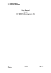
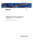
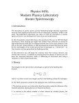
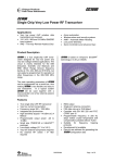
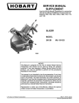
User Manual Rev. 1.22 SmartRF ® CC1000PP Plug and Play Module Chipcon AS, Gaustadalléen 21, N-0349 Oslo, Norway. Support tel: +47 22 95 85 45, fax: +47 22 95 85 46. E-mail: [email protected] Table of contents TABLE OF CONTENTS .......................................................................................................... 2 INTRODUCTION ..................................................................................................................... 3 TYPICAL PERFORMANCE..................................................................................................... 3 MECHANICAL DIMENSIONS AND COMPONENT PLACEMENT......................................... 4 CIRCUIT DIAGRAM ................................................................................................................ 4 LAYOUT .................................................................................................................................. 8 ANTENNAS ............................................................................................................................. 8 BILL OF MATERIALS ............................................................................................................. 8 BILL OF MATERIALS, CC1000PP-433...................................................................................... 9 BILL OF MATERIALS, CC1000PP-868.................................................................................... 10 Chipcon AS SmartRF CC1000PP Plug and Play Module User Manual (rev. 1.22) 2003-02-03 Page 2 of 11 Introduction The CC1000 is a very flexible and feature-rich single-chip very low-power RF transceiver. Chipcon has designed the CC1000PP plug-and-play module to serve as a reference layout and enable very quick prototyping of an RF system. The tiny CC1000PP module (28x20 mm) contains all RF components required for proper operation. This includes all the components mentioned in the CC1000 application circuit (see datasheet for details), as well as a reference crystal and a LC output filter. The layout is based on a standard, inexpensive 2-layer 1.6mm thick FR-4 PCB process, and has been carefully optimised by Chipcon. Components are mounted on one side only, the component side is used for signal routing, and the “solder” (reverse) side is used for a ground plane. The CC1000PP layout can easily be used as a reference layout by importing it into a PCB CAD program. Chipcon provides the layout in the industry-standard Gerber format. To download the files, please visit the Chipcon web site. As the CC1000PP module contains only the components required for operation, the layout does not require major modifications when used to make a custom PCB, the user can merely delete the connector pins at each end of the module. But it is very important that the component placement, routing and vias are not altered if the same performance is to be achieved. If a four layer PCB is to be used, either the two top layers should be used for the RF part, or layer 1 and 4. Layer 4 should then be the ground plane and layers 2 and 3 should be masked off. In a ready-built form, the CC1000PP is ideal for quick prototyping. The module may be connected to a prototyping board or PCB containing the rest of the system. The CC1000 can in this way be tested in a complete system without having to create a custom RF PCB layout. Full documentation is provided for this module, including schematics and PCB layout. This information can be downloaded from Chipcon’s web site. Typical performance The table below shows typical performance at 3 V / 25°C. Parameter CC1000PP-433 CC1000PP-868 Unit 433 MHz 868 MHz 915 MHz Sensitivity, 2.4 kBaud -111 -107 -105 dBm Output power, max 8 2.5 0.5 dBm RF frequency accuracy ± 10 ± 10 ± 10 ppm LO leakage -68 -62 -59 dBm nd <-36 <-30 <-40 dBc dBm rd 3 harmonic <-30 <-30 <-40 dBc dBm Current consumption, TX 24 23 23 mA Current consumption, RX 9.7 11.7 11.7 mA Current consumption, PD 100 100 100 nA 2 harmonic Chipcon AS SmartRF CC1000PP Plug and Play Module User Manual (rev. 1.22) 2003-02-03 Page 3 of 11 Mechanical dimensions and component placement The CC1000PP module measures 28x20mm, and has been designed for a two-sided 1.6mm thick PCB using industry-standard FR-4 board material. Components are mounted on only one side, and the result is a very small, inexpensive module that can satisfy regulation requirements. On each end of the board are connectors for interfacing the module to an external system. An external antenna, and a 2.1-3.6V power supply should be connected to the top connector (P2). The RSSI/IF signal can also be accessed via this connector. The lower connector (P1) can be used to connect an external micro-controller to the data- and configuration interface of the CC1000. Figure 1. Mechanical drawing of CC1000PP module (not to scale) To ensure optimum RF performance, an external antenna should be soldered directly to the antenna terminals, or a 50 Ohm microstrip line should be used from the antenna terminal to the external antenna connector. For applications not demanding optimum RF performance, a pin-row connector may be used to connect the antenna signal to another PCB, but be aware that this can lead to non-optimal sensitivity and output power, and that measurements using this arrangement should not be used to characterise the RF performance of CC1000. For more information on antennas, please see Chipcon application note AN003. Circuit diagram The circuit diagram of the CC1000PP is shown below. There are two versions of the CC1000PP module, the CC1000PP-433 for 433 MHz operation, and the CC1000PP-868 for operation in the 868 MHz and 902-928 MHz bands. Since the 868 version covers both the European 868 MHz band and the US 902-928 MHz band, one system can be used in both Europe and the US using the same hardware, changing the frequency by software control. The circuit is similar to the application circuit shown in the CC1000 data sheet, with an added LC filter to reduce emitted harmonics. Chipcon AS SmartRF CC1000PP Plug and Play Module User Manual (rev. 1.22) 2003-02-03 Page 4 of 11 The value of the matching components, the VCO inductor and the LC filter will depend on the operating frequency. Bills of materials are supplied for both versions. For operating ® frequencies other than those listed here, please use the latest version of SmartRF Studio to calculate the component values. Pinouts for the connectors are given in the table below. The position of pin number 1 is indicated on the top silkscreen of the PCB. An abbreviated description of the pin functions of P1 is also printed on the silkscreen. P1 P2 Pin Function Pin Function 1 PALE 1 GND 2 PDATA 2 ANTENNA 3 PCLK 3 GND 4 DCLK 4 VDD (2.1 – 3.6 V) 5 DIO 5 RSSI / IF 6 CHP_OUT / LOCK 6 GND Table 1. Connector pinouts Chipcon AS SmartRF CC1000PP Plug and Play Module User Manual (rev. 1.22) 2003-02-03 Page 5 of 11 Figure 2. Schematic for 433 MHz version Chipcon AS SmartRF CC1000PP Plug and Play Module User Manual (rev. 1.22) 2003-02-03 Page 6 of 11 Figure 3. Schematic for 868/915 MHz version Chipcon AS SmartRF CC1000PP Plug and Play Module User Manual (rev. 1.22) 2003-02-03 Page 7 of 11 Layout RF circuits working at high frequencies are very sensitive to the physical layout of the PCB. Chipcon has carefully optimised the layout of the CC1000PP in order to provide good RF performance. Chipcon strongly recommends that you use this layout as it is, and that you do not attempt to modify it. LO leakage is a critical parameter. To meet the ETSI requirement of –57 dBm, coupling from the VCO to the antenna or the matching network must be carefully controlled. The VCO inductor must be of the specified type and be mounted with the correct alignment if LO leakage is to meet specifications. The L101 VCO inductor should be oriented with the thick white stripe facing the crystal. To prevent coupling via the power supply, the specified decoupling capacitors must be mounted as shown. Figure 4. Top and bottom PCB layout, top silkscreen Antennas The CC1000PP can be used together with any type of single-sided antenna. Loop antennas can also be used by grounding one side. If the antenna’s impedance is not close to 50 ohms, matching components should be used to match it to 50 ohms. A quarter-wave wire antenna can be used directly by removing pins 1, 2 and 3 from P2 and soldering in a piece of wire of the correct length (one quarter wavelength). Frequency ¼ wavelength 433 MHz 16.4 cm 868 MHz 8.2 cm 915 MHz 7.8 cm Table 2: 1/4 wavelength for common frequencies For more information about antennas, please see application note AN003. Bill of materials The CC1000 is designed to be used together with low cost passive components. The components specified for the CC1000PP are the same as those listed in the data sheet. The only critical component is the VCO inductor, which must be the exact type listed in order for LO leakage to meet specifications. All other capacitors and inductors are non-critical, and any manufacturer or type may be used as long as they match the specifications in the component list. The boards manufactured by Chipcon uses Coilcraft HQ-series inductors, some of the inductor values may not be available from all manufacturers. Substituting nearby values may be possible. Chipcon AS SmartRF CC1000PP Plug and Play Module User Manual (rev. 1.22) 2003-02-03 Page 8 of 11 Bill of materials, CC1000PP-433 CC1000PP-433 Reference Description Value / tolerance Part C1 Capacitor, tantal 3.3µF C_3U3_TAN_B C6 Capacitor 0603 33nF, 10% C_33N_0603_X7R_K_25 C10 Capacitor 0603 12pF, 5% C_12P_0603_NP0_J_50 C11 Capacitor 0603 220pF, 5% C_220P_0603_NP0_J_50 C12 Capacitor 0603 1nF, 10% C_1N0_0603_X7R_K_50 C13 Capacitor 0603, general C14 Capacitor 0603 68pF, 5% C_68P_0603_NP0_J_50 C31 Capacitor 0603 15pF, 5% C_15P_0603_NP0_J_50 C41 Capacitor 0603 8.2pF, ±0.25pF C_8P2_0603_NP0_C_50 C42 Capacitor 0603 5.6pF, ±0.25pF C_5P2_0603_NP0_C_50 C71 Capacitor 0603 22pF, 5% C_22P_0603_NP0_J_50 C72 Capacitor 0603 15pF, 5% C_15P_0603_NP0_J_50 C171 Capacitor 0603 18pF, 5% C_18P_0603_NP0_J_50 C181 Capacitor 0603 22pF, 5% C_22P_0603_NP0_J_50 C210 Capacitor 0603 1.0nF, 10% C_1N0_0603_X7R_K_50 C281 Capacitor 0603 1.0nF, 10% C_1N0_0603_X7R_K_50 L32 Inductor 0805 68nH, 5% L_68N_0805_J L41 Inductor 0805 6.2nH, 5% L_6N2_0805_J L71 Inductor 0805 10nH, 5% L_10N_0805_J L101 Inductor 0805 33nH, 5% L_33N_0805_J KOA KL732ATE33NJ L210 EMI filter bead BLM18HG102SN1D, Murata P1 Pin-row connector CON6_MALE P2 Pin-row connector CON6_MALE R131 Resistor 0603 82kΩ, 1% R_82K_0603_F R281 Resistor 0603 27kΩ, 2% R_27K_0603_G U1 Single chip transceiver CC1000 X1 Crystal, HC49-SMD X14.7456MHz 10/10/10/16, (16pF load) Chipcon AS No Not Mount SmartRF CC1000PP Plug and Play Module User Manual (rev. 1.22) 2003-02-03 Page 9 of 11 Bill of materials, CC1000PP-868 CC1000PP-868 Reference Description Value Part C1 Capacitor, tantal 3.3µF C_3U3_TAN_B C6 Capacitor 0603 33nF, 10% C_33N_0603_X7R_K_25 C10 Capacitor 0603 12pF, 5% C_12P_0603_NP0_J_50 C11 Capacitor 0603 C12 Capacitor 0603 1nF, 10% C_1N0_0603_X7R_K_50 C13 Capacitor 0603 330pF, 5% C_330P_0603_NP0_J_50 C14 Capacitor 0603 8.2pF, ±0.25pF C_8P2_0603_NP0_C_50 C31 Capacitor 0603 10pF, 5% C_10P_0603_NP0_J_50 C41 Capacitor 0603 C42 Capacitor 0603 4.7pF, ±0.25pF C_4P7_0603_NP0_C_50 C71 Capacitor 0603 8.2pF, ±0.25pF C_8P2_0603_NP0_C_50 C72 Capacitor 0603 6.8pF, ±0.25pF C_6P8_0603_NP0_C_50 C171 Capacitor 0603 18pF, 5% C_18P_0603_NP0_J_50 C181 Capacitor 0603 22pF, 5% C_22P_0603_NP0_J_50 C210 Capacitor 0603 C281 Capacitor 0603 1nF, 10% C_1N0_0603_X7R_K_50 L32 Inductor 0805 120nF, 5% L_120N_0805_J L41 Inductor 0805 2.5nH, 5% L_2N5_0805_J L71 Inductor 0805 5.6nH, 5% L_5N6_0805_J L101 Inductor 0805 4.7nH, 5% L_4N7_0805_J, KOA KL732ATE4N7C L210 EMI filter bead BLM18HG102SN1D, Murata P1 Pin-row connector CON6_MALE P2 Pin-row connector CON6_MALE R131 Resistor 0603 82kΩ, 1% R_82K_0603_F R281 Resistor 0603 27kΩ, 2% R_27K_0603_G U1 Single chip transceiver CC1000 X1 Crystal, HC49-SMD X14.7456MHz 10/10/10/16, (16pF load) Chipcon AS Do not mount Do not mount Do not mount SmartRF CC1000PP Plug and Play Module User Manual (rev. 1.22) 2003-02-03 Page 10 of 11 Disclaimer Chipcon AS believes the furnished information is correct and accurate at the time of this printing. However, Chipcon AS reserves the right to make changes to this product without notice. Chipcon AS does not assume any responsibility for the use of the described information. Please refer to Chipcon’s web site for the latest update. General Information Chipcon AS believes the furnished information is correct and accurate at the time of this printing. However, Chipcon AS reserves the right to make changes to this product without notice. Chipcon AS does not assume any responsibility for the use of the described product. Please refer to Chipcon’s web site for the latest update. SmartRF is a registered trademark of Chipcon AS. SmartRF is Chipcon's RF technology platform with RF library cells, modules and design expertise. Based on SmartRF Chipcon develops standard component RF-circuits as well as full custom ASICs based on customers' requirements. Chipcon AS SmartRF CC1000PP Plug and Play Module User Manual (rev. 1.22) 2003-02-03 Page 11 of 11