1
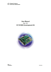
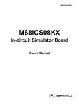
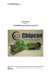
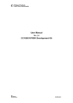
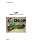
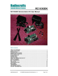
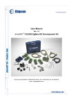
User Manual
Rev. 2.0
CC1050DK Development Kit
SWRU053
Page 1 of 20
Table of contents
INTRODUCTION ....................................................................................................................... 3
EVALUATION BOARD ............................................................................................................. 4
DESCRIPTION ........................................................................................................................... 4
LAYOUT SKETCHES ................................................................................................................... 7
ASSEMBLY DRAWING ................................................................................................................ 9
CIRCUIT DIAGRAM ................................................................................................................... 10
BILL OF MATERIALS ............................................................................................................... 114
USING THE DEVELOPMENT KIT.......................................................................................... 17
SWRU053
Page 2 of 20
Introduction
The CC1050 single chip transmitter includes many features and great flexibility, which makes
the chip suitable for a very large number of applications and system requirements. The
CC1050DK Development Kit is designed to make it very easy for the user to evaluate
transmitter performance and in short time develop his own applications.
The Development Kit includes one evaluation board with a complete CC1050 transmitter,
voltage regulator and PC interface circuitry. Using the evaluation board connected to a PC
running the SmartRF® Studio software, various system parameters can be changed and
tested by keystrokes.
Technical features:
- RF power up to 12/8 dBm (433/868 MHz) programmable in 1 dB steps
- Logic level data input (Manchester coded or NRZ)
- Logic level synchronisation clock output
- All set-up controlled by PC
- Selectable 3 V or 4-10 Vunregulated voltage supply inputs
This user manual describes how to get started with the Development Kit. You will also find
detailed description of the evaluation board and advice how to develop your own applications.
For details on how to use the SmartRF® Studio software please refer to the SmartRF® Studio
User Manual.
Your SmartRF® CC1050DK Development Kit should contain the following items:
Kit contents
Item
Number of articles
Evaluation Board (CC5000EB)
1
PC parallel port extension cable (25-pin D-sub, male-female, 3m)
1
Adapter (SMA male-BNC female)
3
Antenna (50Ω, λ/4 monopole, SMA male)
1
Quick Start User Manual
1
CC1050 sample kit
1
The evaluation board includes a significant number of components for great flexibility.
However, only a minor part of these components are required in an actual application. Check
the datasheet for a typical application circuit.
SWRU053
Page 3 of 20
Evaluation Board
The kit includes an Evaluation Board (CC1050EB) with the following items:
•
A SmartRF® CC1050 chip.
•
Necessary external surface mounted devices, SMDs, for the chip.
•
Voltage regulator 4 –10 V to 3V regulated voltage.
•
Possibilities to apply a 3 V voltage source directly (chosen by the switch on the board).
•
Voltage-level interface circuits between the CC1050 chip (3 V) and the parallel port of
the computer (5 V).
•
Connector for a PC parallel port cable.
•
Connector for antenna, modulation data in and synchronisation clock out.
•
Pin connector for interfacing to MCU
This board is designed for great flexibility so that you can evaluate the circuit performance for
several circuit configurations, and in development of your own applications. The evaluation
board is distributed in two versions, and the difference is the frequency band of operation.
The two versions are optimised for 433 MHz and 868 MHz to cover the two licence free band
in Europe. The operating frequency band is marked on the Evaluation Board.
Description
The evaluation circuit board constitutes of three main parts. These are the RF-section, the
voltage supply and the PC-interface. The PC-interface contains voltage level shift circuit,
which buffers the control lines.
Voltage supply
You can chose between applying a 4-10 V non-regulated supply voltage or a 3 V regulated
supply voltage by setting a switch on the board (SPDT). If a non-regulated supply voltage is
applied, an on board regulator generates a regulated 3 V supply. A diode prevents damage if
wrong polarity is used for the non-regulated input. The connector has five contacts, which is
shown below. In addition to the three supply voltage contacts, there are two contacts, which
can be used to measure the DC current to the CC1050 chip. A short jumper is placed
between these two contacts for the circuit to work. If you want to measure the DC current,
replace the jumper with an amperemeter (as shown in the figure below). The current range is
from 0 to 26 mA.
SWRU053
Page 4 of 20
4-10V
0V
3V
A
Iout
Iin
Figure 1: The power connector with an amperemeter attached.
RF-section
The RF section consists of a CC1050 chip with external components. The different
components are explained below.
The loop filter
The CC1050 has integrated the loop-filter and shaping features on-chip. For flexibility it is
also possible to use an external loop-filter. The PLL loop filter contains the components C5C6 and R2. However, in most cases the internal filter will give the optimum performance. The
loop filter is connected to the same pin as the monitoring of the lock indicator. When external
loop-filter is added, the R80 must be removed to avoid conflict with the lock line connected to
the parallel port.
The LOCK signal
A LOCK signal is connected to the parallel port interface to be monitored by the software. The
signal tells you if the synthesiser frequency is in lock. It is also available at P4, and is active
high.
This digital output can also be configured to other functions, as control signal for external PA.
Please see the data sheet for details.
Note: To monitor this signal CC1050 must be configured to take out this signal on CHP_OUT.
This is the default setting of SmartRF Studio. If external loop filter is added the lock signal
cannot be used due to the loop filter is connected to the same pin.
DI and DCLK
The modulation input (DI) and the synchronisation output (DCLK) is connected to separate
connectors. The connectors are of SMA female type. The data to be sent can be of either
Manchester or NRZ. The Manchester code ensures that the signal has no DC component.
The Manchester code is based on transitions; a “0” is encoded as a low-to-high transition, a
“1” is encoded as a high-to-low transition. See figure below. Maximum data-rate is 38.4 kbit/s
SWRU053
Page 5 of 20
giving a baud rate of 76.8 kbaud that is chosen in the software. For NRZ the baud rate is
equal to the bit rate and is maximum 76.8 kbit/s.
Please have in mind that the DI line must be of NRZ format even for Manchester mode
selection. The encoding to Manchester is in this mode done internally by CC1050.
The CC1050 has an internal clock synchronisation circuit that can be monitored on DCLK.
The relationship between DI and DCLK is given in the CC1050 data sheet.
PA matching
The output-matching network is optimised for either 433 MHz or 868 MHz operation. The
component values are calculated in the software program, and consist of L2, C1 and C2.
Using the specified component values for the output match will give an optimum match at the
specified operating frequency. Minor tuning of the component values may be necessary to
compensate for layout parasitics at other frequencies or other layouts. A T-type LC-filter is
used for reducing the harmonics. See Application note AN028 Improved LC-filter for details.
The crystal oscillator
The crystal frequency, X1, is set to 14.7456 MHz. The crystal oscillator circuit has a trimmer
capacitor, CT52, which reduces the initial tolerance of the crystal to zero by careful
adjustment using a precision frequency counter. The crystal used at this board has ±10 ppm
accuracy and ±10 ppm over the –10 to +70 °C temperature range. The crystal oscillator has
an AC coupled (C51) test pin for external clock injection, TP1. Be sure to remove the crystal
when an external clock is used. The external clock should have amplitude of 1-3 Vpp. The
loading capacitors are designed for a 16 pF crystal load.
SWRU053
Page 6 of 20
Layout sketches
SWRU053
Page 7 of 20
SWRU053
Page 8 of 20
Assembly drawing
SWRU053
Page 9 of 20
Circuit diagram
SWRU053
Page 10 of 20
SWRU053
Page 11 of 20
SWRU053
Page 12 of 20
SWRU053
Page 13 of 20
Bill of materials
RF Part 433 MHz
Reference
Description
Value
Part
C1
Capacitor 0603
12 pF
C_12P_0603_NP0_G_50
C10
Capacitor 0603
220 pF
C_220P_0603_NP0_G_50
C103
Capacitor, tantal
3.3 uF
C_3U3_TAN_B
C106
Capacitor 0603
33 nF
C_33N_0603_X7R_K_25
C11
Capacitor 0603
82 pF
C_82P_0603_NP0_G_50
C12
Capacitor 0603
33 nF
C_33N_0603_X7R_K_25
C13
Capacitor 0603
1 nF
C_1N0_0603_X7R_K_50
C14
Capacitor 0603
33 nF
C_33N_0603_X7R_K_25
C2
Capacitor 0603
6.8 pF
C_6P8_0603_NP0_C_50
C3
Capacitor 0603
18 pF
C_18P_0603_NP0_G_50
C4
Capacitor 0603
15 pF
C_15P_0603_NP0_G_50
C5
C51
Not Used
Capacitor 0603
1 nF
C_1N0_0603_X7R_K_50
C6
Not Used
C7
Not Used
C8
Not Used
C9
Not Used
C71
Capacitor 0603
3.9 pF
C72
C_3P9_0603_NP0_G_50
Not Used
CT52
Trimmer Capacitor
C_3-10P_TRIM_NP0
L1
Inductor, 0603
33 nH
L_33N_0603_KL73
L2
Inductor, 0805
6.2 nH
L_6N2_0805_J
L4
EMI filter bead
L71
Inductor 0805
47 nH
L_47N_0805_J
L72
Inductor 0805
47 nH
L_47N_0805_J
R1
Resistor 0603
82 kΩ
R_82K_0603_F
BLM18HG102SN1D
R2
Not Used
R51
Not Used
0Ω
R80
Resistor 0603
TP1
Testpoint
TESTPIN
U1
Single chip transmitter
CC1050
X1
Crystal, HC-49-SMD
X14.7456/10/10/10/16
SWRU053
R_0_0603
Page 14 of 20
RF Part 868 MHz
Reference
Description
Value
Part
C1
Capacitor 0603
4.7 pF
C_4P7_0603_NP0_C_50
C10
Capacitor 0603
220 pF
C_220P_0603_NP0_G_50
C103
Capacitor, tantal
3.3 uF
C_3U3_TAN_B
C106
Capacitor 0603
33 nF
C_33N_0603_X7R_K_25
C11
Capacitor 0603
82 pF
C_82P_0603_NP0_G_50
C12
Capacitor 0603
33 nF
C_33N_0603_X7R_K_25
C13
Capacitor 0603
1 nF
C_1N0_0603_X7R_K_50
C14
Capacitor 0603
33 nF
C_33N_0603_X7R_K_25
C2
Capacitor 0603
5.6 pF
C_5P6_0603_NP0_C_50
C3
Capacitor 0603
18 pF
C_18P_0603_NP0_G_50
C4
Capacitor 0603
15 pF
C_15P_0603_NP0_G_50
C5
C51
Not Used
Capacitor 0603
1 nF
C6
C_1N0_0603_X7R_K_50
Not Used
C7
Capacitor 0603
6.8 pF
C_6P8_0603_NP0_C_50
C8
Capacitor 0603
6.8 pF
C_6P8_0603_NP0_C_50
C9
Not Used
C71
Capacitor 0603
2.2 pF
C_2P2_0603_NP0_C_50
C72
Capacitor 0603
2.2 pF
C_2P2_0603_NP0_C_50
CT52
Trimmer Capacitor
L1
Inductor, 0603
5.6 nH
L_5N6_0603_KL73
L2
Inductor, 0805
2.5 nH
L_2N5_0805_J
L4
EMI filter bead
L71
Inductor 0805
15 nH
L_15N_0805_J
L72
Inductor 0805
15 nH
L_15N_0805_J
R1
Resistor 0603
82 kΩ
R_82K_0603_F
C_3-10P_TRIM_NP0
BLM18HG102SN1D
R2
Not Used
R51
Not Used
0Ω
R80
Resistor 0603
TP1
Testpoint
TESTPIN
U1
Single chip transmitter
CC1050
X1
Crystal, HC-49-SMD
X14.7456/10/10/10/16
SWRU053
R_0_0603
Page 15 of 20
Voltage Regulator
Reference
Description
Value
Part
C101
Capacitor, tantal
3.3 uF
C_3U3_TAN_B
C102
Capacitor, tantal
3.3 uF
C_3U3_TAN_B
D1
Diode, Si
BAT254
S1
SPDT switch
SWITCH_SPDT
U2
Voltage regulator
LP2981
PC Interface
Reference
Description
Value
Part
C104
Capacitor 0603
33 nF
C_33N_0603_X7R_K_25
Q1
BJT, Si, NPN, small signal
BC846
Q2
BJT, Si, NPN, small signal
BC846
R101
Resistor 0603
10 kΩ
R_10K_0603_G
R102
Resistor 0603
10 kΩ
R_10K_0603_G
R103
Resistor 0603
10 kΩ
R_10K_0603_G
R104
Resistor 0603
10 kΩ
R_10K_0603_G
R105
Resistor 0603
10 kΩ
R_10K_0603_G
R106
Resistor 0603
10 kΩ
R_10K_0603_G
R107
Resistor 0603
10 kΩ
R_10K_0603_G
R108
Resistor 0603
10 kΩ
R_10K_0603_G
R109
Resistor 0603
100 kΩ
R_100K_0603_G
R110
Resistor 0603
10 kΩ
R_10K_0603_G
R111
Resistor 0603
0 kΩ
R_0_0603
R112
Resistor 0603
0 kΩ
R_0_0603
R113
Resistor 0603
0 kΩ
R_0_0603
R114
Resistor 0603
100 kΩ
R_100K_0603_G
R115
U3
Not Used
Hex inverter, oc
74HC05
SWRU053
Page 16 of 20
Evaluation board
Reference
Description
Value
Part
H1
Circuit Board Support
Distance 12.5mm
H2
Circuit Board Support
Distance 12.5mm
H3
Circuit Board Support
Distance 12.5mm
H4
Circuit Board Support
Distance 12.5mm
P1
D-Sub, 25 pin
DSUB_25
P2
5 pin terminal, screw
SCREW_TERM_5
P3
SMA connector
SMA
P4
Pinrow, 2x5
PINROW_2X5
P5
SMA connector
SMA_RA
(Right angle)
P6
SMA connector
SMA_RA
(Right angle)
(Straight)
Note: Items shaded are different for different frequencies
Using the Development Kit
The purpose of the Development Kit is to give users of the integrated transmitter CC1050
hands-on experience with the chip. A typical set-up of the evaluation board is shown below.
The evaluation board is connected to a PC to be programmed by the SmartRF Studio
software. You can also easily connect your MCU to the 10-pin connector P4, and implement
prototype software without doing hardware design. R111-R113 should be removed when
connecting your MCU to P4.
The data signal that you want to send in transmit mode can be of either Manchester or NRZ
code. A square wave from a function generator can be used to generate this data. The signal
source shall be connected to the Data I/O port (DI) at the evaluation board. The signal must
be a square wave from 0 to 3V as shown. Do not apply a 5V signal because it can damage
the CC1050 chip. The signal from the function generator will represent either zeroes or ones,
and the bit rate in Manchester coded will be 1/T, where T is the period time. For the NRZ
case, the bit rate is given by 2/T due to the fact that the bit rate is equal to the baud rate in
NRZ.
3V
0V
T
SWRU053
Page 17 of 20
The transmitted signal can be studied on a spectrum analyser, sent out on the antenna (see
note below).
Figure 2: Equipment set-up in transmit mode.
Important: The use of radio transmitters is regulated by international and national rules.
Before transmitting a RF signal out on the antenna, please contact your local
telecommunication authorities to check if you are licensed to operate the transmitter.
SWRU053
Page 18 of 20
Address Information
Web site:
http://www.chipcon.com
E-mail:
[email protected]
Technical Support Email:
[email protected]
Technical Support Hotline:
+47 22 95 85 45
Headquarters:
Chipcon AS
Gaustadalléen 21
NO-0349 Oslo
NORWAY
Tel: +47 22 95 85 44
Fax: +47 22 95 85 46
E-mail: [email protected]
US Offices:
Chipcon Inc., Western US Sales Office
19925 Stevens Creek Blvd.
Cupertino, CA 95014-2358
USA
Tel: +1 408 973 7845
Fax: +1 408 973 7257
Email: [email protected]
Chipcon Inc., Eastern US Sales Office
35 Pinehurst Avenue
Nashua, New Hampshire, 03062
USA
Tel: +1 603 888 1326
Fax: +1 603 888 4239
Email: [email protected]
Sales Office Germany:
Chipcon AS
Riedberghof 3
D-74379 Ingersheim
GERMANY
Tel: +49 7142 9156815
Fax: +49 7142 9156818
Email: [email protected]
Sales Office Asia :
Chipcon Asia Pasific
37F, Asem Tower
159-1 Samsung-dong, Kangnam-ku
Seoul 135-798 Korea
Tel: +82 2 6001 3888
Fax: +82 2 6001 3711
Email: [email protected]
SWRU053
Page 19 of 20
Disclaimer
Chipcon AS believes that the information contained herein is correct and accurate at the time of this printing.
However, Chipcon AS reserves the right to make changes to this product without notice. Chipcon AS does not
assume any responsibility for the use of the described product, neither does it convey any license under its patent
rights, or the rights of others. The latest updates are available at the Chipcon website or by contacting Chipcon
directly.
As far as possible, major changes of product specifications and functionality will be stated in product specific Errata
Notes published at the Chipcon website. Customers are encouraged to sign up for the Developer’s Newsletter in
order to receive the most recent updates on products and support tools.
When a product is discontinued this will be done according to Chipcon’s procedure for obsolete products as
described in Chipcon’s Quality Manual. This includes informing about last-time-buy options. The Quality Manual can
be downloaded from Chipcon’s website.
Trademarks
SmartRF® is a registered trademark of Chipcon AS. SmartRF® is Chipcon's RF technology platform with RF library
cells, modules and design expertise. Based on SmartRF® technology Chipcon develops standard component RF
circuits as well as full custom ASICs based on customer requirements and this technology.
All other trademarks, registered trademarks and product names are the sole property of their respective owners.
© 2003, Chipcon AS. All rights reserved.
SWRU053
Page 20 of 20