1
8000 Series
Operating Manual
Genelec 8040A and 8050A
Monitoring Systems
Genelec 8040A and 8050A Monitoring Systems
System
Crossover
Mounting considerations
The GENELEC 8040A and 8050A are
two way active monitoring loudspeakers
designed to produce high SPL output, low
coloration and broad bandwidth in a small
enclosure size. They are suitable for a wide
variety of tasks, such as near field monitoring, mobile vans, broadcast and TV control
rooms, surround sound systems and home
studios. Designed as active loudspeakers, they contain drivers, power amplifiers,
active crossover filters and protection circuitry. The Minimum Diffraction Enclosure™
(MDE™) and advanced Directivity Control
Waveguide™ (DCW™) technologies provide excellent frequency balance even in
difficult acoustic environments.
The active crossover network consists of two
parallel bandpass filters. The crossover frequency is 3.0 kHz on the 8040A and 1.8 kHz
on the 8050A. The active crossover controls
("treble tilt", "desktop low frequency", "bass
tilt" and "bass roll-off") allow precise matching of the loudspeakers to any room environment.
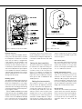
Align the loudspeakers correctly
Always place the loudspeakers so that
their acoustic axes (see figure 2) are aimed
towards the listening position. Vertical placement is preferable, as it minimises acoustical
cancellation problems around the crossover
frequency.
Drivers
Connections
The bass driver dimensions are 165 mm (6
1/2”) and 205 mm (8") for 8040A and 8050A
respectively. The long, flow optimized reflex
tube has a large cross sectional area and
terminates with a wide flare at the back of
the enclosure. The high frequency driver is a
19 mm (3/4”) metal dome on the 8040A and
a 25 mm (1") metal dome on the 8050A. Both
drivers are magnetically shielded.
Each loudspeaker is supplied with a mains
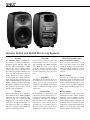
cable and an operating manual. Before connecting up, ensure that the mains switch is off
(see figure 1). Audio input is via a 10 kOhm
balanced XLR connector, but unbalanced
leads may be used as long as pin 3 is
grounded to pin 1 of the XLR (see figure 3).
Once the connections have been made, the
loudspeakers are ready to be switched on.
Amplifiers
The amplifier unit is mounted in the rear of
the loudspeaker enclosure. The unit incorporates special circuitry for driver thermal
overload protection. Variable input sensitivity allows accurate level matching to console
output section.
Maintain symmetry
Check that the loudspeakers are placed
symmetrically and at an equal distance from
the listening position. If possible, place the
system so that the listening position is on the
centerline of the room and the loudspeakers
are placed at an equal distance from the centerline.
Minimise reflections
Acoustic reflections from objects close to the
loudspeakers like desks, cabinets, computer
monitors etc. can cause unwanted colouration
and blurring of the sound image. These can
be minimised by placing the loudspeaker clear
of reflective surfaces. For instance, putting the
loudspeakers on stands behind and above the
mixing console usually gives a better result
than placing them on the meter bridge.
Figure 2. Location of the acoustic axis
Cable
RCA
(Source)
Figure 1. Amplifier panel layout of the 8040A
Minimum clearances
Sufficient cooling for the amplifier and functioning of the reflex port must be ensured if
the loudspeaker is installed in a restricted
space such as a cabinet, or integrated into
a wall structure. The surroundings of the
loudspeaker must always be open to the
listening room with a minimum clearance of
5 centimeters (2") behind, above and on both
sides of the loudspeaker. The space adjacent
to the amplifier must either be ventilated or
sufficiently large to dissipate heat so that the
ambient temperature does not rise above
35 degrees Celsius (95°F).
Mounting options
The vibration insulating Isolation Positioner/
Decoupler™ (Iso-Pod™) table stand allows
tilting of the loudspeaker for correct alignment of the acoustic axis. The stand can be
attached to three mounting points allowing
vertical and symmetrical horizontal positioning (see figures 1 and 4).
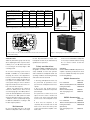
Genelec 8040A and 8050A can be fitted
to Omnimount® Series 30 (8040A) and 60
(8050A) and König & Meyer loudspeaker
mounts on two sets of M6x10 mm threaded
holes on the back of the enclosure. On the
base of the enclosure is an M10x10 mm
Screen
XLR
(Speaker)
Figure 3. RCA to XLR cable
threaded hole which can be used for securing the loudspeaker to its base. Do not use
this thread for mounting the loudspeaker on
a microphone stand which has a 3/8" UNC
thread.
Setting the input sensitivity
The input sensitivity of the loudspeakers can
be matched to the output of the mixing console, or other source, by adjusting the input
sensitivity control on the rear panel (see
figure 1). A screwdriver is needed for the
adjustment. The manufacturer’s default setting for this control is -6 dBu (fully clockwise)
which gives an SPL of 100 dB @1m with
-6 dBu input level.
Setting the tone controls
The frequency response of the system
may also have to be adjusted to match the
acoustic environment. The adjustment is
carried out by setting the three tone control switch groups "treble tilt", "bass tilt"
and "bass roll-off" on the rear panel of the
amplifier. There is also a special "desktop
low frequency" tone control which gives an
attenuation of 4 dB at 160 Hz to compensate the effect of a mixing console, desk or
other reflective surface between the listener
and the loudspeaker. The factory settings
for these controls are all "OFF" to give a flat
anechoic response.
Bass roll-off control
Bass roll-off (first switch group from the left)
affects the low frequency roll-off of the loudspeaker and attenuates its energy output
near the cut-off frequency. Attenuation levels
of -2, -4 or -6 dB can be selected.
Desktop low frequency control
The desktop low frequency control (fourth
switch of first switch group from the left)
attenuates the bass frequencies around
160 Hz by 4 dB (see figures 8 and 10). This
feature is designed to compensate for the
boost often occurring at this frequency range
when the loudspeaker is placed upon a meter
bridge, table or similar reflective surface.
Bass tilt control
The bass tilt control switches (second switch
group from the left) offer three attenuation
levels for the bass response below 800 Hz,
usually necessary when the loudspeakers are placed near room boundaries. The
attenuation levels are -2 dB, -4 dB and
-6 dB.
Speaker Mounting Position
Treble tilt
Bass tilt
Bass roll-off
Desktop LF
Flat anechoic response
None
None
None
None
Free standing in a damped
room
None
-2 dB
None
None
Free standing in a
reverberant room
None
-4 dB
None
None
Near field on a reflective
surface
None
-2 dB
None
-4 dB
In a corner
None
-4 dB
-4 dB
None
Figure 5. Omnimount type
wall mount
Table 1. Suggested tone control settings in some typical situations
Figure 4. The Iso-Pod™ can also be attached to the side of the enclosure for
horizontal mounting.
Treble tilt control
Treble tilt (third switch group from the left)
allows adjusting the treble response above
5 kHz by +2, -2, or -4 dB, which can be used
for correcting an excessively bright or dull
sounding system.
An acoustic measuring system such as
MLSSA or WinMLS is recommended for
analyzing the effects of the adjustments,
however, careful listening with suitable test
recordings can also lead to good results if a
test system is not available. Table 1 shows
some typical settings in various situations.
Figures 8 and 10 show the effect of the controls on the anechoic response.
Always start adjustment by setting all
switches to "OFF” position. Then set only
one switch per group to the "ON" position to
select the desired adjustment. If more than
one switch is set to "ON" (within one switch
group) the attenuation value is not accurate.
Measure or listen systematically through
the different combinations of settings to find
the best frequency balance.
Maintenance
No user serviceable parts are to be found
within the loudspeaker cabinet or the ampli-
Figure 6. K&M type
wall mount
Figure 7. Carrying bag for a pair of 8040A loudspeakers.
fier unit. Any maintenance or repair of the
loudspeaker should only be undertaken by
qualified service personnel.
Safety considerations
5. Free flow of air behind the loudspeaker
is necessary to maintain sufficient cooling.
Do not obstruct airflow around the
loudspeakers.
Although the 8040A and 8050A have been
designed in accordance with international
safety standards, to ensure safe operation
and to maintain the loudspeaker under safe
operating conditions, the following warnings
and cautions must be observed:
WARNING!
Genelec 8040A and 8050A loudspeakers are
capable of producing sound pressure levels
in excess of 85 dB, which may cause permanent hearing damage.
1. Servicing and adjustment must only
be perfor med by qualified ser vice
personnel. The loudspeaker must not be
opened.
2. Do not use this product with an
unearthed mains cable as this may lead to
personal injury.
3. To prevent fire or electric shock, do not
expose the unit to water or moisture. Do
not place any objects filled with liquid,
such as vases on the loudspeaker or near
it.
4. Note that the amplifier is not
completely disconnected from the AC
mains service unless the mains power
cord is removed from the amplifier or the
mains outlet.
Floor stand black
Wall mount black (Omnimount)
Ceiling mount black (Omnimount)
Wall mount black (K&M)
Soft carrying bag for two
monitors
8040A Accessories
Order code
8000-400
8040-404-B
8040-405-B
8000-401
8040-420
8050A Accessories
Floor stand black
Wall mount black (Omnimount)
Ceiling mount black (Omnimount)
Soft carrying bag for one
monitor
Order code
8000-400
8050-404-B
8050-405-B
8050-420
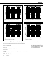
Figure 8. The curves above show the effect of the “bass tilt”,
“treble tilt”, “desktop low frequency” and “bass roll-off” controls
on the free field response of the 8040A.
Figure 9. The upper curve group shows the horizontal directivity
characteristics of the 8040A measured at 1 m. The lower curve shows
the system's power response.
Figure 10. The curves above show the effect of the “bass tilt”,
“treble tilt”, “desktop low frequency” and “bass roll-off” controls
on the free field response of the 8050A
Figure 11. The upper curve group shows the horizontal directivity
characteristics of the 8050A measured at 1 m. The lower curve shows
the system's power response.
EC Declaration of Conformity
This is to certify that Genelec Monitoring Systems 8040A and 8050A conform to the following standards:
Safety:
EN 60065 / IEC 60065:1998 6th Edition
EMC:
EN 55013: (2001)
EN 55020: (1994), A11: (1996), A12: (1999), A13: (1999), A14: (1999)
EN 61000-3-2 (2000)
EN 61000-3-3 (1995)
The product herewith complies with the requirements of The Low Voltage Directive73/23/EEC, EMC Directive 89/336/EEC
and 93/68/EEC
Signed:
Position:
Date:
Ilpo Martikainen
Managing Director
20-April-2004
Guarantee
Genelec 8040A and 8050A are supplied with
one year guarantee against manufacturing
faults or defects that might alter the performance of the loudspeakers. Refer to supplier
for full sales and guarantee terms.
8040A and 8050A Operating Manual
system specifications
crossover Section
8040A
8050A
Lower cut-off frequency, -3 dB
Upper cut-off frequency, -3 dB
≤ 45 Hz
≥ 21 kHz
≤ 35 Hz
≥ 21 kHz
Free field frequency response of
system (± 2.0 dB)
48 Hz - 20 kHz
38 Hz - 20 kHz
Maximum short term sine wave
acoustic output on axis in half
space, averaged from 100 Hz to
3 kHz
@1m
@ 0.5 m
≥ 105 dB SPL
≥ 111 dB SPL
≥ 110 dB SPL
≥ 116 dB SPL
Maximum long term RMS acoustic
output in same conditions with IEC
weighted noise (limited by driver
unit protection circuit) @ 1 m
≥ 99 dB SPL
≥ 101 dB SPL
Maximum peak acoustic output
per pair above console top, @ 1
m from the engineer with music
material
≥ 115 dB SPL
≥ 120 dB SPL
Self generated noise level in free
field @ 1m on axis (A-weighted)
≤ 10 dB
≤ 10 dB
<2%
< 0.5 %
<2%
< 0.5 %
Drivers:
Bass
Treble
Both drivers are
magnetically shielded
165 mm (6 1/2")
19 mm (3/4")
metal dome
205 mm (8")
25 mm (1")
metal dome
Weight:
8.6 kg (18.9 lbs)
12.7 kg (28 lbs)
Dimensions:
Height (without table support
Height (including table support)
Width
Depth
350 mm (13 13/16“)
365 mm (14 3/8“)
237 mm (9 3/8“)
223 mm (8 13/16“)
433 mm (17 1/16")
452 mm (17 13/16")
286 mm (11 1/4")
278 mm (10 15/16")
Harmonic distortion at 90 dB SPL
@ 1m on axis
Freq. 50 to 100 Hz
> 100 Hz
8040A
8050A
Input connector XLR female
Pin 1 gnd, pin 2 +, pin 3 -
Input impedance
10 kOhm balanced
Input level for maximum short term
output of 100 dB SPL @ 1m:
Adjustable from +6 to -6 dBu
Crossover frequency, Bass/Treble
3.0 kHz
1.8 kHz
Treble tilt control operating range in
2 dB steps
From +2 to -4 dB &
MUTE @ 15 kHz
From +2 to -4 dB &
MUTE @ 15 kHz
Desktop low frequency control
operating range
-4 dB @ 160 Hz
-4 dB @ 160 Hz
Bass roll-off control operating
range in 2 dB steps
From 0 to -6 dB
@ 45 Hz
From 0 to -6 dB
@ 35 Hz
Bass tilt control operating range in
2 dB steps
From 0 to -6 dB @
100 Hz & MUTE
From 0 to -6 dB @
100 Hz & MUTE
The 'CAL' position is with all tone controls
set to 'off' and the input sensitivity control
to maximum (fully clockwise)
Amplifier Section
8040A
8050A
90 W (8 Ohm load)
150 W (6 Ohm load)
90 W (8 Ohm load)
120 W (8 Ohm load)
Amplifier system distortion
at nominal output
THD
SMPTE-IM
CCIF-IM
DIM 100
≤ 0.05 %
≤ 0.05 %
≤ 0.05 %
≤ 0.05 %
≤ 0.05 %
≤ 0.05 %
≤ 0.05 %
≤ 0.05 %
Signal to Noise ratio, referred to
full output
Bass
Treble
≥ 100 dB
≥ 100 dB
≥ 100 dB
≥ 100 dB
Bass amplifier short
term output power
Treble amplifier short
term output power
Long term output power is limited
by driver unit protection circuitry
Mains voltage
100, 120, 220 or 230 V
according to region
Voltage operating range
±10 %
±10 %
Power consumption
Idle
Full output
10 VA
110 VA
10 VA
170 VA
www.genelec.com
Genelec Document D0003R001a Copyright Genelec Oy 2.2005-. All data subject to change without prior notice
International enquiries:
In the U.S. please contact:
In China please contact:
In Sweden please contact:
Genelec, Olvitie 5
Genelec, Inc., 7 Tech Circle
Beijing Genelec Audio Co. Ltd.
Genelec Sverige
FIN-74100, Iisalmi, Finland
Natick, MA 01760, USA
Jianwai SOHO, Tower 12, Room 2306
Box 5521, S-141 05 Huddinge
Phone +358 17 83881
Phone +1 508 652 0900
39 East 3rd Ring Road
Phone +46 8 449 5220
Fax +358 17 812 267
Fax +1 508 652 0909
Chaoyang District, Beijing 100022, China
Fax +46 8 708 7071
Email [email protected]
Email [email protected]
Phone +86 0 5869 7915
Email [email protected]
Fax +86 10 5869 7914