1
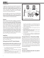
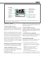
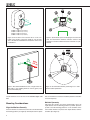
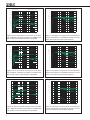
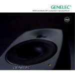
Operating Manual
8260A, 8351A, 8250A and 8240A
Introduction
Congratulations and a thank-you for the purchase of this Genelec SAM system. All Genelec SAM systems are designed to integrate easily into the digital production environment. There are
several ways to configure and operate SAM systems for a wide
variety of high quality audio applications. The SAM monitors
also have analog inputs, making them versatile and intelligent
replacements for standard analog monitors.
GLM
NETWORK
GLM
NETWORK
GLM
NETWORK
USB
MICROPHONE
This manual addresses the setup and use of the 8240A, 8250A,
8351A and 8260A SAM monitors in stand-alone mode without
the Genelec Loudspeaker Manager GLM™ and the proprietary
Genelec monitor control network. Use with the GLM™ is described in the GLM™ System Operating Manual.
System
Genelec 8240A, 8250A, 8351A and 8260A are designed for
precise monitoring of 24 bit/192 kHz AES/EBU digital audio signal or line level analog audio signal. They are fully compatible
with Genelec Loudspeaker Manager GLM™ and the proprietary
Genelec monitor control network, and Genelec 7260A, 7270A
and 7271A SAM Subwoofers, but can also be used independently of these. The 8240A, 8250A, 8351A and 8260A feature
high SPL output, low colouration and broad bandwidth in a small
enclosure size. They are suitable for a wide variety of tasks,
such as near field monitoring, mobile vans, broadcast and TV
control rooms, multichannel sound systems and home studios.
The Minimum Diffraction Enclosure™ (MDE™), advanced Directivity Control Waveguide™ (DCW™) and Minimum Diffraction Coaxial (MDC™) technologies provide excellent frequency
balance even in difficult acoustic environments.
Amplifiers
The amplifier unit is mounted in the rear of the monitor enclosure.
The unit incorporates special circuitry for driver thermal overload
protection. Variable input sensitivity allows accurate level matching to console output section.
Setting Up the GLM™ Control Network
Although the 8240A, 8250A, 8351A and 8260A can be used
without the GLM™ software and control network, they only reach
their full potential when set up and calibrated using the GLM™
software. The setup is fast and consists of the following steps:
1.
2.
3.
4.
2
Run a CAT5 (RJ45) cable from the monitor control network
to the next monitor (see Figure 1).
Run the final cable to control network input of the GLM
Adapter device.
Connect the GLM Adapter device to your computer USB
connector. The cable is a part of the GLM User Kit.
Place the Genelec measurement microphone at the listen-
LISTENING
POSITION
Figure 1. GLM control network cabling
5.
6.
7.
8.
ing location of the engineer, on a stand, with the microphone
pointing upwards and the microphone top at the height of the
engineers ear in normal working position. The microphone is
a part of the GLM User Kit.
Run the microphone cable to the microphone input in the
GLM Adapter device.
Download GLM software at the Genelec web site (www.
genelec.com). Install the GLM software.
Follow the GLM software instructions to measure and set
up your monitors.
If you plan to not use a computer for controlling the monitors, use the GLM software to write the setting into the monitors (“Store the Settings”).
Using the Monitors in Stand-Alone Mode
When the monitors are not connected to a Genelec monitor control network, they operate in the stand-alone mode. However, settings made with the Genelec Loudspeaker Manager software can
be saved into each monitor and applied even when the network
is disconnected by setting switch 1 “STORED/MANUAL CONTROL” on switch group 2 of each monitor to position “STORED.”
All issues concerning use with the network are explained in detail
in the System Operating Manual provided with the GLM™ Loudspeaker Manager software kit.
Connections
Each monitor is supplied with a mains cable, one 5 m GLM network cable and an operating manual. Before connecting up, ensure that the mains switch is off.
Mains power
switch
Stand-alone user
interface level control
-8
-6
-4
-2
-10
ON
OFF
1
-12
2
SWITCH
1
BASS
ROLL-OFF
BASS
TILT
12V Remote
connector
(8260A only)
TREBLE
TILT
-4 dB
160 Hz
+2 dB -4 dB
ON
OFF
dB
STORED AES/EBU CH. DRIVER MUTE SYSTEM LVL.
-10
-20
A
B
WF COAX
ON
OFF
-2 dB -4 dB -2 dB -4 dB
Mains input
connector
DESKTOP
-6 dB
-6 dB
MAINS INPUT 230 V~
50 / 60 Hz 330 W
SERIAL NUMBER
-2 dB
12 V
REMOTE
0
SWITCH
2
-30
dB
MANUAL
CTRL
ON + ON
OFF + OFF
DIGITAL IN
AES/EBU
SUM A AND B
DIGITAL THRU
AES/EBU
Stand-alone user
interface switch
groups 1 and 2
ANALOG
IN
8260A DSP TRI-AMPLIFIED
MONITORING SYSTEM
MAGNETICALLY SHIELDED
www.genelec.com
MADE IN FINLAND
292-8260T-6
GLM Control
Network
connectors
Analog input connector
Digital Thru connector
Digital input connector
Figure 2. Connectors and controls on the back panel of a 8260A. The 8351A is similar. 8240A and 8250A share the same
layout but without the 12 V trigger voltage connector.
“MAINS INPUT” Connector
Connect the mains supply to this connector.
“DIGITAL IN AES/EBU” Connector
Use this female XLR connector for AES/EBU formatted digital
audio input signals. This input is selected automatically when a
valid digital audio signal is present, and overrides the analog input.
Depending on the digital hardware, transmission of a 192 kHz
sample rate is achieved using a double speed, single channel/
cable interface. This is called dual-wire mode. In this case one
cable per channel is used and no channel selection is required.
Dual-wire mode is automatically detected by the input stage.
If the digital source device has a volume fader that controls the
digital level, it may be advantageous to lower the level control
either on the computer interface or on the monitor’s back panel
controls, which in turn will force the use of more of the digital [bit]
resolution in the volume control.
level is +7.0 dBu RMS on models 8240A and 8250A and +22.0
dBu RMS on models 8351A and 8260A. When A/D converter
input clip occurs the front panel light turns momentarily red, indicating the overload condition.
“CONTROL NETWORK” Connectors
Use these RJ-45 sockets to connect the monitor to the proprietary Genelec Loudspeaker Manager™ (GLM™) network only.
This connector is not Ethernet LAN compatible. Do not connect
to Ethernet LAN.
“12 V REMOTE” Connector (8260A only)
You can set up remote controlled powering up and down of the
8260A with 12 V voltage connected to this connector. The minimum current needed to actuate this function is 70 mA.
Front Panel Warning Light
Normally the light on the front panel of a SAM monitor is green,
indicating that the monitor is in normal operational mode.
The overload light (red) is activated by several events:
If the digital inputs are used, all audio outputs are referenced to 0
dBFS (digital Full Scale, the largest level that may be represented in the AES/EBU signal). These monitors produce 100 dB SPL
at 1 meter in free space for a digital input signal of –30 dB FS.
“DIGITAL THRU AES/EBU” Connector
This male XLR carries an unaltered copy of the digital signal fed
into the “DIGITAL IN AES/EBU” connector. It can be used for
daisy-chaining up to four monitors together.
“ANALOG IN” Connector
Use this connector for analog audio signals. The maximum input
• exceeding the maximum input range of the analog input
• the digital input level is less than 0.1 dB from the digital full
scale
• exceeding the output capacity of the power amplifier
(clipping in the power amplifier) and thermal
overload of the power amplifier or drivers (thermal
protection has activated)
• an error is detected in the AES/EBU audio data
If a red warning light appears, turn the analog source down! If
the levels are already modest and a digital signal is being used,
3
>0
,7 m
h
ACOUSTIC
AXIS
8240A: h=240 mm (9 7/16 in)
8250A: h=290 mm (11 1/2 in)
8351A: h=235 mm (9 1/4 in)
8260A: h=448 mm (17 5/8 in)
Figure 3. The location of the acoustic axis is on the centerline of the monitor at the given height “h”. The acoustic
axis of the 8351A and 8260A is located at the center of the
coaxial driver.
m
Min 5 c
Max
60 cm
Figure 4. Symmetrical layout and keeping the acoustic axis
clear from obstructions minimizes reflection surfaces and
maintains accurate localisation because reflections are symmetrical.
Avo
> 60 cid
m
Figure 5. Recommended distances from a single wall to the
front baffle of free-standing monitors. Correct (green) and
not recommended (red).
Figure 6. Recommended monitor positioning for 5.1 multichannel audio reproduction
ensure that there are no bit errors in the AES/EBU digital audio
data.
able, as it minimises acoustical cancellation problems around the
crossover frequency.
Mounting Considerations
Align the Monitors Correctly
Place the monitors so that their acoustic axes are aimed towards
the listening position (see Figure 3). Vertical placement is prefer4
Maintain Symmetry
Check that the monitors are placed symmetrically and at an
equal distance from the listening position. If possible, place the
system so that the listening position is on the centerline of the
room and the monitors are placed at an equal distance from the
centerline (See Figure 4).
Minimise Reflections
Acoustic reflections from objects close to the monitors like desks,
cabinets, computer monitors etc. can cause unwanted colouration and blurring of the sound image. These can be minimised by
placing the monitor clear of reflective surfaces. For instance, putting the monitors on stands behind and above the mixing console
usually gives a better result than placing them on the meter bridge.
Symmetrical positioning of the reflective objects is also important
in order to maintain a balanced soundstage (See Figure 4).
Figure 7. System Level rotary control
Low Frequency Cancellations
In general, when a monitor’s front baffle is more than 0.3 meters
(1 foot) away from the wall behind the monitor, a reflection from
this wall can cause a cancellation of low frequencies and hence
reduction of bass output. Distances between 1 and 2.2 meters
(3-7 ft.) should be avoided (See Figure 5).
As a rule of thumb, the lower the low frequency cut-off the further
away the monitor must be placed from the wall in order to avoid
this phenomenon.
Distances to the ceiling and other walls may be shorter than the
distance to the wall behind a monitor. Reflections from these surfaces may be important and should also be considered
Operating Environment
These monitors are designed for indoor use only. The permissable ambient temperature is 15-35 degrees Celsius (50-95°F) and
permissable relative humidity between 20% and 80%. Humidity condensation on the product is not allowed during use. If the
product has been stored or transported in a cool environment
and then taken into a warm room, it must be allowed to warm up
completely before connecting to mains power.
Figure 8. Switch Group 1
can be used for securing the monitor to its base. Do not use this
thread for mounting the monitor on a microphone stand which
has a 3/8” UNC thread. A wide variety of ceiling and wall mounts
are available through your Genelec dealer.
Setting the Input Sensitivity
The monitor level sensitivity functions for both analog and digital
input. The sensitivity can be matched by adjusting the rotary Level control together with the System Level switches located in the
switch group 2. (switches 6 and 7). The switches provide attenuation levels of -10 dB (sw. 6 ON), -20 dB (sw. 7 ON) and -30 dB (both
switches ON) The combined attenuation ranges from 0 to -42 dB.
Functions On Switch Group 1
(Tone Controls)
Sufficient cooling for the amplifier and functioning of the reflex
port must be ensured if the monitor is installed in a restricted
space such as a cabinet, or integrated into a wall structure. The
surroundings of the monitor must always be open to the listening
room with a minimum clearance of 5 centimeters (2”) behind,
above and on both sides of the monitor. The space adjacent to
the monitor must either be ventilated or sufficiently large to dissipate heat so that the ambient temperature does not rise above
35 degrees Celsius (95°F).
Switch group 1 (the upper switch group) comprises the tone
controls that can adjust the frequency response of the system in
stand-alone mode to match the acoustic environment.
Mounting Options
The vibration insulating Isolation Positioner/Decoupler™ (IsoPod™) table stand allows tilting of the monitor for correct alignment of the acoustic axis. The stand can be attached to three
mounting points allowing vertical and symmetrical horizontal
positioning.
The controls are labelled “TREBLE TILT”, “BASS TILT”, “BASS
ROLL-OFF” and “DESKTOP”. The factory settings for these controls are all “OFF” to give a flat anechoic response. Note that these
controls have no effect when switch 1 “STORED/MANUAL CONTROL” on switch group 2 is set to “STORED” or when the monitor
is connected to the Genelec monitor control network.
Genelec 8240A, 8250A, 8351A and 8260A can be fitted to König
& Meyer monitor mounts on two sets of M6x10 mm threaded
holes on the back of the enclosure. On the base of the 8240A
and 8250A enclosure is an M10x10 mm threaded hole which
The use of an acoustic measurement system is recommended to
analyze the effects of the adjustments, however, careful listening
with suitable test recordings can also lead to good results if a test
system is not available. Start adjustment by setting all switches
Please note that the GLM software allows a much more versatile
and precise set of controls to be used and supports the fully
automatic system alignment feature, the Genelec AutoCal. Use
the tone control switches on the monitor only if GLM is not available for the system calibration.
5
Monitor
Mounting Position
Treble
Tilt
Bass
Tilt
Bass
Roll-Off
Desktop
Flat anechoic
response
None
None
None
None
Free standing in
a damped room
None
-2 dB
None
None
Free standing in
a reverberant room
None
-4 dB
None
None
Near field on
a reflective surface
None
-2 dB
None
-4 dB
In a corner
None
-4 dB
-4 dB
None
Figure 9. Switch Group 2
AES/EBU CH
Table 1. Suggested Tone Control settings for some typical monitor placement positions.
to “OFF” position. Measure or listen systematically through the
different combinations of settings to find the best frequency balance. See Table 1 for some typical settings.
Bass Roll-Off Control
Bass Roll-Off control (switches 1 and 2) attenuates its output
near the cut-off frequency. Attenuation levels of -2 dB (sw. 1
ON), -4 dB (sw. 2 ON) or -6 dB (both switches ON) can be selected.
Bass Tilt Control
This selects the audio channel(s) available on the AES/EBU
cable to be reproduced by the monitor. Turning both switches on
reproduces the sum of the two channels on the AES/EBU cable.
Turning both switches off mutes the monitor. When two channels
are selected, 6 dB of attenuation is automatically applied to avoid
overloading the monitor.
If the AES/EBU cable is operated in dual-wire mode, the monitor detects this situation automatically and the channel selection
switches have no effect.
Driver Mute
These two switches allow you to mute the treble driver (marking
“TW”) and bass driver (marking “WF”) independently. This may
be useful to diagnose if a transducer is faulty.
The Bass Tilt control switches (swiches 3 and 4) offer three attenuation levels for the bass response below 800 Hz, usually
necessary when the monitors are placed near room boundaries.
The attenuation levels are -2 dB, -4 dB and -6 dB.
On the 8351A and 8260A the marking “TW” is replaced with
“COAX” and this switch mutes both the treble and midrange of
the coaxial driver unit.
Desktop Low Frequency Control
These switches allow scaling down of the monitor output. The
signal sent to the “Thru” output connector is not affected. The
switches are additive, for example, “–30 dB” attenuation is
achieved by turning on the “–10 dB” and “–20 dB” switches. The
effect of these switches is combined with the effect of the rotary
level adjustment control. This results in total possible attenuation
of 42 dB, 30 dB by the system level switches and another 12 dB
by the rotary control.
The desktop low frequency control (switch 5) attenuates the bass
frequencies around 160 Hz by 4 dB. This feature is designed to
compensate for the boost often occurring at this frequency range
when the monitor is placed upon a meter bridge, table or similar
reflective surface.
Treble Tilt Control
Treble Tilt control (switches 6 and 7) allows adjusting the treble
response above 5 kHz by +2 dB, -2 dB or -4 dB, which can be
used for correcting an excessively bright or dull sounding system
or to compensate for high frequency level loss if the monitor is
placed behind a screen.
Functions On Switch Group 2
Stored / Manual Ctrl
“MANUAL CTRL” refers to controlling the monitor using the controls on the monitor’s back panel. The “STORED” refers to using
settings stored inside the memory of the monitor. These settings
are made using the GLM and the GLM Control Network. There
is additional functionality compared to that offered by the room
response correction switches on the back panel.
6
System Lvl
Using the 7000 Series Analog Subwoofers
with SAM Monitors
Please follow the steps below to integrate an analog subwoofer
into a system of SAM monitors:
• Connect cables carrying analog audio to the 7000 Series
analogue subwoofer first.
• Connect the subwoofer outputs to the analog inputs of the
SAM monitors.
• Connect the GLM Control Network to the monitors.
• Make a System Setup in GLM. It will consist of only
monitors as this is all the network can see, so suitable
Rapid Cabling Presets are “Stereo Pair (Analog)” and “5.0
Surround System (Analog)”.
• Run AutoCal and review the results to check for large dips
at or above 85 Hz. Move the monitors and repeat AutoCal if
there is a problem.
• Press “Finish”, then in the Main Page select “Menu | Store
Acoustic Settings to All Online Monitors” and close GLM.
• For each SAM monitor, turn it off, select “Stored” on the
back of each monitor to activate the internal Acoustic
Settings, and then turn it on again.
• To set the phase control on the subwoofer, connect the
Center channel output of the subwoofer to the monitor to be
used to align phase.
• Follow the instructions in the subwoofer user manual for
setting phase and level.
Maintenance
No user serviceable parts are to be found within the monitor enclosure. Any maintenance or repair of the monitor should only be
undertaken by a certified Genelec service.
Guarantee
Genelec 8240A, 8250A, 8351A and 8260A are supplied with a
two year guarantee against manufacturing faults or defects that
might alter the performance of the monitors. Refer to supplier for
full sales and guarantee terms.
Accessories
A wide selection of accessories is available for Genelec monitors. Consult the Accessories Catalogue on www.genelec.com or
your local distributor/dealer for up-to-date information.
Compliance to FCC Rules
This device complies with part 15 of the FCC Rules. Operation is
subject to the following two conditions:
• This device may not cause harmful interference, and
• This device must accept any interference received, including
interference that may cause undesired operation.
• Increase the separation between the equipment and
receiver.
• Connect the equipment into an outlet on a circuit different
from that to which the receiver is connected.
• Consult the dealer or an experienced radio/TV technician
for help.
Modifications not expressly approved by the manufacturer could
void the user’s authority to operate the equipment under FCC
rules.
Safety Considerations
Although the 8240A, 8250A, 8351A and 8260A have been designed in accordance with international safety standards, to ensure safe operation and to maintain the monitor under safe operating conditions, the following warnings and precautions must
be observed:
• Servicing and adjustment must only be performed by a
certified Genelec service. The monitor enclosure must not
be opened.
• Do not use this product with an unearthed mains cable or
a mains connection without the protective earth contact as
this may lead to personal injury.
• To prevent fire or electric shock, do not expose the unit to
water or moisture.
• Do not place any objects filled with liquid, such as vases on
the monitor or near it.
• Note that the amplifier is not completely disconnected
from the AC mains service unless the mains power cord is
removed from the amplifier or the mains outlet.
• Free flow of air behind the monitor is necessary to maintain
sufficient cooling.
• Do not obstruct airflow around the monitors.
WARNING!
These monitors are capable of producing sound pressure levels
in excess of 85 dB, which may cause permanent hearing damage.
Note: This equipment has been tested and found to comply with
the limits for a Class B digital device, pursuant to part 15 of the
FCC Rules. These limits are designed to provide reasonable protection against harmful interference in a residential installation.
This equipment generates, uses and can radiate radio frequency
energy and, if not installed and used in accordance with the instructions, may cause harmful interference to radio communications. However, there is no guarantee that interference will not
occur in a particular installation. If this equipment does cause
harmful interference to radio or television reception, which can be
determined by turning the equipment off and on, the user is encouraged to try to correct the interference by one or more of the
following measures:
• Reorient or relocate the receiving antenna.
7
Genelec Oy 8240A
d
B
r
Genelec Oy 8240A horizontal off axis response level (dBr) vs freq (Hz) 17 Jan 06
(dBr) vs freq (Hz) 17 Jan 06
100
95
90
A
85
d
B
r
DESKTOP LF
90 80
A
85
80 90
90
0° 15° 30°
85
80
45°
75
BASS TILT
60°
70
85
80
65
BASS ROLL-OFF
TREBLE TILT
60
55
20
100
50
200
500
1k
2k
5k
50
20k
10k
20
50
100
200
500
1k
5k
2k
Hz
Figure 10. The curves above show the effect of the “Bass
Tilt”, “Treble Tilt”, “Desktop Low Frequency” and “Bass RollOff” controls on the free field response of the 8240A.
Genelec Oy 8250A
d
B
r
Figure 11. The upper curve group shows the horizontal directivity characteristics of the 8240A measured at 1 m. The
lower curve shows the system’s power response.
Genelec Oy 8250A
(dBr) vs freq (Hz) 17 Jan 06
(dBr) vs freq (Hz) 17 Jan 06
100
95
90
A
20k
10k
Hz
85
d
B
r
DESKTOP LF
90 80
A
85
80 90
90
0° 15° 30°
85
80
75
BASS TILT
45°
60°
70
85
65
80
BASS ROLL-OFF
TREBLE TILT
60
55
20
50
100
200
500
1k
2k
5k
50
20k
10k
20
50
100
200
500
1k
5k
2k
Figure 12. The curves above show the effect of the “Bass
Tilt”, “Treble Tilt”, “Desktop Low Frequency” and “Bass RollOff” controls on the free field response of the 8250A.
Genelec Oy 8351A
d
B
r
A
20k
10k
Hz
Hz
Figure 13. The upper curve group shows the horizontal directivity characteristics of the 8250A measured at 1 m. The
lower curve shows the system’s power response.
Genelec Oy 8351A
dBr) vs freq (Hz) 20 Nov 2014
(dBr) vs freq (Hz) 20 Nov 2014
100
95
90
85
d
B
r
DESKTOP LF
90 80
A
85
80 90
90
0° 15° 30°
85
80
75
BASS TILT
45°
60°
70
85
65
80
TREBLE TILT
BASS ROLL-OFF
60
55
20
50
100
200
500
1k
2k
5k
20k
10k
Hz
Figure 14. The curves above show the effect of the “Bass
Tilt”, “Treble Tilt”, “Desktop Low Frequency” and “Bass RollOff” controls on the free field response of the 8351A.
8
50
20
50
100
200
500
1k
2k
5k
20k
10k
Hz
Figure 15. The upper curve group shows the horizontal directivity characteristics of the 8351A measured at 1 m. The
lower curve shows the system’s power response.
Genelec Oy 8260A
d
B
r
A
Genelec Oy 8260A
(dBr) vs freq (Hz) 12 Jan 11
(dBr) vs freq (Hz) 12 Jan 11
100
95
90
85
d
B
r
DESKTOP LF
90 80
A
85
80 90
90
0° 15° 30°
85
80
75
BASS TILT
45°
60°
70
85
65
80
TREBLE TILT
BASS ROLL-OFF
60
55
50
20
50
100
200
500
1k
2k
5k
20k
10k
20
50
100
200
500
1k
2k
Figure 16. The curves above show the effect of the “Bass
Tilt”, “Treble Tilt”, “Desktop Low Frequency” and “Bass RollOff” controls on the free field response of the 8260A.
Figure 18. 8240A horizontal directivity plot.
Figure 20. 8250A horizontal directivity plot.
5k
20k
10k
Hz
Hz
Figure 17. The upper curve group shows the horizontal directivity characteristics of the 8260A measured at 1 m. The
lower curve shows the system’s power response.
Figure 19. 8240A vertical directivity plot.
Figure 21. 8250A vertical directivity plot.
9
Figure 22. 8351A horizontal directivity plot.
Figure 23. 8351A vertical directivity plot.
Figure 24 8260A horizontal directivity plot.
Figure 25. 8260A vertical directivity plot.
95
d
B
r
A
Genelec Oy 8260A
(dBr) vs freq (Hz) 12 Jan 11
90
85
80
75
20
50
100
200
500
1k
2k
5k
10k
20k
40k
Hz
Figure 26. 8260A on-axis free field response up to 40 kHz .
10
SPECIFICATIONS
8240A
Drivers
Bass
Midrange
Treble
8250A
8351A
8260A
165 mm (61/2 in)
n/a
19 mm (3/4 in) metal dome
205 mm (8 in)
n/a
25 mm (1 in) metal dome
Dual 8 1/2 x 4 in
120 mm (5 in) Coax
Al-cone
19 mm (3/4 in) Coax
Al-dome
255 mm (10 in)
120 mm (5 in) Coax
Al-cone
19 mm (3/4 in) Coax
Al-dome
Free field frequency response of system
41 Hz - 23 kHz
(- 6 dB)
32 Hz - 23 kHz
(- 6 dB)
32 Hz - 35 kHz
(- 6 dB)
23 Hz - 40 kHz
(- 6 dB)
Accuracy of frequency response
48 Hz - 20 kHz
(± 1.5 dB)
38 Hz - 20 kHz
(± 1.5 dB)
38 Hz - 20 kHz
(± 1.5 dB)
29 Hz - 20 kHz
(± 1 dB)
Maximum peak SPL output per pair
on top of console at 1 m with music material
≥ 115 dB SPL
≥ 120 dB SPL
≥ 121 dB SPL
≥ 123 dB SPL
Maximum short term sine wave SPL output at
1 m on axis in half space, averaged as specified
(from 100 Hz to 3 kHz)
≥ 105 dB SPL
(from 100 Hz to 3 kHz)
≥ 110 dB SPL
(from 100 Hz to 3 kHz)
≥ 111 dB SPL
(from 100 Hz to 3 kHz)
≥ 113 dB SPL
Crossover frequency
3 kHz
1.8 kHz
470 Hz, 2.6 kHz
490 Hz, 2.6 kHz
Self generated noise level in free
field @ 1 m on axis (A-weighted)
≤ 10 dB
≤ 10 dB
≤ 5 dB
≤ 5 dB
Input signal
Analog
AES/EBU (single wire and dual wire)
1 XLR female (10 kOhm input load impedance)
1 XLR female (conforms to IEC 60958-4)
Output / Thru signal
AES/EBU (single wire and dual wire)
1 XLR male (conforms to IEC 60958-4)
Digital audio
Word length
Sample rate
16 - 24 bits
32 - 192 kHz
Analog input level for 100 dB SPL at 1 m
Maximum analog input signal
-6 dBu
+7 dBu
+7 dBu
+21 dBu
Control network
Type
Connection
proprietary GLMTM network
2 RJ45, CAT5 cables
GLMTM software frequency response adjustment*
Notch filters
Shelving filters
2 LF and 2 HF
2 LF and 2 HF
System calibration *
Bass amplifier output power
Midrange amplifier output power
Treble amplifier output power
(Long term output power is limited by driver
protection circuitry)
+21 dBu
4 LF and 2 HF
2 LF and 2 HF
AutoCalTM, GLMTM manual, Stand-alone
90 W
n/a
90 W
150 W
n/a
120 W
150 W
120 W
90 W
150 W
120 W
120 W
Power consumption
Idle
Full output
14 W
110 W
17 W
170 W
20 W
290 W
26 W
330 W
Dimensions
Height
Width
Depth
Height with Iso-Pod™
350 mm (1313/16 in)
237 mm (93/8 in)
223 mm (813/16 in)
365 mm (143/8 in)
433 mm (171/16 in)
286 mm (111/4 in)
278 mm (1015/16 in)
452 mm (1713/16 in)
433 mm (171/16 in)
286 mm (111/4 in)
278 mm (1015/16 in)
452 mm (1713/16 in)
570 mm (227/16 in)
357 mm (141/16 in)
347 mm (135/8 in)
593 mm (233/8 in)
Weight
9.4 kg (20.8 lb)
14.6 kg (32 lb)
19 kg (42 lb)
27.5 kg (60.5 lb)
* The notch and shelving filters adjustments, AutoCalTM and GLMTM manual system calibration features are part of the Genelec Loudspeaker Manager (GLMTM) software
11
www.genelec.com
Genelec Document D0081R001b Copyright Genelec Oy 11.2014. All data subject to change without prior notice.
International enquiries:
In the U.S. please contact:
In Sweden please contact:
In China please contact:
Genelec, Olvitie 5
Genelec, Inc., 7 Tech Circle
Genelec Sverige
Beijing Genelec Audio Co.Ltd
FIN-74100, Iisalmi, Finland
Natick, MA 01760, USA
Ellipsvägen 10B
Room 101, 1st floor
Phone +358 17 83881
Phone +1 508 652 0900
P.O. Box 5521, S-141 05 Huddinge
Fax +358 17 812 267
Fax +1 508 652 0909
Phone +46 8 449 5220
Email [email protected]
Email [email protected]
Fax +46 8 708 7071
Email [email protected]
Building 71 B33
Universal Business Park
No. 10 Jiuxianqiao Road
Chaoyang DistrictBeijing, ChinaPhone +86
(10) 5823 2014
Post code: 100015
Email [email protected]