1
Grapholas 7.5
USER MANUAL
21.08.2009
Grapholas 7.5
2 / 35
Table of Contents
1
INTRODUCTION .......................................................................................................................................... 4
2
FIRST START-UP OF THE SOFTWARE ........................................................................................................... 4
2.1
ENTERING THE LICENSE KEY................................................................................................................................. 4
2.2
SETTING THE LANGUAGE..................................................................................................................................... 4
2.3
NETWORK CONFIGURATION ................................................................................................................................ 5
3
MERGER ..................................................................................................................................................... 6
3.1
QUICK START ................................................................................................................................................... 6
3.2
THE USER INTERFACE ......................................................................................................................................... 7
3.3
TOOLBAR ......................................................................................................................................................... 8
3.3.1
3.3.2
3.3.3
3.3.4
3.3.5
3.3.6
3.3.7
3.3.9
3.4
Loading Images ................................................................................................................................. 8
Manual Cropping .............................................................................................................................. 9
Automatic Cropping ........................................................................................................................ 10
Mirroring ......................................................................................................................................... 10
Inverting .......................................................................................................................................... 11
Rotating .......................................................................................................................................... 11
Viewing Images ............................................................................................................................... 12
Sending the Job to the CDI .............................................................................................................. 13
MERGER MENU BAR ....................................................................................................................................... 13
3.4.1
3.4.2
3.4.3
3.4.4
3.4.5
3.4.6
3.4.7
3.4.8
3.4.9
3.4.10
3.4.11
3.4.12
3.4.13
3.4.14
Unloading Images ........................................................................................................................... 13
Unloading Positioned Images ......................................................................................................... 13
Selecting the Working Directory ..................................................................................................... 14
Saving the Plate .............................................................................................................................. 14
Loading the Plate ............................................................................................................................ 14
Creating a New Plate ...................................................................................................................... 14
Automatic Positioning of the Images .............................................................................................. 14
Automatic Positioning of the Images .............................................................................................. 15
Removing Images from the Working Surface ................................................................................. 15
Displaying File Names ..................................................................................................................... 15
Displaying the Parameters Window................................................................................................ 15
Printing the Display ......................................................................................................................... 16
Checking Images ............................................................................................................................. 16
Copying Images ............................................................................................................................... 16
3.5
WORKING SURFACE AND STATUS BAR ................................................................................................................. 16
3.6
SETTING THE "DRUM WINDOW" ENGRAVING PARAMETERS .................................................................................... 17
3.6.1
3.6.2
3.6.3
3.6.4
Selecting the Drum .......................................................................................................................... 18
Setting the Drum Circumference ..................................................................................................... 18
Changing the Speed ........................................................................................................................ 18
Partial Plates ................................................................................................................................... 18
Grapholas 7.5
3.6.5
3.6.6
3.6.7
3.6.8
3.6.9
3.6.10
3.6.11
3.6.12
3.6.13
3.6.14
3.7
3 / 35
Selecting the Plate .......................................................................................................................... 19
Creating a New Plate ...................................................................................................................... 19
Setting the Frame............................................................................................................................ 20
Setting the Image Distance and the Cut Marks .............................................................................. 20
Adding a Label ................................................................................................................................ 20
Defining the Image Position ............................................................................................................ 21
Overlaying Images .......................................................................................................................... 21
Entering the Grid and the Angle Manually ..................................................................................... 21
Arranging Images ("Step & Repeat") .............................................................................................. 22
Gapless Sleeves ............................................................................................................................... 22
TEMPLATES .................................................................................................................................................... 23
3.7.1
Changing Templates ....................................................................................................................... 24
3.8
JOB INFORMATION .......................................................................................................................................... 24
3.9
LOADING IMAGES VIA "DRAG & DROP"............................................................................................................... 25
3.10
BASIC MERGER SETTINGS ................................................................................................................................. 25
4
EXPOSER ....................................................................................................................................................27
4.1
STATUS DISPLAYS AND CONTROLS ...................................................................................................................... 28
4.2
VACUUM DISPLAY AND POSITION CONTROL ......................................................................................................... 28
4.3
JOB LIST ........................................................................................................................................................ 28
4.4
MACHINE CONTROLS ....................................................................................................................................... 29
4.5
STARTING A JOB .............................................................................................................................................. 29
4.6
FOCUS SEARCH ............................................................................................................................................... 29
4.7
ZERO POINT SEARCH FOR "SLEEVES"................................................................................................................... 30
4.8
UV EXPOSURE "UV INLINE" (OPTION)................................................................................................................ 30
4.9
UV BACK EXPOSURE (OPTION FOR AUTOMATON)................................................................................................. 31
4.10
CONTROL AND STATUS DISPLAY OF THE AUTOMATON ............................................................................................ 31
4.11
INTERLOCKS AND ERRORS ................................................................................................................................. 32
5
HOT KEYS...................................................................................................................................................33
6
HOTLINES ..................................................................................................................................................34
Grapholas 7.5
1
4 / 35
Introduction
LEN and TIF files are prepared for exposure on a CDI using the "Merger". It positions
the images on the printing plate, and can also rotate, mirror, crop and invert the images
as required.
The "viewer" is used to display and measure the LEN/TIF files. The angle and the
rasterization can also be measured.
The "Exposer" controls the CDI with the jobs prepared by the "Merger".
2
First Start-up of the Software
All important settings are copied over during an update.
2.1
Entering the License Key
During initial installation or when updating from an older version, the license key must
be entered to start the "Merger":
The ESKO-Service provides a serial number for this "ProductID" which needs to be
entered in the "Serial Number" field and confirmed by ENTER.
The license can be subsequently changed with the "New License" program in the
Windows start menu under "Esko - Digital Flexo Suite - System".
2.2
Setting the Language
The language can be changed with the "UI Language" program in the Windows start
menu under "Esko - Digital Flexo Suite - System".
Grapholas 7.5
2.3
5 / 35
Network Configuration
The image data can be loaded from the local hard drive, over a network release, or via
FTP. With regard to data security, transmission via FTP protocol is to be preferred over
network release.
The "User Data" path entered during installation is already released as a network drive.
To set up additional drives, run the "guinet.bat" program in the c:\bsl\ui directory.
Clicking the field below "Drive" displays the registered drives. Selecting one of these
drives calls up the entered access data. In addition, the selected drive can be deleted or
changed.
After clicking on "New", the local drive letter on this drive is shown under "Disk" and the
subdirectory is shown under "Sub directory". The name of this drive link is entered in the
"Drive Name" field. The Merger later accesses this drive via this name.
The "FTP" option is activated for an FTP connection and the IP number or the computer
name of the FTP server is entered under "Host". The user name and the password must
be entered accordingly. In addition, a name for this link must be entered under
"Drive Name".
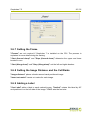
The user data for the FTP connection can be tested using the "Test" button. A new
window designated "Load Image" appears.
"OK" cancels the test and accepts the selected directory.
"Cancel" closes this window without making changes to the path.
The entered data is accepted using "Accept". "Quit" closes the drive configuration. Any
changes made are stored with "OK" .
Grapholas 7.5
3
6 / 35
Merger
The "Merger" is used to load the image data from the local hard drive or from the
network and to send it to the preselected CDI.
In addition, simple tools such as "mirror", "crop" and "rotate" are available.
3.1
Quick Start
1
Start the Merger and load the required images. They are displayed in the
image gallery (on the right).
2
Select the CDI if necessary. The CDI loads all important parameters which
are updated in the Merger.
3
Position the images on the working surface. Click on the images or the
working surface with the right mouse button to display additional
information.
4
Select the required plate. The preset speed and performance are displayed.
5
Send the job to the CDI.
Grapholas 7.5
3.2
7 / 35
The User Interface
The Merger can be divided into three areas:
Area 1:
menu bar / toolbar with icons for the most important options
Area 2:
working surface on which the images are positioned and status bar
Area 3:
"Drum Window" to set the engraving parameters
If no icons are visible, they can be activated in the "Options – Preferences - Merge
Options" menu.
Grapholas 7.5
3.3
8 / 35
Toolbar
This area contains frequently used functions:
If some required functions are not displayed, they can be activated in the basic settings.
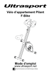
3.3.1 Loading Images
Strg/Ctrl + E
calls up a file dialog box in which the LEN or TIF files can be selected.
1. Selection of network share (e.g. FTP server).
2. Display of directories.
3. Display of files.
By pressing the "Control" or the CAPS button together with the left mouse
button, several files can be marked simultaneously; they can then be loaded
by pressing "OK". Single files can directly be loaded by double-clicking
them.
4. If only one file is selected, you can select how often this file shall be loaded.
Grapholas 7.5
9 / 35
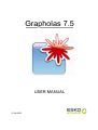
3.3.2 Manual Cropping
opens a new window in which the image can be cropped:
Starting from the frame area, a lasso can be pulled open by pressing and holding
down the left mouse button and pulling the mouse across the work surface; or the exact
lasso size can be entered in the four input fields on the right-hand side (1).
The distance between two positions in the image can be measured by pressing
and holding the left mouse button down.
Individual sections of the image can be enlarged with a square magnifier by
pressing and holding down the left mouse button and pulling the mouse across the
section of interest. The magnified image section can then be positioned using the arrow
keys on the keyboard.
displays the entire image.
Grapholas 7.5
10 / 35
performs the automatic cropping.
sets back all cutting edges.
saves the current image section as a new LEN file.
Manual cropping is not available for LEN files of the "PlatePatcher" and the
"Staggered Cut".
3.3.3 Automatic Cropping
crops unused image frame areas. No new file is created.
The edge detection also takes individual pixels into account. By placing microdots in two
separate positions (e.g. top left and bottom right), this function can be used to crop the
files to a specific size.
The distance to the "Bleed" pixels can be set in the Merger properties. If the image
contains "Staggered Cut" information, the image is cropped on this cutting line.
Several files can be marked simultaneously by pressing the "Control" button together
with the left mouse button to automatically crop these files.
Automatic cropping is not available for LEN files of the "PlatePatcher".
3.3.4 Mirroring
horizontally or vertically mirrors the selected image. A new file is
created with a "_ymir" or an "_xmir" extension.
Depending on the file size, this can take some minutes.
Several files can be marked simultaneously by pressing the "Control" button together
with the left mouse button to mirror these files.
Mirroring is not available for LEN files of the "PlatePatcher" and the "Staggered Cut".
Grapholas 7.5
11 / 35
3.3.5 Inverting
creates a negative image of the selected image. A new file is created with the
"_inv" extension. Depending on the file size, this can take some minutes.
Several files can be marked simultaneously by pressing the "Control" button together
with the left mouse button to invert these files.
Inverting is not available for LEN files of the "PlatePatcher" and the "Staggered Cut".
3.3.6 Rotating
rotates the image by 90°.
Several files can be marked simultaneously by pressing the "Control" button together
with the left mouse button to rotate these files.
Grapholas 7.5
12 / 35
3.3.7 Viewing Images
opens the "Viewer" - a very extensive image viewer:
Several files can be marked simultaneously by pressing the "Control"button together
with the left mouse button to view these files, each superimposed on top of the other, in
the "Viewer".
Click on the question mark "?" in the "Viewer" or open the installation CD to read the
detailed manual.
Grapholas 7.5
13 / 35
3.3.9 Sending the Job to the CDI
Strg/Ctrl + E
opens a dialog window in which the job name can be entered. By pressing "OK", the job
is sent to the CDI or a TIF file is created in the output directory.
3.4
Merger Menu Bar
Only the additional functions which are not listed in the toolbar are described. The menu
bar is situated above the toolbar.
3.4.1 Unloading Images
"Unload Image" (Strg/Ctrl + u) removes the selected image from the Merger. The file
is not deleted from the hard drive.
3.4.2 Unloading Positioned Images
"Remove All Positioned Images" (Strg/Ctrl + d) removes all images from the Merger
which are positioned on the working surface. The files are not deleted from the hard
drive. This is useful when the job was sent and several images are still in the queue.
Grapholas 7.5
14 / 35
3.4.3 Selecting the Working Directory
"Select Working Folder" (Ctrl + w) changes the working directory in which all images
are copied or moved during the loading process. This option is not available if images
are loaded.
3.4.4 Saving the Plate
"Save Plate" (Ctrl + s) saves the compiled images and the engraving parameters as
plate. When the compiled images are sent to the CDI, the plate is automatically saved
under the entered name.
"Save Plate as" saves the compilation under another name.
3.4.5 Loading the Plate
"Load Plate" (Ctrl + L) loads a previously saved or sent compilation with all
parameters. All currently loaded images are removed.
3.4.6 Creating a New Plate
"New Plate" (Ctrl + n) removes all images from the Merger and resets the parameters.
3.4.7 Automatic Positioning of the Images
"Auto Arrange Images" (Ctrl + a) automatically positions as many loaded images as
possible on the working surface. Beforehand, images which were already positioned on
the work surface are removed. The type of positioning can be selected in the Merger
properties.
Grapholas 7.5
15 / 35
3.4.8 Automatic Positioning of the Images
"Auto Arrange New Images" (Strg/Ctrl + h) automatically adds the loaded images to
the compilation on the working surface. Already positioned images are not removed.
3.4.9 Removing Images from the Working Surface
"Unplace all" (Strg/Ctrl + u) removes all images from the working surface. The images
are not unloaded.
3.4.10
Displaying File Names
"Display Names" shows the file names in the images positioned on the working
surface.
3.4.11
Displaying the Parameters Window
"Drum Window" displays the "drum window" if it was closed before. This window
shows all engraving parameters.
Grapholas 7.5
3.4.12
16 / 35
Printing the Display
"Print Display / Print Job Info" displays additional information and prints the working
surface.
3.4.13
Checking Images
"Check Image" checks the selected file for mistakes.
3.4.14
Copying Images
"Copy FTP File(s)" opens the same window as "Load Image" to copy the images into
the working directory. This does not load the images into the Merger.
3.5
Working Surface and Status Bar
The working surface shows the available area on the plate. If Grapholas version 7 is
installed on the CDI, it is not necessary to enter the upper and lower borders as the
entire working area is shown. If older versions are installed on the CDI, borders must be
entered to not engrave the clamping bar.
The loaded images are pulled from the right queue on the working surface by holding
down the left mouse button.
Grapholas 7.5
17 / 35
In addition, guides can be pulled from the grey frame area by holding down the left
mouse button. The images cannot be positioned in the red area. The guide can be
removed again by clicking with the right mouse button on the grey frame area.
Using the right mouse button to click the work surface displays information on the plate
size and the use of the plate.
Using the right mouse button to click the image file displays information on the image.
The status bar shows the current settings and the number of loaded images.
3.6
Setting the "Drum Window" Engraving Parameters
The "Drum Window" contains all necessary engraving parameters and additional
settings for image repetitions and additional text / space between images.
As of version 7, each CDI has a drum list in which values such as circumference, width
and maximum speeds can be entered. The circumference can no longer be changed
with the Merger. Borders need not to be entered since only the available working
surface is displayed in the Merger.
CDIs on which Grapholas up to version 5.5 MR2 is installed can be connected, but the
drum list is not included and frames must be used.
Grapholas 7.5
18 / 35
3.6.1 Selecting the Drum
"Drum:" selects the required drum if several drums (e.g. Sleeve and Drum 5080) are
registered on the CDI. This is only possible with Grapholas 7.
3.6.2 Setting the Drum Circumference
"Circumference" sets the drum circumference if a CDI is connected to Grapholas
6.2/5.5. Unintentional changing of this parameter results in faulty plates. It is advisable
that the "Lock circumference" field be blocked in the basic settings.
3.6.3 Changing the Speed
"Speed" and "Laser power" directly influence the exposure on the CDI and are
automatically set according to the plate list. The speed can be subsequently changed.
3.6.4 Partial Plates
"Partial Plate:" is used to expose partial plates. The vacuum check on the CDI is
deactivated. In addition, the speed is limited to a safe value depending on the plate
thickness.
"Height" and "Width" are the heights and widths of the plate to be exposed.
Grapholas 7.5
19 / 35
3.6.5 Selecting the Plate
"Plate Type": is used to select the plate type. The "Thickness" is important here. The
exposure parameters and the plate thickness are stored in this list.
The yellow point in front of the name of the plate symbolises control via the laser
energy. The parameters for exposure are automatically set depending on the image
resolution and the drum or the circumference of the drum or sleeve.
Only the plate types which fit the selected drum are displayed.
3.6.6 Creating a New Plate
"Edit Plate List" opens a new window in which a new plate can be stored with "New".
"Name" determines the display names in the plate list and "Thickness" defines the
thickness of the plates. To assign the right drum to the right plate, the type of medium
(film – plate – sleeve – metalback) must be selected.
You can either set the "Speed" and the "Laser power" or the "Laser Energy" by clicking
on "Energy".
"Accept" accepts the set parameters. "Quit" closes the window.
After adding or changing a plate, the exposer on the CDI must be restarted.
Grapholas 7.5
20 / 35
3.6.7 Setting the Frame
"Frames" are not required if Grapholas 7 is installed on the CDI. The process is
explained in more detail during the training.
"Start (Around drum)" and "Stop (Around drum)" determine the upper and lower
borders in mm.
"Start (Along drum)" and "Stop (Along drum)" set the left and rights borders.
3.6.8 Setting the Image Distance and the Cut Marks
"Image distance" places a border around each positioned image.
"Insert cut marks" inserts cut marks for each image.
3.6.9 Adding a Label
"Use Label" adds a label to each marked image. "Vertical" rotates this label by 90°
and positions it on the left side of the image. "Font" sets the font size.
Grapholas 7.5
3.6.10
21 / 35
Defining the Image Position
"X Position" and "Y Position" change the position of the selected image.
"Set Position" is used to set the position of the image.
3.6.11
Overlaying Images
If you activate "Overlay", the images can also be placed one on top of the other.
3.6.12
Entering the Grid and the Angle Manually
The rasterization and the angle of the image can be entered using "Linecount..." if the
image does not already have this information. Images without this information are
marked in red on the work surface. "Testform" marks test wedges if these are not to be
sent to the customer.
If highlighted in grey, these two fields are irrelevant for the selected CDI.
Grapholas 7.5
3.6.13
22 / 35
Arranging Images ("Step & Repeat")
For the marked image, "Repeat" in "Across / Around:" sets the number of vertical
repetitions with "Around", and sets the number of horizontal repetitions with "Across".
"Gap" additionally adds a gap between each repetition.
3.6.14
Gapless Sleeves
"Sleeve" is only available in the gapless exposure. For this purpose, a sleeve must be
selected in the drum list or the sleeve option must be enabled by the service.
"Seamless" is used to prepare an image for the exposure on a sleeve. If the image is
smaller than the circumference, a gap is automatically added. "Offset" moves the
beginning of the image on the circumference. "Drop" and "Stagger" are only activated
if an image was reproduced using the width ("Step & Repeat").
Grapholas 7.5
3.7
23 / 35
Templates
If these functions are not displayed, they can be activated in the basic settings.
A template is a "mask" in which the positions, image sizes and plate parameters are
stored in order to position images quickly at a later time. This working mode is
interesting for register pinwheels such as, e.g. for Letterpress.
To create a template, you first position the required images onto the work area and then
select the plate type. This compilation is then saved using "Save Template".
Do NOT crop or rotate the images!
The template is loaded using "Use Template". The stored positions and sizes are shown
as yellow fields. The images must be reloaded and then positioned in the yellow fields.
The images must be within a certain size tolerance in order to be assigned to a field.
"Edit Template" makes it possible to edit the currently loaded template in the Merger
and then save it with the changes made.
Grapholas 7.5
24 / 35
3.7.1 Changing Templates
Templates can also be changed using "Correct Template" without the Merger.
The template is loaded using "File – Load Plate".
The position of single or multiple images can be changed horizontally using "Across"
and vertically using "Circumference". The value is entered absolute or relative to the
current position, ENTER is then pressed and the value is set using "Set Position".
Multiple images can be marked by pulling a square lasso around the required images
with the left mouse button pressed.
The template is stored by clicking the "Save" button.
3.8
Job Information
An HTML or XML file with the respective job name is created in the "HTM Target
Folder" output directory for each sent job. All important information concerning the job is
stored in that directory. The output directory "d:\files\output\preview" is preset.
Only the dimensions and areas of the original images are displayed in this file.
Additional frames are not taken into account here.
Grapholas 7.5
3.9
25 / 35
Loading Images via "Drag & Drop"
Image files (LEN and TIF) can directly be dragged into the right image bar of the
"Merger" from the Windows Explorer. First, the data is copied into the working directory,
then it is loaded. If the "Strg/Ctrl" key is pressed at the same time, the files are always
copied.
3.10 Basic Merger Settings
Grapholas 7.5
26 / 35
"Units" switches between "mm" and "inch".
"Digits" and "Post colon" set the amount of numbers and/or decimal points.
"Lock circumference" blocks entry of the drum circumference in order to avoid
unintentionally changing it.
"Check Images before start" checks the images of all outgoing jobs.
"File Copy Method" sets the behavior while loading images. The "Copy" setting is used
to copy files, if "Move" is selected, the files are deleted from the source directory.
"Bleed" sets the border during automatic cropping.
"Show Ruler" activates or deactivates the ruler. This setting affects the Merger.
"Autoplace mode:" sets the method (mode) of how the images are automatically
arranged on the work surface. "Permutation", "Random", "Sorted", "MDB" and "FFDH"
can be selected as mode. MDB arranges the images which allows for easy cropping
later on.
"Auto Rotate" activates the rotation of up to 7 images during automatic positioning. The
selection of these images is via the aspect ratio using "Rotate Level".
"Plugin Selection": This is where you can activate or deactivate options for the Digital
Flexo Suite.
"Merge Options": To organise the surface more clearly, the functions which are not
required can be activated or deactivated.
In the "Folder" window, the preset output directories can be changed.
The job information is saved in the "HTM Target Folder" directory.
The Merger must be restarted after any change.
Grapholas 7.5
4
27 / 35
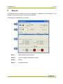
Exposer
The Exposer starts the jobs sent from the Merger. In addition, a focus search or, for
sleeves, a zero point search can be performed here.
The Exposer is divided into four areas:
Area 1:
status displays and controls
Area 2:
vacuum display and position control
Area 3:
job list
Area 4:
machine controls
Grapholas 7.5
4.1
28 / 35
Status Displays and Controls
The CDI status is displayed with icons. Depending on the version, the status of the UV
exposure and the automaton can be displayed here.
If several drums are registered, the currently used drum can be selected in the "Drum"
field.
When using "Advance Cantilver", an automatic search for the clamping bar is carried
out as soon as "Drum Sleeve" is selected.
4.2
Vacuum Display and Position Control
"Engraving Axis" displays the current position of the laser. The desired start position for
the imaging process is entered in the "Position" field and run by pressing [ENTER].
"Home" moves the laser back to 1 mm.
"Pressure" displays the vacuum. For full plates, a vacuum of over 900 mbar is required.
The engraving process cannot be started unless the required value has been reached.
For partial plates, the vacuum is not analysed since the speed was reduced to a safer
value.
4.3
Job List
The "Job" name, the "Plate" type and the job "Status" are displayed for each job:
• ready
Completed job.
• run-busy Imaging has started.
• failed
Error when transferring data to the Exposer.
Information on "Width", "Height", "Speed", "Laser power", "Circumference" and "Drum"
is displayed in the "Job Info:" field for the selected job.
"To top" can be used to move the job selected to the top position for imaging. "Remove"
deletes the selected job.
A click of the right mouse button on the job shows additional information.
Grapholas 7.5
4.4
4.5
29 / 35
Machine Controls
• Start
Start the selected job.
• Pause
Stop the current exposure.
• Cancel
Cancel the current exposure.
Starting a Job
The desired job is selected from the list and run with the "Start" button. The job's
remaining time is displayed on the bottom of the status bar.
"Pause" stops the engraving. "Start" can be used to resume it, but may cause a seam in
the imaging. "Cancel" cancels the job.
When the exposure is completed, a dialog window is displayed where the job can be
deleted or put back into the queue.
4.6
Focus Search
The focus search is used to set the distance of the laser to the plate in place. The focus
setting is very important for achieving the optimum imaging quality:
Grapholas 7.5
30 / 35
The plate in place has to be selected under "Plate Types". The start of the focus search
is set using "Start (Around drum)".
For partial plate mode, the "Partial Plate" option has to be activated.
The focus search is lined up as new job in the Exposer by clicking on "OK" and started
as normal job in the Exposer.
The deactivated input fields can be enabled using the "Advanced" button.
When the focus search is ended, dialog box "FocusDialog" is displayed in which the
position of the thinnest line in the focus field "Best Track" has to be entered. "OK"
changes the focus setting in line with the input.
4.7
Zero Point Search for "Sleeves"
To determine the zero point on a sleeve, the job to be exposed is lined up in the
Exposer first and then the zero point search is started via "Options". The parameters
are displayed in a new window; an "Offset" can be entered in advance:
By pressing "OK", the job "Zero_esko_special" is lined up in the Exposer. A ruler will be
engraved on the sleeve. The zero point on the ruler corresponds to the zero point of the
sleeve.
4.8
UV Exposure "UV Inline" (Option)
"UV Inline" exposes the upper side of the plates. This function can be activated or
deactivated via "UV Unit". When the CDI is restarted, the UV exposure is automatically
activated unless the external cooler is switched off.
The service technician adapts the UV parameters for the desired plate types. If no UV
parameters are adapted for some plates, they will be started without UV exposure. If the
UV unit is deactivated, a warning is displayed when starting the exposure if UV
parameters are available for this plate type.
Grapholas 7.5
31 / 35
The status of the UV unit is displayed with the following icons:
UV unit activated
UV exposure
osure activated
4.9
UV Back Exposure
osure (Option for Automaton)
n)
The UV back exposure is available as an option for the automaton. This function can be
activated or deactivated via "UV Unit". When the CDI is restarted,
arted, the UV back
exposure is automatically activated.
ctivated.
The service technician adapts
apts the UV parameters for the desired plate types. If no UV
parameters are adapted forr some plates, they will be started withoutt UV back exposure.
The status of the UV back exposure unit is displayed with the following
ing icons:
UV backk exposure unit activated
UV backk exposure activated
4.10 Control and Status Display of the Automaton
ton
Under "APL", the automaticc function of the automaton can be activated
vated or deactivated.
The status of the automaton
n is displayed with the following icons:
No plate
e loaded.
The plate
te is located on the drum.
The plate
te is located in the tray.
The plates
tes are located on the drum and in the tray.
ay.
Grapholas 7.5
32 / 35
4.11 Interlocks and Errors
The display "Active Interlocks" shows errors with a red dot. An active interlock prevents
imaging from starting.
"Limit Switches" shows the status of the different axes and is only used as information.
If the vacuum is too weak, this is also displayed in the status display in the form of a red
plate under the roller. The status is reset by clicking with the mouse on the roller.
Grapholas 7.5
5
33 / 35
Hot Keys
Merger
load file
Strg / Ctrl + O
remove file
Strg / Ctrl + X
remove all positioned images
Strg / Ctrl + D
Select Working Folder
Strg / Ctrl + W
Load Plate...
Strg / Ctrl + L
New Plate...
Strg / Ctrl + N
Save Plate
Strg / Ctrl + S
terminate merger
Strg / Ctrl + Q
send job
Strg/Ctrl + E
Automatic Positioning of the Images
Strg / Ctrl + A
automatically position new images
Strg / Ctrl + H
remove all images from the working surface
Strg / Ctrl + U
*store template
Strg / Ctrl + Y
*use template
Strg / Ctrl + V
*modify template
Strg / Ctrl + M
*edit template
Strg / Ctrl + K
Print Job Info...
Strg / Ctrl + P
print working surface
Strg / Ctrl + Z
Grapholas 7.5
6
Hotlines
34 / 35
Grapholas 7.5
35 / 35
© Copyright 2009
Esko-Graphics Imaging GmbH, 25524 Itzehoe, Germany
Esko-Graphics A/S, 8520 Lystrup, Denmark
All rights reserved. This document and all information and instructions contained within
are the property of Esko-Graphics. These documents contain the product descriptions
according to their current state at the time of publication, but no responsibility
whatsoever is taken for the correctness of this information. No guarantees are granted
or expanded upon by this document. Furthermore, Esko-Graphics does not guarantee
the illustrations relating to the usage of the products, or for the results from using the
software or the use of the information contained herein. Esko-Graphics is not
responsible for direct or indirect damages caused by the logical consequences or latent
damages which may result from the use of the software, or from the impossibility of
software use or of the information contained herein.
The technical data contained herein and the content of this manual are subject to
change without prior notification. Revisions which point out such changes and/or
supplements may be issued from time to time.
Without express written consent, no part of this document may be reproduced,
transferred, electronically stored or published, irrespective of the reasons and
irrespective of the method or means used, i.e. electronic, mechanical, by printing,
microfilm, etc.
These documents replace all previous versions.
Grapholas® is a registered trademark of Esko-Graphics Imaging GmbH.
This product is protected by the following US patents: 6,985,261 / 6,954,291
Cyrel®, Cyrel® Digital Imaging System and Cyrel® Digital Imager are registered
trademarks of DuPont.
Microsoft and the Microsoft Logo are registered trademarks of Microsoft Corporation in
the USA and other countries.
Esko-Graphics software may include the "RSA Data Security, Inc. MD5 Message-Digest
Algorithm".
All other product names are trademarks or registered trademarks of their respective
owners.