1
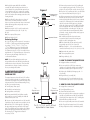
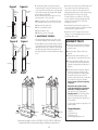
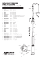
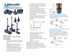
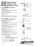
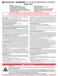
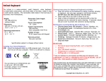
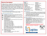
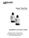
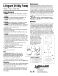
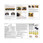
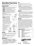
Ultraviolet Sterilizer Instructions
CAUTION: DO NOT
OPERATE BULB
OUTSIDE HOUSING.
EVEN BRIEF
EXPOSURE TO
ULTRAVIOLET
RADIATION CAN
CAUSE TEMPORARY
REDDENING
AND IRRITATION
OF EYES AND SKIN.
QL-15
QL-25
Congratulations on the purchase of your LIFEGARD
Ultraviolet Sterilizer. The radiation from the ultraviolet
light at 2537 angstroms provided inside the
LIFEGARD Ultraviolet Sterilizer exerts a lethal effect
on micro-organisms. This sterilizer, when installed
and used properly, is the most efficient and effective
method of disease control available.
A. WHERE TO INSTALL
The modular design of the Lifegard sterilizer allows it
to be easily added to an existing Lifegard filter system
(Figure A). In addition, the unit can also be installed
on the outlet side of most canister filters sold in the
aquarium industry today (Figure B). In every case, the
sterilizer is most effective in clear filtered water and
should be installed as the final stage in your filtration
system.
B. UNPACKING, ASSEMBLY, AND
INSTALLATION
NOTE: Instructions refer to item numbers of exploded
view parts break down PAGE 3.
1. Carefully unpack the quartz sleeve (#1), quartz bulb
(#2), ballast assembly (#3), cap (#4), and housing.
Make sure all packing material is removed from inside
housing.
2. Unscrew compression coupling from cap (#4),
remove rubber gasket (#5).
3. Insert quartz sleeve (#1) through cap (#4) leaving
the open end of the quartz sleeve protruding about
2” from top of cap.
QL-40
QL-80
QL-120
4. Slide gasket (#5) over the open end of quartz
sleeve until entire gasket is about 1/4” past end of
quartz sleeve. Gasket must remain entirely past open
end of quartz sleeve to achieve and maintain a proper
seal (Figure C).
NOTE: Failure to install quartz sleeve properly will
result in damage to bulb and ballast.
5. Screw small compression coupling onto cap (#4).
The compression coupling will push the quartz sleeve
into the proper position. Hand tighten only.
6. Carefully insert quartz sleeve into bottom receptacle
inside the center of the housing and tighten cap (#4).
Hand tighten only.
7. Repeat steps #2 - 6 for each chamber in the
commercial sterilizers (QL-80, QL-120, QL-160,
QL-240).
8. Attach ultraviolet sterilizer so it is “LAST” in
the filtration system (Figure A or Figure B). The
ultraviolet sterilizer is most effective in clear filtered
water. Make sure proper inlet and outlet ports are
utilized (Figure D for QL-15, Ql-25, QL-40; Figure E
for QL-80, QL-120, QL-160, QL-240).
9. Carefully match pins of male 4-pin connector [top
of quartz bulb (#2)] to female 4-pin connector (#6)
of ballast assembly (#3) and push fully into place.
10. Apply small amount of Lifegard Silicone lubricant
(R172036X) on rubber insert at the top of splash boot
to allow cord to slide easily. Gently pull cord above
splash boot (#7) and guide electrical connection until
it bottoms out into narrow neck of splash boot. Do not
pull fragile wires connecting the male 4-pin connector
to the quartz bulb (#2) as this will damage the bulb.
1
QL-160
QL-240
To
Aquarium
Quiet One
Pump
Mechanical Chemical
Filter
Filter
Heater
Module
Ultraviolet
Sterilizer
Figure A
From
Aquarium
To
Aquarium
Canister
Filter
Figure B
Ultraviolet
Sterilizer
11. Gently slide quartz bulb (#2) with ballast
assembly (#3) attached inside quartz sleeve until it
reaches bottom. Do not drop bulb into quartz sleeve.
Screw splash boot (#7) on to compression coupling
on cap (#4). This will prevent water that accidentally
spills on UV sterilizer from entering quartz sleeve and
wetting the bulb.
12. Place ballast (#3) where there is no chance of
water contact, a normal precaution for electrical
devices near water environments. Water contact with
ballast will damage ballast and possibly create an
electrical hazard.
13. Repeat steps #9 - #12 for each chamber in the
commercial sterilizers (QL-80, QL-120, QL-160,
QL-240.)
14. Turn on pump / filter system.
15. Plug in ballast(s), (#3)
Figure C
Compression
Coupling
Clear View
Port
Gasket
Cap
Quartz Sleeve
Reducing Bushings
Ql-15, QL-25 and QL-40 have option of connection to
3/4” MPT or 1” MPT using reducer bushings included
in package. 11/4”x 3/4”, 11/4”x 1”, 1 1/2”x 3/4” or
1 1/2”x 1”. Bushing of your choice should be glued
using a PVC/ABS compatible glue. All commercial
UV Sterilizers QL-80, QL-120, QL-160 and QL-240 are
supplied with a 2” Slip inlet/outlet port. Customer has
the option to glue the fitting of their choice for
a convenient installation.
NOTE: The beneficial nitrifying bacterial in your
biological filter will not be affected by the ultraviolet
radiation due to their sessile nature. These beneficial
bacteria adhere to all types of surfaces and are not
free to pass through the sterilizer.
Figure D
C. HOW TO REPLACE INTERNAL
PROTECTIVE SLEEVE AND 3/4”
OVERFLOW PIPE
The internal protective sleeve (#9) and 3/4” overflow
pipe (#10) must be replaced on a yearly basis in order
to maintain the integrity of the external housing.Yearly
replacement of these items will substantially prolong
the life of your sterilizer housing.
1. Turn off pump / filter system.
From
To
2. Shut off inlet and outlet valves.
Aquarium
Aquarium
3. Unplug ballast assembly (#3)
INLET
OUTLET
4. Pull out quartz bulb (#2) and ballast assembly
(#3) together as one unit. Carefully place bulb and
ballast assembly to the side.
5. Unscrew cap (#4) with quartz sleeve (#1) attached.
Carefully place cap and quartz sleeve assembly to the side.
6. Remove the 3/4” overflow pipe (#10) by pulling
The QL-15, QL-25, and QL-40 must
the pipe straight up using your hands and/or small
be plumbed as shown above.
pliers. The overflow pipe is not glued in place. Pulling
upward will dislodge it from the stub at the base of
the housing (Fig. F). Wiggle back and forth if
necessary to loosen.
2
7. Remove the protective sleeve (#9) by pulling the
sleeve straight up using your hands. The sleeve is not
glued in place and will slide out of the housing (Fig. G).
8. Place new 3/4” overflow pipe (#10) over stub at the
base of the unit. Push firmly into place (Fig. H).
9. Slide new protective sleeve (#9) into housing with
stabilizer clip (#9) at top of sleeve. Push the sleeve
into the housing with slotted side of sleeve positioned
around 3/4” overflow pipe (#10) inside the stabilizer
clip (#9) so that the overflow pipe rests along the
inside edge of the housing (Fig. J). NOTE: All overflow
pipes are equipped with a 1/8” air bleed tube which
must be positioned so that the tip of 1/8” tube is at
top of chamber when mounted horizontally. When
positioned correctly, the tube will be exactly opposite
horizontal stand. (Fig. J).
11. Carefully insert quartz sleeve into bottom
receptacle inside the center of the housing and
tighten cap (#4). Hand tighten only.
12. Place quartz bulb (#2) into quartz sleeve (#1)
by repeating steps #11- #12 in section (B).
13. Repeat steps #3 - 12 for each chamber in the
commercial sterilizers (QL-80, QL-120, QL-160, QL-240).
14. Open inlet and outlet valves.
15. Turn on pump/filter system.
16. Plug in ballast(s), (#3)
D. HOW TO CHANGE THE QUARTZ BULB
1. Unplug the ballast assembly (#3).
2. Unscrew splash boot (#7) from compression
coupling on cap (#4) and carefully remove bulb (#2)
and ballast assembly (#3) from quartz sleeve (#1).
3. Replace the old bulb by following steps #9 - 12
of section (B).
4. Plug in ballast(s), assembly (#3).
5. Repeat steps #1-5 for each chamber in the commercial sterilizers (QL-80, QL-120, QL-160, QL-240).
E. HOW TO CLEAN THE QUARTZ SLEEVE
1. Unplug ballast assembly (#3).
2. Turn off pump/filter system.
3. Shut off inlet and outlet valves.
4. Unscrew splash boot from compression coupling on
cap (#4) and carefully remove bulb (#2) and ballast
assembly (#3) from quartz sleeve (#1). Carefully place
bulb and ballast assembly to the side.
5. Unscrew cap (#4) with quartz sleeve (#1) attached.
6. Lift off cap (#4) and quartz sleeve (#1) assembly.
7. Wipe off quartz sleeve (#1) with rubbing alcohol.
Figure F
Figure G
Protective
Sleeve
3/4”
Overflow
Pipe
Housing
Housing
8. Carefully insert quartz sleeve (#1) into bottom
receptacle inside the center of the housing and screw
on cap (#4). Make sure all threads on cap and housing
are free of dirt. Lubricate “O” ring (#8) with LIfegard
silicone lubricant. (R172036X)
9. Place quartz bulb (#2) into quartz sleeve (#1) by
repeating steps #11-12 in section (B).
10. Repeat steps #4-9 for each chamber in the commercial sterilizers (QL-80, QL-120, QL-160, QL-240).
11. Open inlet and outlet valves.
12. Turn on pump/filter system.
13. Plug in ballast(s), (#3).
14. Make sure system is water tight.
F. MAINTENANCE SCHEDULE
Figure H
Figure I
3/4”
Overflow
Pipe
Stabilizer
Clip
Protective
Sleeve
All of the following maintenance procedures can be
conveniently scheduled at the same time every year.
1. Quartz Bulb (#2) The quartz bulb must be replaced
on a yearly basis. The characteristic visible blue glow
emitted by the bulb is not an indication of the amount
of invisible ultraviolet radiation being produced. The
blue glow will still be seen when the ultraviolet output
is zero.
2. Protective Sleeve (#9) and 3/4” Overflow Pipe (#10)
The protective sleeve and overflow pipe must be
replaced on a yearly basis. This replacement will
substantially prolong the life of your sterilizer housing.
3. “O” Ring (#8) The “O” ring on the cap (#4)
should be replaced on a yearly basis. The “O” ring
must be cleaned of any debris and lubricated with
Lifegard silicone lubricant (R172036X) before
inserting into clear cap.
4. Gasket (#5) The gasket must be replaced on a
yearly basis. Failure to replace the gasket may result in
a water leak into the quartz sleeve (#1).
5. Quartz Sleeve (#7) The quartz sleeve must be
cleaned once a year with rubbing alcohol to remove
any build up of dirt or slime.
WARRANTY POLICY
u Warranty period starts from date of purchase and must be validated with copy of original purchase receipt.
u Warranty requests by phone will not be honored.
u Warranty items returned without copy of original purchase receipt will not be honored.
u Products purchased from EBay, Craig’s List, Housing
etc. cannot be honored for warranty unless returned by original purchaser with proof of purchase.
Housing
u All items must first be returned to Lifegard
Aquatics for inspection, evaluation, and processing to determine if product qualifies for warranty replacement or repair. No
warranty (repair, replacement, or credit) will be issued prior to inspection of product. Please contact us first for warranty assistance.
Many times the product can be repaired without the cost and time involved in sending it back to us.
If absolutely necessary, return product freight prepaid to the following address for warranty evaluation and processing.
One year warranty from date of purchase on all UV sterilizers.
60 day warranty from date of purchase on all ultraviolet bulbs.
Figure E
Plug
Plug
Lifegard Aquatics
Outlet
Inlet
Plug
Inlet
Plug
Outlet
Commercial ultraviolet sterilizers (QL-80, QL-120, QL-160, QL-240) can be
plumbed two different ways depending on installation requirements.
3
Cerritos, CA
Tel (562)404-4129
Fax (562)404-4159
Email: [email protected]
ULTRAVIOLET STERILIZER
PARTS BREAK DOWN
7
QL-15, QL-25, QL-40, QL-80, QL-120, QL-160, QL-240
ITEM MODEL PART # 1 QL-15 R175060 1A QL-25 R175233 1B QL-40 to QL-240 R175234 2 QL-15 R175229DP 2A QL-25 R175230DP 2B QL-40 to QL-240 R175231DP 3 QL-15/25/40
R175267
3A QL-15/25/40
R175278
4 QL-15 to QL-240 R175109 5 QL-15 to QL-240 R175022X 6 QL-15 to QL-240 R175232 7 QL-15 to QL-240 R175235 8 QL-15 to QL-240 220001 9 QL-15 R177333 9A QL-25 R177334 9B QL-40 R177335 9C QL-80 to QL-240 R177336 10 QL-15 R177338 10A QL-25 R177340 10B QL-40 R177342 10C QL-80 to QL-240 R177344 11 QL-15, QL-25, QL-40 R174000
11A QL-15, QL-25, QL-40 R174001
11B QL-15, QL-25, QL-40 R174002
11C QL-15, QL-25, QL-40 R174003
12 QL-15, QL-25, QL-40 R270313
12A QL-15, QL-25, QL-40 R270484
6
DESCRIPTION
Quartz sleeve
Quartz sleeve
Quartz sleeve
Quartz bulb
Quartz bulb
Quartz bulb
15/25/40Watt ballast for QL-40, 80, 120, 160, 240
15/25/40Watt 230V, 50Hz, ballast for QL-40, 80,
120, 160, 240
Cap w/coupling
Gasket
Female 4 pin connector
Splash boot
“O” ring
Protective sleeve
Protective sleeve
Protective sleeve
Protective sleeve
3/4” overflow pipe
3/4” overflow pipe
3/4” overflow pipe
3/4” overflow pipe
1 1/4” x 3/4” Lifegard Reducer Bushing
1 1/4” x 1” Lifegard Reducer Bushing
1 1/2” x 3/4” Lifegard Reducer Bushing
1 1/2” x 1” Lifegard Reducer Bushing
3/4” Close Nipple
1” Close Nipple
Male 4 pin
connector
2
5
4
8
1
11
11A
11B
11C
12
12A
10
Stabilizer Clip
9
Top View
Air Bleed Tube
Protective
Sleeve
Housing
3/4” Overflow
Pipe
Stabilizer Clip
Horizontal
Stand Kit
Housing
Figure J
Email: [email protected] Web Site: www.lifegardaquatics.com
4