1
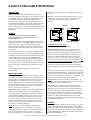
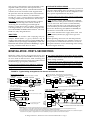
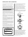
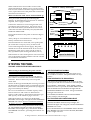
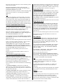
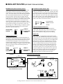
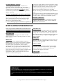
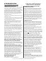
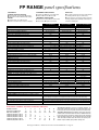
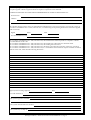
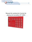
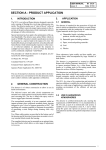
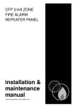
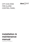
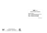
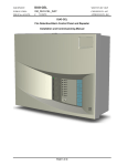
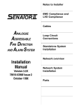
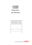
FP Range 2-14 Zone Fire Alarm Control Panels
INSTALLATION INSTRUCTIONS
PLEASE READ THESE INSTRUCTIONS CAREFULLY BEFORE
INSTALLING AND/OR MAINTAINING THIS EQUIPMENT
These instructions are general and cannot be considered to cover every aspect of fire alarm installation.
We recommend you read BS 5839: Pt 1: 1988 "Fire Detection and Alarm Systems for Buildings" (available
at your local reference library or from the BSI).
No responsibility can be accepted by the manufacturers or distributors of this range of fire panels for any
misinterpretation of an instruction or guidance note or for the compliance of the system as a whole.
Contact the Fire Officer concerned with the property at an early stage in case he has any special
requirements. We strongly recommend that a suitably qualified and competent person is consulted in
connection with the design of the Fire Alarm system.
The manufacturers policy is one of continuous improvement and we reserve the right to make changes
to product specifications at our discretion and without prior notice. E&OE.
IMPORTANT NOTES
1.
This equipment must only be installed and maintained by a suitably skilled or technically
competent person.
2. This equipment is a piece of class 1 equipment and MUST BE EARTHED.
3. To meet the requirements of BS 5839 Part 1 1988 Amendment N° 1 (Effective Jan. 1991) "Fire Detection
and Alarm Systems for Buildings", manual call points must still operate when any detector(s) are
removed from their bases. This must be done whether or not the detectors have locking or shorting
devices. To comply, either the manual call points must be wired before the detectors, or detector bases
with diodes fitted must be used to ensure continuity when detectors and call points are installed in mixed
order. If diodes are incorporated then the FP Range of panels will not show a fault when a detector is
removed unless an EMU (Electronic Monitoring Unit - BF378) or MINIMU (MiniatureElectronic
Monitoring Unit - BF378M) is substituted for the End of Line Resistor (see page 3).
4. If you connect the battery leads in reverse you will blow the battery fuse and you RISK DAMAGING
THE PANEL. The fault is factory detectable and you WILL BE CHARGED FOR THE REPAIR.
5.
If the Battery/Power Supply fault light comes on whilst the Green Mains On light is lit then it
usually means that the battery is either discharged or faulty (see page 9 inside for details).
Important Notes
Page 1
Testing The Panel
Page 5
Guide to System Design
Page 2
Ancillary Facilities
Page 7
Installation - First Fix
Page 3
Troubleshooting
Page 9
Installation - Second Fix
Page 4
Panel Specification
Page 10
FP Range Installation / Maintenance Instructions DFU0384000 Rev 4 • Page 1
■ GUIDE TO FIRE ALARM SYSTEM DESIGN
CONTROL PANEL
The fire panel must be sited internally, in an area
where it is readily accessible by staff on duty and the
fire brigade. The area should be clean and dry and
you should take into account any likelihood of
tampering or vandalism. The ambient light and
sound levels should allow the status of the indicators
to be clearly seen and the internal sounder to be
heard. Full details can be found in BS 5839: Pt1: 1988:
Section 15.3 "Fire Detection and Alarm Systems for
Buildings".
any other form of switch used to trigger the detector
circuits.
N.B. It is possible to disable the short circuit = fault
condition for each zone so that a short circuit will
cause a fire condition (see page 7 for further
details).
FIGURE 1
Call point resistor
Loop
In/out
Call point resistor
NC
SOUNDERS
C
ALL SOUNDERS MUST BE POLARISED.
UNPOLARISED SOUNDERS WILL SHOW A
SOUNDER FAULT.
The most common sounders are bells and electronic
sounders. Motorised sirens MUST NOT be used on these
panels . The same type of sounder must be used
throughout the building and it must be distinctive so
that the sound associated with a fire alarm is easily
recognised.
The minimum sound level is 65 dB or 5 dB above any
background noise likely to persist for longer than 30
seconds. The fire alarm must be audible in every part
of the building. For sleeping accommodation the
sound level should be 75 dB at the bedhead if sleeping people with normal hearing are to be wakened.
Two sounder circuits are provided. Sounders should
be wired in approximately equal numbers on each
circuit.
One sounder should be adjacent or near to the
control panel.
MANUAL CALL POINTS
Manual Call Points should be sited on all exit routes
especially on landings and staircases and by final exit
doors, with a maximum distance from any place in
the building to a Call Point of 30 metres, (less distance in high risk areas). They should ideally be sited
1.4 metres above the floor and in a conspicuous and
easily reached position. Any number of call points
can be connected on each zone.
Important. Many call points are now supplied with a
resistor already fitted. This can be determined by
measuring with a good quality Ohmmeter. The call
point should normally measure open circuit, and
between 470 and 680 ohms when activated. If the
call points are not of this type then a series resistor
must be connected in series with the call point in
order to ensure that an alarm condition will occur.
See figure 1 for fitting diagram.
Note: Resistors are not included with the panel
instruction pack but are available from electronic
component suppliers. Failure to include this resistor
will cause the panel to show a short circuit fault
when the call point is operated. This also applies to
NC
C
Call point
switch
NO
Normal Position
NO
Loop
In/out
Activated Position
SMOKE AND HEAT DETECTORS
See page 10 for maximum amount.
Smoke Detectors: There are two types of smoke
detector, Ionisation and Optical. Ionisation are
generally quickest at detecting a clean burning fire.
Optical are quickest at detecting smouldering fires.
Neither one is better than the other in all circumstances. Some Fire Authorities will only allow one
kind and you should check with the Fire Officer. Do
not site smoke detectors in draughts. Siting of the
detectors depends on many factors and BS5839: Pt1:
1988 "Fire Detection and Alarm Systems for Buildings" should be consulted for full details of spacing,
etc.
Dirt, dust, smoke, steam, water vapour and condensation will affect the detectors, causing false alarms and
the need for frequent cleaning. Under these conditions,
the use of heat detectors should be considered (see
below). If in doubt, consult the Fire Officer.
Note: Building work causes adverse conditions. If
possible, remove all detectors from site until work is
completed to avoid contamination.
Heat Detectors: These are used in places where
smoke detectors are not practical, such as kitchens
and boiler rooms. There are two kinds, Fixed Temperature and Rate of Rise. Fixed Temperature Heat
Detectors are used where sudden rises in temperature which would cause alarms are common, such as
in kitchens. Rate of Rise Heat Detectors are used
elsewhere as they generally respond faster than Fixed
Temperature Detectors.
BATTERIES
For the emergency stand-by power supply, two good
quality 12V sealed lead acid batteries (connected in
series) should be used. They should be of a type that
have at least four years life under normal conditions.
Consult BS5839: Pt1: 1988 "Fire Detection and Alarm
Systems for Buildings".
FP Range Installation / Maintenance Instructions DFU0384000 Rev 4 • Page 2
The capacity of the batteries used will depend on the
required stand-by time (See 'Panel Specification',
page 10, for stand-by times). Note that the number of
sounders, detectors and other loads supplied from
the panel also alter the stand-by time of the batteries.
NOTES ON THE OVERALL DESIGN
For battery connection details, see 'Installation Second Fix', page 5. Always dispose of used batteries
according to the battery manufacturers instructions.
The Fire Officer has the right to refuse to grant a fire
certificate until he is satisfied.
If you are suitably qualified decide on the position of
all parts and mark the plans accordingly. Get the Fire
Officer to check the plans to ensure compliance with
any special requirements he may have.
Note: To fully comply with BS5839 Part 1 Manual
Call points must still operate when any of the Detectors are removed. This can be accommodated by
wiring Call Points first or by using detector bases
with continuity diodes fitted and substituting an
Electronic Monitoring Unit (BF378 or BF378M) for
the detector circuit End of Line Resistor.
Important: The FP Range of panels features a sophisticated battery monitoring circuit which, instead of
monitoring the current being passed through the
batteries, actually detects their condition. Consequently,
a discharged battery or one with deteriorating cells will
show a BATTERY/POWER SUPPLY FAULT. Test with
brand new, fully charged batteries.
Note: Some manufacturers supply bases with integral continuity diodes (see page 10 for type and
quantity).
CABLE TYPES
Sounders must be wired in cable complying with, for
example, BS6207 (MICC or ‘pyro’). Detectors may be
wired in cable complying with, for example, BS6004 (PVC)
or BS6207. Ensure you comply with BS5839 Pt1: 1988 "Fire
Detection and Alarm Systems for Buildings" regarding siting, installation and choice of cables.
When planning cable runs note that the panel has
provision for terminating two sounder circuits. It is
not possible to terminate more than two circuits at
the panel and have correct monitoring of the wiring
(refer to figure 2 below).
■ INSTALLATION - FIRST & SECOND FIXES
test voltage will destroy all of these devices totally.
Install the cables and fit call point back boxes and
detector bases where possible. N.B. If continuity diodes
are to be used in detector bases, mark incoming and
outgoing cables to aid correct connection. Cables should
be tested using a good quality multimeter.
If fitted, smoke detector bases must be ‘linked out’ to
check wiring continuity.
Do not leave any part of the fire alarm system where
it may become dusty or damp (due to any building
work such as plastering, painting, carpet fitting,etc)
as this will result in possible malfunctions, including
false alarms.
Do not use an insulation tester (Megger) with any
detectors, sounders, continuity diodes or control
equipment of any kind connected as the 500 volt
FIGURE 2 : Typical wiring arrangements for detector and sounder circuits.
CALL POINT
DETECTOR
CPR
CPR
+
NEVER SPUR LOOP THEN NOT
MONITORED
EOLR = End of Line Resistor (6800Ω)
CPR = Call Point Resistor
(470-680Ω - Usually supplied with call point)
TYPICAL SOUNDER CIRCUIT
Note - Sounders must be polarised
SOUNDER TERMINALS
DETECTOR
DO NOT SPUR
56+
+
EOLR= end of line resistor (6k8Ω)
+
SOUNDERS
78+
+
PANEL ZONE
TERMINALS
CALL POINT
-
+
-
+
ELECTRONIC MONITOR UNIT
ELECTRONIC MONITOR UNIT PANEL MODULE
*THREE WIRE SYSTEM Combined detector and sounder loops using commomn negative conductor,
including mixed order detector bases and call points
DETECTOR
DETECTOR
CALL POINT
CALL POINT
+
BF378 or
BF378M
CPR
+
EOLR
+
+
+
Do not make off more than
2 circuits in the panel
BF378 or
BF378M
PANEL ZONE
TERMINALS
PANEL ZONE
TERMINALS
ZONE LOOP CIRCUIT - With mixed order call points and detectors
(Detector bases fitted with continuity diodes, and negative conection
linked out)
DETECTOR
DETECTOR
CALL POINT
CALL POINT
+
CPR
CPR
-
PANEL
SOUNDER
TERMINALS
PANEL ZONE
TERMINALS
TYPICAL ZONE LOOP CIRCUIT
Call points wired before detectors - detector base diodes not needed
+
+
+
+
6or 8 +
SOUNDERS
ELECTRONIC MONITOR UNIT
5or 7 -
ELECTRONIC MONITOR UNIT PANEL MODULE
*IMPORTANT Some cautionary points about the three wire system illustrated.
i. This configuration is used to utilise existing wiring when refurbishing an existing system. New installations are not usually planned in this way.
ii. The system must be connected so that if any head is removed then all the sounders will still operate.
iii. Since the common wire carries all the current for the sounders and the detectors it should be of low impedance and connected to the sounder circuit negative
Check that when any detector is triggered that it will not be inadvertantly reset by the sounder current in an alarm condition.
FP Range Installation / Maintenance Instructions DFU0384000 Rev 4 • Page 3
■ INSTALLATION - FIRST & SECOND FIXES
Take the control panel out of its box and undo the
two screws at the top using the key provided in the
accessory pack.
All external wiring brought into the panel should be
adequately insulated with PVC, PTFE, Neoprene or
other fire resistant /retardent material.
Hinge the lid down 180° and remove the earth
connection. Locate the connector plug (PL7) on the
main printed circuit board. Grasp the wires to the
plug firmly and pull the connector off the board.
Disconnect plugs of PL4 on any zone boards fitted.
Hinge the lid back 90° and lift the front panel off.
DO NOT connect the detector wiring into the
terminal block in the panel until you have tested the
panel (see page 5). With all power removed from the
panel, fit the sounders, call points, and detectors.
Before fitting the last devices on the sounder and
detector circuits remove the End of Line Resistors
from the terminal blocks and fit across the last device
on each circuit.
The front panel may be removed from site until work
is completed, if it is likely to get damaged.
Fix the base of the fire panel securely to the wall
using the mounting holes provided (see 'A', figure 3).
The mounting holes are suitable for use with No. 8
round head or countersunk woodscrews. Assess the
condition and construction of the wall and use a
suitable screw fixing. Any dust created during the
fixing process must be kept out of the fire panel, and
great care must be taken not to damage any wiring or
components.
If continuity diodes are to be used in detector bases then
they must be fitted and wired in the correct orientation
as shown in the Detector base details (see Figure 4).
FIGURE 4
Diode only passes current when this
end more positive than the other
Electrical Symbol
All mains wiring should be provided in accordance
with the current edition of the IEE Wiring Regs, 16th.
Ed. (BS 7671, 1993) or in accordance with the relevant
national wiring rules.
The general requirement for the mains supply to this
equipment is fixed wiring, using three core cable, not
less than 0.75mm2 or a suitable three conductor
system, fed from an isolating switch fuse spur, fused
at 3A. This should be marked "FIRE ALARM: DO
NOT SWITCH OFF" and should be secure from
unauthorised operation.
The mains connection is made inside the fire panel to
the fused mains terminal block only. Connection
must not be made to the mains supply using a plug
and socket. The mains supply should be exclusive to
the fire panel. (Full details can be found in BS5839:
Pt1: 1988 section 15.3. "Fire Detection and Alarm
Systems for Buildings").
The wiring of the panel should be carefully planned
before starting the job. Always ensure that if a
knockout is removed, that the hole is filled with a
good quality cable gland. Plan and route all of the
wiring as indicated in Figure 3 by the dotted lines.
FIGURE 3
B
A
B
B
B
B
B
B
B
B
B
-
Light coloured band
Actual part
Diode Detail
Continuity Diode
(Shorted out when head in place)
+IN
+OUT
To next Detector,
Call Point, and through
to End of line Device
-OUT
-IN
Link or common
connection
Detector Base Detail
(with head in place)
Continuity Diode
(Passes current when head removed)
+IN
+OUT
-IN
-OUT
Detector Base Detail
(with head removed)
A
B
A
+
A
B
A = mounting holes, B = knock-outs
The diode must be connected so that it is shorted out by
the internal connections of the head when the head is in
place, and provide a path for the current in the loop
when the head is removed. Incorrect fitting will not
cause damage but will cause malfunctions of the
system. (See troubleshooting guide on page 9). The End
of Line Resistor must be replaced by an Electronic
Monitoring Unit (BF378 or BF378M) and its associated
Panel Module. See BF378 or BF378M instructions and
wiring arrangements on page 3 (figure 2).
FP Range Installation / Maintenance Instructions DFU0384000 Rev 4 • Page 4
Connect the batteries in series using the link wire
provided as shown in Figure 5. Always be sure of
the connections before you make them as incorrect
connection will blow the battery fuse (F5) and MAY
DAMAGE THE PANEL.
Postion the batteries in the panel as shown in Figure
6 (right).
Always dispose of used batteries according to the
battery manufacturers instructions.
+
–
12V battery
12V battery
–
BLACK
WIRE
RED
WIRE
BLACK
WIRE
Connections to
the fire panel
RED
WIRE
+
12V battery
–
–
Next, power the system up by connecting the
batteries. To determine the type and size of batteries
required, refer to pages 2 and 10.
Use the shorting link in
the accessory pack
12V battery
+
Make sure that the earth wire is connected back up.
FIGURE 5 : Battery Connection
+
Make off the detector and sounder circuits at the
panel terminal block. When you are sure all connections are firm with no insulation trapped and no bare
wires, replace the front of the panel and re-attach the
relevant loom connectors.
FIGURE 6
Once the batteries are connected, close up the panel
(be careful not to trap any wires), fit the two lid
screws and energize the mains supply. The panel
should now be in the Normal mode. If not see troubleshooting guide page 9. Now test the system is
fully operational ( See 'Testing The Panel', below).
If the number of zones of the panel is to be increased,
refer to the leaflet supplied with the relevant zone kit
for installation instructions.
space for batteries
■ TESTING THE PANEL
THE PANEL CAN BE TESTED BEFORE CONNECTING UP
When testing or maintaining the panel with the
panel lid open, always - where possible - isolate the
mains and disconnect the batteries.
If testing before installation make sure the End of
Line resistors are fitted in the sounder and detector
terminals. Do not connect any wires except the
mains feed.
Fit PL7 on the large main PCB (the red wire goes to the
left hand side as marked on the circuit board) and any
PL4's on the zone PCBs on the panel front (see figure 7,
page 7 for PCB layout details).
Put two 12 Volt batteries of suitable capacity in the
bottom of the box and connect as illustrated in
figures 5 and 6 (above). Information on battery type
and capacity can be found on pages 2 and 10.
When the batteries are connected, the MAINS/
BATTERY FAULT light will light and the WARNING
BEEPER will sound. Incorrect connection will blow
the battery fuse (F1) and MAY DAMAGE THE PANEL
Connect the mains wiring and turn the mains supply
on. The MAINS ON light will light, the MAINS/
BATTERY FAULT light will go out and the WARNING BEEPER will silence, providing the batteries are
not flat.
WITH THE KEYSWITCH AT NORMAL
The MAINS ON light is lit. No other lights are lit.
No sounders are active. The push buttons are inoperative.
TURN THE KEYSWITCH TO ARM CONTROLS.
This allows the push buttons to be used by an authorised person but does not otherwise affect the panel.
Press RESET / RESOUND / TEST ZONE LAMPS.
Whilst the button is pressed the ZONE FIRE LIGHTS
and the ZONE FAULT LIGHTS will light and the
WARNING BEEPER will sound. The green MAINS
ON light will remain lit.
The MAINS/BATTERY FAULT and SOUNDER
FAULT lamps will NOT light.
TEST THE POWER SUPPLY MONITORING CIRCUIT
Switch off the Mains. After several seconds the
MAINS/BATTERY FAULT lamp will light, the
MAINS ON light will extinguish, and the WARNING
BEEPER will sound.
Press SILENCE FAULT SOUNDERS and the WARNING BEEPER will silence but the MAINS/BATTERY
FAULT light will be lit.
FP Range Installation / Maintenance Instructions DFU0384000 Rev 4 • Page 5
Reconnect the mains and after a short time the panel
will revert to normal.
Disconnect the Battery. After a short time the
MAINS/BATTERY FAULT light will light and the
WARNING BEEPER will sound.
Reconnect the battery and after a short time the panel
will revert to normal (i.e. only the green MAINS
lights on).
Note
1) This test should be carried out with a set of new
and fully charged batteries – deteriorated cells will
show a fault even when connected and charged up.
2) If good but completely discharged cells are used
the MAINS/BATTERY FAULT light will stay on for
several minutes until the battery obtains sufficient charge.
TEST THE SOUNDER MONITORING CIRCUIT(S)
DO NOT carry out this test with any red FIRE lights
lit as the sounder fuse(s) F2, 3 could blow. Make sure
the End of Line resistor is connected across the
sounder circuits on terminals (5&6, 7&8).
Short the sounder terminals 5 & 6 and keep them
shorted. The SOUNDER FAULT light will light and
the WARNING BEEPER will sound.
Press SILENCE FAULT SOUNDERS and the WARNING BEEPER will silence but the SOUNDER FAULT
light will stay on.
Remove the short and the panel will revert to normal.
Open circuit the sounder terminals 5 & 6 by removing one leg of the end of line resistor. The
SOUNDER FAULT light will light and the WARNING BEEPER will sound. Press SILENCE FAULT
SOUNDERS and the WARNING BEEPER will silence
but the SOUNDER FAULT light will stay on.
partial short when they are triggered, but manual call
points need to have 470 to 680Ω resistors connected
in series to give a partial short. (Check - Resistor may
be incorporated in the Call Point, see page 2)
OPEN CIRCUIT FAULTS
Open circuit the detector terminals 9 & 10 by removing one wire of the EOLD. The ZONE 1 FAULT light
will light and the WARNING BEEPER will sound.
Inside the panel, the ZONE ONE OPEN CIRCUIT
fault light will light. Press SILENCE FAULT
SOUNDERS and the WARNING BEEPER will silence
but the lights will stay on.
Remake the circuit and the panel will revert to normal.
SHORT CIRCUIT FAULTS
Short circuit the detector terminals 9 & 10 and keep
them shorted. The ZONE 1 FAULT light will light
and the WARNING BEEPER will sound. Inside the
panel, the ZONE ONE SHORT CIRCUIT fault light
will light. Press SILENCE FAULT SOUNDERS and
the WARNING BEEPER will silence but the lights
will stay on.
Remove the short and the panel will revert to normal.
Repeat the tests for the other detector circuits via
terminals 11 & 12.
FIRE CONDITION
Simulate a Fire condition by connecting and activating a Manual Call point or by fitting a 470 to 680 Ω
across terminals 9 & 10. The sounder output relay
will operate, the ZONE 1 FIRE light will flash – the
panel has gone into alarm.
Press SILENCE ALARM SOUNDERS. The sounder
output relay will click back and the ZONE 1 FIRE
light will light steadily. The WARNING BEEPER
will now sound.
Remake the circuit and the panel will revert to
normal.
Press RESET / RESOUND / TEST ZONE LAMPS
and the panel will go back into alarm.
Repeat the tests for the other sounder circuit via
terminals 7 & 8.
Remove the call point resistor.
TEST THE DETECTOR MONITORING CIRCUITS
Make sure an End of Line device is connected across
each pair of detector terminals ( 9 & 10, 11 & 12, etc.).
The EOLD would either be a 6.8kΩ Resistor or
Electronic Monitoring Unit (EMU) and associated
Panel Module, depending on the installation.
Four conditions can exist on the detector monitoring
circuits.
1. Normal condition. Current flows round the
detector loop via the end of line resistor to monitor
the wiring. Detectors and call points are connected in
parallel across the line.
Press SILENCE ALARM SOUNDERS then RESET /
RESOUND / TEST ZONE LAMPS and the panel will
revert to normal. Repeat the test for the other detector circuits via the other zone terminals.
Note
1) Pressing RESET/RESOUND/TEST ZONE
LAMPS when in the fire condition (i.e. red lights
flashing) has no effect.
2) When the fire alarm is silenced, i.e. steady red
lights, the fault buzzer will be on and cannot be
silenced.
3) Resetting the system from the silenced state with the
fire condition still existing will RESOUND the alarm.
2. Open Circuit Fault. The wiring is broken at some
point and the monitoring current cannot flow.
FINALLY
3. Short Circuit Fault. A dead short exists at some
point and too much monitoring current flows.
The output relays will switch over to operate the sounders.
4. Fire condition. A partial short exists and the
monitoring current increases but not enough to show
a short circuit fault. Most smoke detectors make a
Press EVACUATE.
If you wish these tests can be carried out with a
sounder and smoke detector and a call point from
each circuit connected into each pair of terminals and
the end of line resistors fitted to them.
FP Range Installation / Maintenance Instructions DFU0384000 Rev 4 • Page 6
■ ANCILLARY FACILITIES (SEE FIGURE 7 FOR LINK POSITIONS)
ENGINEERS TEST (NON-LATCH TEST) FACILITY
TO REVERT TO SHORT CIRCUIT = FIRE
This range of panels has a non-latching test facility
which allows manual call points and automatic
smoke detectors to be tested and to reset automatically. To set this facility move the link plug marked
PL1 on the main PCB from the lower to the upper
position and the adjacent LED will light and the
warning buzzer will sound and cannot be silenced.
When an alarm condition is caused the alarm sounders will operate for about half a second and will
silence for three seconds before resounding. This
will continue until the cause of the alarm is removed
by the smoke clearing from a detector or the call
point being reset. When testing is complete, replace
the link in the lower position (A non functional
position to prevent link loss).
Next to the Open and Short Circuit Fault indicating
LEDs for each Zone is a link wire. Cutting this link
overrides the short circuit fault monitoring circuit for
that zone and allows the panel to be used on installations which do not have Call Point Resistors fitted.
Note: This facility is for older installations only as it
does not comply with the latest British Standards. If in
doubt, seek advice from the fire officer.
ENG
LINK IN LOWER
POSITION
ENG
LAMP LIT –
LINK IN UPPER
POSITION
Cut so short circuit
Fault
leds
condition is Fire and
not Fault
AUXILIARY EXPANSION PLUG (PL10)
This plug offers facilities for driving Repeater
Panels, Fire and Fault relays, and a "Class Change"
input. These facilities require various ancillary
devices to be added to the panel. (not included).
AUX 24V +VE
ZONE ISOLATION FACILITY
Each Detector Zone can be isolated individually if
required by moving the link plug from the lower to
the upper position. The adjacent LED and relevant
zone fault LED will light to show that the zone is
isolated. The warning buzzer will sound and can be
silenced. When testing is complete, replace the link in
the lower position (A non functional position to
prevent link loss).
ISOLATE
LINK IN
LOWER
POSITION
LAMP LIT –
LINK IN UPPER
POSITION
FIGURE 7
This output is a regulated but unmonitored output
fused at 1A (F4), available from terminal 1 in the base.
With link PL3 on the main PCB (adjacent relay) linked
in position furthest from the F4 fuse on the Main PCB
this output is continuous. If linked near to the fuse
then the output is present when the panel is normal
but is switched off when the relay is activated. This
facility can be used to provide a fail-safe output via
Aux 24v, that "switches off" when the sounders are
activated or if the power to the panel fails. Note: any
load provided by this output increases the quiescent
drain on the panels supply which in turn affects the
stand-by time of the system. It is not intended to
supply door release systems (see next page).
Circuit board Layout and features
PL3
(not normally used)
TWO ZONE MAIN BOARD
PL4 Zone
connection plug
Left zone
Right zone
SYSTEM EXPANSION
KEYSWITCH
ZONE EXPANSION
Cut to change to
short circuit = fire
for relevant zone
To next
zone card
Fault lights
PL10
X
PL11
PL2 PL1
PL8
PL9
PL2
PL4
+
PL1
BP1
CUT SC = FIRE
Isolation link to plugs & lights
TWO ZONE EXPANSION BOARD
SOUNDER FUSES
PL3
F3
F2
VR1
F4
F1
RLY1
PL7
RED
FP Range Installation / Maintenance Instructions DFU0384000 Rev 4 • Page 7
BATT.
FUSE DO NOT
AUX 24V
ADJUST
OUTPUT FUSE
VOLTAGE FREE RELAY CONTACTS
These single pole relay outputs available via 2
(normally closed), 3 (common), and 4 (normally
open) in the base connections change over when the
sounders are activated. They must not be used to
switch mains potentials, the contacts being rated at
30vD.C. and 1.0A.
NOTE ABOUT HOLDING MAGNETS (MAGNETIC DOOR RETAINERS)
BS5839 Pt1: 1988: "Fire Detection and Alarm
Systems for Buildings" states that devices which
draw current in the non Fire state and thus reduce
the battery stand-by time must not be fitted. We
therefore recommend that either:1) 24 Volt holding magnets should use a separate 24
Volt power supply under control of the panel. Ideally
the separate supply should be of a "Hold off" type that
requires very little control current from the panel.
2) 240 Volt holding magnets should be used, in
which case a separate mains power switching
24 Volt coil relay, powered from the panel, should be
used.
Special polarised relays (Part N°BF376) and PSUs (Part
N° BF377) are available for connecting to the sounder
circuits to allow control of Door Release systems.
REPEATER CONNECTIONS
Repeaters are driven from a transmitter board that
requires connection to PL10 on the main PCB and
and PL3 on the zone PCB.
■ FIRE ALARM SYSTEM INSPECTION
This is a requirement of BS5839 Pt 1: 1988 "Fire Detection
and Alarm Systems for Buildings" and should be carried
out by person(s) responsible for supervising the system.
DAILY INSPECTION
Check the MAINS ON light is lit. Check no other
lights are lit or sounders operating. Notify any faults
to the installer.
WEEKLY TEST
Turn the Keyswitch to ARM CONTROLS and press
RESET. Check the zone light shows and that the WARNING BEEPER sounds. Operate a call point or sensor to
test the fire alarm. Check that the alarm sounders
operate. Reset the fire alarm by pressing SILENCE and
then RESET (Two people may be needed for this test).
Each week test a different call point, so that all call
points and sensors are tested in rotation. A building plan
detailing the call point / sensor location is recommended. Check all call points and sensors and verify
that none is obstructed in any way.
QUARTERLY TEST
Check all previous Log Book entries and verify that
remedial action has been taken. Visually inspect the
battery and its connections. Test the fire alarm as in
the weekly test above. Remove the mains supply and
check that the battery is capable of supplying the
alarm sounders.
ANNUAL TEST
As for the weekly and quarterly tests but check every
detector, call point, sounder and all auxiliary equipment for correct operation.
EVERY 2 -3 YEARS
Clean the smoke detectors to ensure correct operation and freedom from false alarms. Special equipment is required for cleaning smoke detectors.
Consult your supplier if in doubt.
EVERY 4 YEARS
Replace sealed lead acid batteries.
Any defects noted in the above tests should be noted in the log book and appropriate remedial action taken.
SERVICING
REGULAR SERVICING IS STRONGLY RECOMMENDED, preferably on a continuous
maintenance contract by a competent organisation.
A full itemised report on every part of the installation should be obtained at least annually.
FP Range Installation / Maintenance Instructions DFU0384000 Rev 4 • Page 8
■ TROUBLESHOOTING
ISOLATE THE MAINS WHILST THE LID IS OPEN
PERMANENT MAINS / BATTERY FAULT
1. Check the MAINS ON light is lit. If not, check the
mains supply and fuse (adjacent the transformer).
2. Check the battery supply (RED lead to +Ve terminal, BLACK lead to -Ve terminal). If the battery leads
have been connected the wrong way round the
battery fuse (F1) will blow, however a permanent
power fault may have been caused and CANNOT be
reset. The fault is factory detectable and is not covered by the warranty.
3. Check two 12 Volt batteries of the relevant size are
connected in series.
4. Check the wiring loom is pushed on properly to PL7.
5. Check the transformer leads are pushed on to the
tags on the transformer properly.
6. If the MAINS ON & MAINS/BATTERY FAULT
lights are still lit, the batteries are either very discharged or have failed - try a new pair, even new
batteries can fail.
If the batteries are completely discharged or if they
are inferior but still working, the battery fault circuit
will still show a fault – check this using new batteries. Please note that a fully charged 24 Volt battery
(i.e. 2 x 12v in series) will measure 26 to 28 Volts. If it
measures less than 25 Volts it is almost completely
flat, less than 21 Volts it is either totally exhausted or
may have a faulty cell.
A battery measuring less than 21 Volts that has been
charged from the panel for more than 10 minutes is
unlikely to recharge properly and should be replaced. The battery monitoring circuit will show a
BATTERY/POWER SUPPLY FAULT, which, if it
does not cease, means that the batteries are faulty.
If good but completely discharged cells are used the
MAINS/BATTERY FAULT light may stay on for several
minutes until the battery obtains sufficient charge.
MANUAL CALL POINTS AND NORMALLY OPEN SWITCHES
CAUSE A SHORT CIRCUIT FAULT WHEN TRIGGERED
A call point resistor has not been fitted in series at
each call point or switch. A resistor MUST be fitted as
the British Standard requires short circuit monitoring
facility from 1st January 1990.
MANUAL CALL POINTS, HEAT DETECTORS, OR SMOKE
DETECTORS TRIGGER, BUT DON’T CAUSE A FIRE CONDITION
IF ANY FAULT CONDITION PERSISTS
PLEASE CONSULT YOUR DEALER
RESET BUTTON STILL DOESN'T RESET THE PANEL
(PERMANENT FIRE CONDITION)
Either a call point is triggered in which case replace
the glass or if an older bi- metal heat detector has
triggered, wait for it to cool down and reset itself.
Alternatively a smoke detector may be faulty and will
not unlatch, in which case the LED on the detector may
not be lit, or a call point may have failed in the triggered state. If you suspect a faulty device then you can
only find it by following logical tests. Start by removing the wiring at the panel and refitting the End of Line
Device (EOLD) to prove the panel is OK. Reconnect the
wiring and replace the EOLD on the last device. Then
starting at the end of the line, remove each detector in
turn, then press Silence then Reset. When you reach the
faulty device the panel will remain reset.
PERMANENT ZONE FAULT
Disconnect the zone completely and refit the End of
Line Device (EOLD) at the panel. If the fault condition clears then there is a wiring fault. Double check
and refit the wiring and EOLD on the zone and trace
the fault with consideration for the type of fault
indicated by the internal Fault leds.
A common fault is a detector badly seated in a base,
which has not properly made connection. This will
show as an open circuit Fault.
If an Electronic Monitoring Unit (BF378 or BF378M) is
fitted check that the Panel module is fitted correctly
(Red wire = +Ve, Black = -Ve), and that only the EMU
is fitted at the end of the detector loop. An End of Line
Resistor is not required when an EMU is fitted.
N.B. When the EMU detects that a head has been
removed (i.e. there is a diode in circuit) then it
reduces the loop monitoring current. In this state the
panel will then indicate a open circuit fault condition.
MANUAL CALL POINTS NOT OPERATIONAL WHEN HEADS REMOVED
Check that the diodes are fitted correctly in the detector
bases and / or the bases have not been miswired. If so
there will be no continuity past the removed detector.
Refit the diode or remake the wiring. Note that the
heads must be wired so that only the positive connection is broken when the head is removed and that the
negative connection remains made. See wiring arrangements for Detector Bases (Page 3) and Electronic Monitoring Unit (BF378 or BF378M) instructions.
PERMANENT SOUNDER FAULT
Either the wrong value call point resistor has been
fitted in series at the call point or detector or a resistor is already fitted inside . If you have fitted a
resistor try shorting it out and re-testing the device.
Check the panel is OK, by removing the detector
wiring and then re-inserting the End of Line Resistor into the terminals to give a normal condition.
Then simulate a fire condition on the zone with a 470
to 680 Ohm resistor. If the zone goes into fire the
device under test may be out of specification.
Check the Sounder fuses ( F2, 3) on the pcb have not
blown and replace if necessary. If either fuse is
blown a sounder fault will show. Check the correct
End of Line Resistors have been fitted. Disconnect
the relevant zone from the terminal block and refit
the end of line resistor only. If the fault condition
clears there is a wiring fault. Note that the sounders
must be polarised.
RESET BUTTON DOESN'T RESET THE
PANEL FROM FIRE CONDITION
Turn the keyswitch to ARM controls and press SILENCE
ALARM/FAULT SOUNDERS and then RESET. If the fault
persists, check the loom assembly from the keyswitch is
seated correctly on pcb plug (PL11).
Press SILENCE ALARM SOUNDERS first.
BUTTONS DON'T WORK
FP Range Installation / Maintenance Instructions DFU0384000 Rev 4 • Page 9
FP RANGE panel specifications
CONTROLS
EXTERNAL (KEYSWITCH OPERATED)
■ Reset / Resound / Test Zone Lamps. ■ Evacuate.
■ Silence Alarm Sounders. ■ Silence Fault Sounders.
INTERNAL
■ One Man Detector Test. ■ Zone isolate.
■ Revert to short circuit = fire (no resistors in call points).
EXTERNAL INDICATORS
OUTPUTS
■ Sounder Fault. ■ Battery / Power Supply Fault.
■ Mains On. ■ Zone Fire. ■ Zone Fault.
■ Two sounder circuits (Alarm relay contacts can be obtained
INTERNAL INDICATORS
by connecting an RLP-24 relay to a sounder circuit).
■ Ancillary connections for expansion modules will allow the
■ Open circuit zone fault. ■ Short circuit zone fault.
■ Zone isolated. ■ Engineer Test Selected.
following: (1) Repeater panels; (2) Multiple sounder outputs; (3)
Connection to landlord panel.
POWER SPECIFICATION
MAINS SUPPLY VOLTAGE
INTERNAL POWER SUPPLY
TOTAL OUTPUT CURRENT LIMITED TO
AUXILIARY POWER OUTPUT
MAINS SUPPLY MONITORED FOR FAILURE
BATTERY CHARGER MONITORED FOR FAILURE
BATTERIES MONITORED FOR DISCONNECTION AND FAILURE
DETECTOR CIRCUIT SPECIFICATION
NUMBER OF CIRCUITS
LINE FAULT MONITORED FOR OPEN CIRCUIT
LINE FAULT MONITORED FOR SHORT CIRCUIT
LINE FAULT MONITORED FOR DETECTOR REMOVAL
END OF LINE RESISTOR (SUPPLIED) VALUE
DETECTOR CONTINUITY DIODES
CALL POINT RESISTOR VALUE (NOT SUPPLIED)
MAXIMUM NUMBER OF SMOKE DETECTORS PER ZONE
MAXIMUM NUMBER OF MANUAL CALL POINTS PER ZONE
SOUNDER CIRCUIT SPECIFICATION
NUMBER OF CIRCUITS
END OF LINE RESISTOR VALUE
LINE FAULT MONITORED FOR OPEN CIRCUIT
LINE FAULT MONITORED FOR SHORT CIRCUIT
OUTPUTS FUSED AT
MAXIMUM TOTAL OUTPUT CURRENT ALL OUTPUTS
MAXIMUM NO OF BELLS @ 25 mA EACH BELL
MAXIMUM NO OF ELECTRONIC SOUNDERS @ 20 mA
AUXILIARY RELAY CONTACTS (DO NOT CONNECT MAINS VOLTAGES)
FUSES - ALL FUSES COMPLIANT TO IEC (EN60127 PT2)
MAINS TERMINAL BLOCK
SOUNDER OUTPUTS, F2, F3
AUXILIARY OUTPUT, F4
BATTERY FUSE, F1
DOOR RETAINING MAGNETS
CONNECTION BLOCK
LARGEST ACCEPTABLE CONDUCTOR SIZE
SMALLEST ACCEPTABLE CONDUCTOR SIZE
DIMENSIONS
ENCLOSURE (WIDTH x HEIGHT x DEPTH)
WEIGHT (WITHOUT BATTERIES)
ANCILLARIES (Individual datasheets available on request)
REPEATER PANELS (available in 10 and 20 zone versions)
FP 2 (0.8A SUPPLY)
FP 4 / 6 (1.4A SUPPLY)
FP 8 / 10 / 12 / 14 (3.0A SUPPLY)
230V ± 10%Va.c. 50/60Hz
27Vd.c.
800 mA @ 240 Va.c.
27 Vd.c.
YES
YES
YES
230V ± 10%Va.c. 50/60Hz
27Vd.c.
1400 mA @ 240 Va.c.
27 Vd.c.
YES
YES
YES
230V ± 10%Va.c. 50/60Hz
27Vd.c.
3000 mA @ 240 Va.c.
27 Vd.c.
YES
YES
YES
2
4 or 6
8, 10, 12 or 14
YES
YES
YES
YES (Can be disabled)
YES (Can be disabled)
YES (Can be disabled)
Yes, if End of Line Monitor Unit fitted in place of End of Line Resistor
6800Ω, 5% tolerance, 0.25W
6800Ω, 5% tolerance, 0.25W
6800Ω, 5% tolerance, 0.25W
Silicon 1N4001 or Schottky type (required if End of Line Monitor Unit fitted to give Detector Removal Fault)
470 to 680Ω, 0.5W
470 to 680Ω, 0.5W
470 to 680Ω, 0.5W
20 (maximum detector current = 2mA)
20 (maximum detector current = 2mA)
20 (maximum detector current = 2mA)
No limit
No limit
No limit
2
6800Ω, 5% tolerance, 0.25W
YES
YES
1 Amp
800 mA
32
40
1A 30 Vd.c. max Voltage Free
2
6800Ω, 5% tolerance, 0.25W
YES
YES
1 Amp
1400mA
56
70
1A 30 Vd.c. max Voltage Free
2
6800Ω, 5% tolerance, 0.25W
YES
YES
1.6 Amp
3000mA
120
150
1A 30 Vd.c. max Voltage Free
200mA T 20 mm
1A F 20mm
1A F 20mm
1.6A F 20mm
400mA T 20mm
1A F 20 mm
1A F 20mm
1.6A F 20mm
630mA T 20mm
1.6A F 20mm
1A F 20mm
3A F 20mm
DO NOT USE PANEL POWER SUPPLY AS YOU WILL DRASTICALLY REDUCE BATTERY STAND-BY TIME
2.5mm2
0.75mm2
2.5mm2
0.75mm2
2.5mm2
0.75mm2
322 x 267 x 92mm
4.3 kg
405 x 267 x 92mm
5.0 kg
521 x 334 x 140mm
9.2 kg
Up to three repeaters per control panel. Wiring = five cores plus one per zone. Maximum cable length = 200 metres. Facilities
= common fault light; one fire light per zone; warning buzzer; test button (tests lights, buzzer & interconnecting wiring).
Connects to existing sounder circuits to provide four additional monitored sounder circuits.
4 ZONE MONITORED SOUNDER EXTENDER KITS
RLP-24 5A RELAY ON PLATE (Fits single gang back boxes)
FLUSH BEZELS
General purpose polarised and suppressed relay for use with 24 volt fire alarm systems. Can switch mains loads.
Available in two different sizes to fit all variants of master panel and repeater metalwork, except two zone.
QUIESCENT CURRENT / BATTERY STAND-BY TIME (HRS)
NUMBER OF ZONES
2
QUIESCENT CURRENT (mA)
40
MAX LOAD CURRENT (A)
0.80
STAND-BY (HRS) BATT. SIZE 2.0
40
STAND-BY (HRS) BATT. SIZE 2.6
55
STAND-BY (HRS) BATT. SIZE 4.0
90
STAND-BY (HRS) BATT. SIZE 6.0
STAND-BY (HRS) BATT. SIZE 10.0 -
4
50
1.40
26
38
66
106
-
6
60
1.40
32
55
88
-
8
70
3.00
36
64
121
10
80
3.00
31
56
106
12
90
3.00
28
50
94
14
100
3.00
25
45
85
The quiescent currents are given for the following conditions - No
mains supply, fault beeper muted, no aux. output connections, end of
line devices and resistors only fitted to detector and sounder loops.
The battery stand-by times are guidelines only based on the above
conditions and a full sounder load for 30 minutes. Additional loads that
increase the quiescent current in the normal state must be considered
when calculating stand-by time. The fault beeper being active will add
10mA and reduced sounder loads will increase the stand-by time.
Batteries in poor condition greatly reduce stand-by time.
FP Range Installation / Maintenance Instructions DFU0384000 Rev 4 • Page 10
After completing and testing the fire alarm system the following certificate must be completed and handed to the
occupier together with the Log Book which also requires completion where indicated.
CERTIFICATE OF INSTALLATION AND COMMISSIONING OF A FIRE ALARM SYSTEM AT:Protected area
Address
My attention has been drawn to the recommendations of BS5839: Part 1 clause 29, relating to servicing the system. In
accordance with BS5839: Part 1: 1988, subclause 26.1, record drawings and operating instructions have been supplied
and received by:
Signed
Status
Date
For and on behalf of (user)
In accordance with BS5839: Part 1: 1988, subclause 26.2, the installation has been inspected for compliance with the
recommendations of the code.
In accordance with BS5839: Part 1: 1988, subclause 26.3, the insulation of cables and wires has been tested.
In accordance with BS5839: Part 1: 1988, subclause 26.4, the earthing has been tested.
In accordance with BS5839: Part 1: 1988, subclause 26.5, the entire system has been tested for satisfactory operation.
In accordance with BS5839: Part 1: 1988, subclause 26.6, it is certified that the installation complies with the recommendations of the code, other than the following deviations:–
Signed (Commissioning engineer)
Date
For and on behalf of
The system log book is situated
The system documentation is situated
The system keys are kept by
FP Range Installation / Maintenance Instructions DFU0384000 Rev 4 • Page 11
SYSTEM INSPECTION
This is a requirement of BS5839 Pt 1: 1988 "Fire Detection and Alarm Systems for Buildings" and should be carried
out by person(s) responsible for supervising the system.
DAILY INSPECTION
Check the MAINS ON light is lit. Check no other lights are lit or sounders operating. Notify any faults to the installer.
WEEKLY TEST
Turn the Keyswitch to ARM CONTROLS and press RESET. Check the zone light shows
and that the WARNING BEEPER sounds. Operate a call point or sensor to test the fire
alarm. Check that the alarm sounders operate. Reset the fire alarm by pressing SILENCE
and then RESET (Two people may be needed for this test). Each week test a different call
point, so that all call points and sensors are tested in rotation. A building plan detailing the
call point / sensor location is recommended. Check all call points and sensors and verify
that none is obstructed in any way.
QUARTERLY TEST
Check all previous Log Book entries and verify that remedial action has been taken. Visually inspect the battery and its connections. Test the fire alarm as in the weekly test above.
Remove the mains supply and check that the battery is capable of supplying the alarm
sounders.
ANNUAL TEST
As for the weekly and quarterly tests but check every detector, call point, sounder and all
auxiliary equipment for correct operation.
EVERY 2 -3 YEARS
Clean the smoke detectors to ensure correct operation and freedom from false alarms.
Special equipment is required for cleaning smoke detectors. Consult your supplier if in
doubt.
EVERY 4 YEARS
Replace sealed lead acid batteries.
Any defects noted in the above tests should be noted in the log book and appropriate
remedial action taken.
SERVICING
REGULAR SERVICING IS STRONGLY RECOMMENDED, preferably on a continuous
maintenance contract by a competent organisation. A full itemised report on every part of
the installation should be obtained at least annually.
FP Range Installation / Maintenance Instructions DFU0384000 Rev 4 • Page 12