1
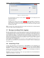
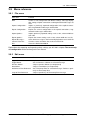
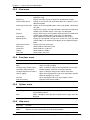
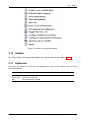
Software Manual
DeviceNet-Module
canAnalyser3 Module
for ODVA™ DeviceNet™ Protocol Interpretation
HMS Technology Center Ravensburg GmbH
Helmut-Vetter-Straße 2
88213 Ravensburg
Germany
Tel.: +49 751 56146-0
Fax: +49 751 56146-29
Internet: www.hms-networks.de
E-Mail: [email protected]
Support
In case of unsolvable problems with this product or other HMS products
please contact HMS in written form:
Fax: +49 751 56146-29
E-Mail: [email protected]
Further international support contacts can be found on our webpage
www.hms-networks.de
Copyright
Duplication (copying, printing, microfilm or other forms) and the electronic
distribution of this document is only allowed with explicit permission of
HMS Technology Center Ravensburg GmbH. HMS Technology Center
Ravensburg GmbH reserves the right to change technical data without
prior announcement. The general business conditions and the regulations
of the license agreement do apply. All rights are reserved.
Registered trademarks
All trademarks mentioned in this document and where applicable third
party registered are absolutely subject to the conditions of each valid label right and the rights of particular registered proprietor. The absence of
identification of a trademark does not automatically mean that it is not
protected by trademark law.
Document number: 4.02.0148.20000
Version: 1.4
Contents
Contents
1 Overview
1
2 Installation and start-up
2.1 System requirements . . . . . . . . . . . . . . . . . . . . . . . . . . . . . . . .
2.2 Installation . . . . . . . . . . . . . . . . . . . . . . . . . . . . . . . . . . . . .
2.3 Starting the DeviceNet-Module . . . . . . . . . . . . . . . . . . . . . . . . . . .
3
3
3
3
3 Usage of the DeviceNet-Module
3.1 Scope of functions . . . . . . . . . . . . . . .
3.2 Message display . . . . . . . . . . . . . . . .
3.2.1 Display of the receive status . . . . . .
3.3 Message interpretation . . . . . . . . . . . . .
3.3.1 I/O Messages . . . . . . . . . . . . . .
3.3.2 Fragmented I/O Messages . . . . . . .
3.3.3 Unconnected Messages . . . . . . . .
3.3.4 Explicit Messages . . . . . . . . . . . .
3.3.5 Fragmented Explicit Messages . . . . .
3.3.6 Duplicate MAC ID Check Messages . .
3.3.7 Messages of the Offline Connection Set
3.3.8 Reserved Messages . . . . . . . . . .
3.3.9 Invalid Messages . . . . . . . . . . . .
3.4 Configuration of fragmented I/O Messages . .
3.5 Configuration of Explicit Connections . . . . .
3.6 Message filtering . . . . . . . . . . . . . . . .
3.7 Message recording (Online logging) . . . . . .
3.8 Converting a Trace . . . . . . . . . . . . . . .
3.9 Menu reference . . . . . . . . . . . . . . . . .
3.9.1 File menu . . . . . . . . . . . . . . . .
3.9.2 Edit menu . . . . . . . . . . . . . . . .
3.9.3 View menu . . . . . . . . . . . . . . .
3.9.4 Functions menu . . . . . . . . . . . . .
3.9.5 Options menu . . . . . . . . . . . . . .
3.9.6 Help menu . . . . . . . . . . . . . . .
3.10 Toolbar . . . . . . . . . . . . . . . . . . . . .
3.11 Status bar . . . . . . . . . . . . . . . . . . .
3.12 Hotkeys . . . . . . . . . . . . . . . . . . . . .
3.13 Windows Registry . . . . . . . . . . . . . . .
DeviceNet Module for canAnalyser3
iii
.
.
.
.
.
.
.
.
.
.
.
.
.
.
.
.
.
.
.
.
.
.
.
.
.
.
.
.
.
.
.
.
.
.
.
.
.
.
.
.
.
.
.
.
.
.
.
.
.
.
.
.
.
.
.
.
.
.
.
.
.
.
.
.
.
.
.
.
.
.
.
.
.
.
.
.
.
.
.
.
.
.
.
.
.
.
.
.
.
.
.
.
.
.
.
.
.
.
.
.
.
.
.
.
.
.
.
.
.
.
.
.
.
.
.
.
.
.
.
.
.
.
.
.
.
.
.
.
.
.
.
.
.
.
.
.
.
.
.
.
.
.
.
.
.
.
.
.
.
.
.
.
.
.
.
.
.
.
.
.
.
.
.
.
.
.
.
.
.
.
.
.
.
.
.
.
.
.
.
.
.
.
.
.
.
.
.
.
.
.
.
.
.
.
.
.
.
.
.
.
.
.
.
.
.
.
.
.
.
.
.
.
.
.
.
.
.
.
.
.
.
.
.
.
.
.
.
.
.
.
.
.
.
.
.
.
.
.
.
.
.
.
.
.
.
.
.
.
.
.
.
.
.
.
.
.
.
.
.
.
.
.
.
.
.
.
.
.
.
.
.
.
.
.
.
.
.
.
.
.
.
.
.
.
.
.
.
.
.
.
.
.
.
.
.
.
.
.
.
.
.
.
.
.
.
.
.
.
.
.
.
.
.
.
.
.
.
.
.
.
.
.
.
.
.
.
.
.
.
.
.
.
.
.
.
.
.
.
.
.
.
.
.
.
.
.
.
.
.
.
.
.
.
.
.
.
.
.
.
.
.
.
.
.
.
.
.
.
.
.
.
.
.
.
.
.
.
.
.
.
.
.
.
.
.
.
.
.
.
.
.
.
.
.
.
.
.
.
.
.
.
.
.
.
.
.
.
.
.
.
.
.
.
.
.
.
.
.
.
.
.
.
.
.
.
.
.
.
.
.
.
.
.
.
.
.
.
.
.
.
.
.
.
.
.
.
.
.
.
.
.
.
.
.
.
.
.
.
.
.
.
.
.
.
.
.
.
.
.
.
.
.
.
.
.
.
.
.
.
.
.
.
.
.
.
.
.
.
.
.
.
.
.
.
.
.
.
.
.
.
.
.
.
.
.
.
.
.
.
.
.
.
.
.
.
.
.
.
.
.
.
.
5
5
6
7
8
8
8
9
10
10
11
11
11
11
12
13
15
16
16
17
17
17
18
18
18
18
19
19
20
21
Copyright HMS Technology Center Ravensburg
Contents
A Registers
A.1 Definitions, acronyms, abbreviations for DeviceNet . . . . . . . . . . . . . . . .
A.2 Specifications . . . . . . . . . . . . . . . . . . . . . . . . . . . . . . . . . . . .
A.3 Trademark Acknowledgements . . . . . . . . . . . . . . . . . . . . . . . . . . .
DeviceNet Module for canAnalyser3
iv
23
23
24
25
Copyright HMS Technology Center Ravensburg
Chapter 1
Overview
The DeviceNet-Module (Fig. 1.1) is an add-on module for the canAnalyser3 and provides the
monitoring of the received layer-2 messages in DeviceNet™ notation. The messages are displayed in accordance with the DeviceNet standard of the ODVA™ (see Appendix A.2). In addition, it is possible to show the corresponding layer-2 messages of the protocol-specific interpretations.
Figure 1.1: DeviceNet-Module
DeviceNet Module for canAnalyser3
1
Copyright HMS Technology Center Ravensburg
Chapter 2
Installation and start-up
2.1
System requirements
The condition for installation of the DeviceNet-Module is an installed, working canAnalyser3.
2.2
Installation
To install the DeviceNet-Module, insert the provided program CD into the drive of your computer
and run the file "DeviceNetModule30.exe".
Follow the instructions of the installation program.
2.3
Starting the DeviceNet-Module
In order to start the DeviceNet-Module, the canAnalyser3 must first be called. The DeviceNetModule now appears in the Modules Window of the Control Panel (Fig. 2.1). From here the
module can be dragged to a CAN bus. If the analysis configuration is saved, the canAnalyser3
starts the DeviceNet-Module automatically by loading this analysis configuration the next time.
More information is given in the canAnalyser3 user’s manual.
DeviceNet Module for canAnalyser3
3
Copyright HMS Technology Center Ravensburg
Chapter 2. Installation and start-up
Figure 2.1: Control Panel
DeviceNet Module for canAnalyser3
4
Copyright HMS Technology Center Ravensburg
Chapter 3
Usage of the DeviceNet-Module
3.1
Scope of functions
The DeviceNet-Module enables received CAN messages to be interpreted in accordance with
the ODVA™ DeviceNet™ standard. It is suitable for troubleshooting and analysis of DeviceNet™
networks and systems.
The DeviceNet-Module provides the following analysis functions:
• Interpretation of the Connection ID according to Message Group, Message ID and MAC
ID
• Interpretation of layer-2 messages based on the message type and generation of a description text
• Display of interpreted DeviceNet messages in order of time of reception
• Display of the corresponding layer-2 messages
• Automatic detection and manual configuration of Explicit Connections and interpretation
of the communication between client and server
• Analysis and monitoring of the fragmentation protocol for Explicit Messages with display
by message or by fragment
• Configuration of fragmented I/O Messages, evaluation and monitoring of the fragmentation
protocol with display by message or by fragment
• Filtering according to Message Group, Message ID and MAC ID
• Filtering according to message type
• Export and import of the Explicit Connections, the fragmented I/O Messages and the filter
settings
• Export of the received messages in CSV format
• Message recording in a CSV file
As different instances of the DeviceNet-Module can be started from the Control Panel, it is possible to adapt each DeviceNet-Module individually to the messages or Message Groups to be
analyzed (only possible with canAnalyser3 standard).
DeviceNet Module for canAnalyser3
5
Copyright HMS Technology Center Ravensburg
Chapter 3. Usage of the DeviceNet-Module
Figure 3.1: DeviceNet-Module
3.2
Message display
The messages are listed in order of their reception with the following information (Fig. 3.1):
Column
Meaning
No
Time (rel/abs)
Consecutive number of the received DeviceNet messages
Time stamp of the reception, optionally absolute in UTC time format or
relative to the previously received message; the display of hours can
be switched on and off by right-clicking on the column heading
Reception status
Message Group
Message ID(Message ID)
Node number of the message sender (Source MAC-ID)
Node number of the message receiver (Destination MAC-ID)
Message type
Transaction ID
Displays whether it is a request or a response message
Display of the fragmentation information
Interpretation text of the DeviceNet message
State
Msg Grp
Msg ID (hex/dec)
Src MAC ID (hex/dec)
Dst MAC ID (hex/dec)
Msg Usage
XID
RR
Fragmentation
Description
Various values can be displayed in hexadecimal or decimal format. The display type for the
individual columns is selected via the menu View or by right mouse click on the corresponding
column header.
A DeviceNet message can be displayed over several lines if the window is not wide enough to
display all information. For this, the menu item View | Word wrap lines is enabled.
To display the corresponding layer-2 message below a DeviceNet message, the menu item View
| Display Layer-2 Messages has to enabled.
DeviceNet Module for canAnalyser3
6
Copyright HMS Technology Center Ravensburg
3.2. Message display
3.2.1
Display of the receive status
The column Status visualizes the receive status with various icons:
Status
Meaning
Connecting: A new connection was added to the list
Timeout: Latency time when transmitting an Acknowledge Fragment or an Unconnected Response was exceeded
Unknown message: A message failed to interpret or a protocol error during interpretation was encountered
Message overflow: Messages were lost
Invalid message: An error frame was received
Invalid message: A remote CAN frame CAN was received
Invalid message: An extended CAN frame was received
DeviceNet Module for canAnalyser3
7
Copyright HMS Technology Center Ravensburg
Chapter 3. Usage of the DeviceNet-Module
3.3
Message interpretation
The DeviceNet™ specification of the ODVA™ only allows standard CAN messages with 11-bit
identifier and only these messages are interpreted by the DeviceNet-Module. For extended
CAN frames, remote frames and error frames, no interpretation takes place. These messages
are displayed with a corresponding description text.
Note: With default settings, the canAnalyser3 is not in Tx-passive mode, i.e. acknowledges
can be actively set and errors signaled. For some DeviceNet™ applications, such as the
analysis of the conformance test, it is necessary to prevent the active bus access. To this end,
the option Tx passive is selected in the controller properties of the Control Panel.
Note: If message interpretation fails, for example because the message has an unexpected
length, the transmitted data are displayed byte-wise.
3.3.1
I/O Messages
I/O Messages are used to transmit application-specific data. The DeviceNet-Module displays the
following information for I/O Messages:
• Message Group
• Message ID
• Source MAC ID
• Description text with the transmitted data displayed byte-wise
The following messages are always treated as I/O Messages:
• Message Group 1, Message ID 0 - 15
• Message Group 2, Message ID 0, 1, 2, 5
• Message Group 3, Message ID 0 - 4
Note: The signal module can be used to interpret the data of I/O Messages and their meaning
displayed in plaintext.
3.3.2
Fragmented I/O Messages
If I/O Messages are transmitted fragmented, the user must configure this manually, as DeviceNet™ does not provide a mechanism to detect fragmented I/O Messages automatically.
Fragmented I/O Messages are configured via the command Functions | Configure frag. I/O
messages... and are described in section 3.4.
If the menu item Options | Single Fragment Mode is enabled, the fragmentation protocol is
interpreted for each received fragment and displayed in the column Fragmentation. The description text of the message contains the further data bytes.
If the menu item Options | Single Fragment Mode is not enabled, the individual fragments
are reassembled and the message is only displayed after the last fragment is received. The
fragmentation column gives the number of fragments, the description text of the reassembled
message displays the first 64 data fragments. In this mode the fragmentation protocol is
DeviceNet Module for canAnalyser3
8
Copyright HMS Technology Center Ravensburg
3.3. Message interpretation
monitored and if infringed an Error Message is issued in the fragmentation column.
Note: An entry in the list of fragmented messages is only relevant if no Explicit Connection exists
via this Connection ID.
3.3.3
Unconnected Messages
Unconnected Messages can be transmitted via the Unconnected Message Manager (UCMM)
(Request: Message Group 3, Message ID 6; Response: Message Group 3, Message ID 5) or
via the Group 2 Only Unconnected Port (Request: Message Group 2, Message ID 6; Response:
Message Group 2, Message ID 3).
For Unconnected Messages, the following information is interpreted:
• Message Group
• Message ID
• Source and Destination MAC ID
• XID-bit
• Request/Response bit
• Service Code
Further interpretation depends on the Service Code:
• Open Explicit Messaging Connection: For the request, the requested Message Format, the Message Group and the Source Message ID are displayed via which the connection is to be opened. For the Response, the Message Format used, the Destination and
Source Message ID via which the connection is opened and the Connection Instance ID
are interpreted.
• Close Connection: For the request, the Connection Instance ID is issued. The response
only contains the Service Code.
• Allocate Master/Slave Connection Set: For the request, the Class and Instance IDs
and the individual flags of the Allocation Choice bytes are issued. For the response, the
Message Format used is interpreted.
• Release Master/Slave Connection Set: For the request, the Class and Instance IDs and
the individual flags of the Release Choice bytes are issued. The response only contains
the Service Code.
• Error Response: For this response message, the General Error Code and the Additional
Code are interpreted.
• Device Heartbeat Message: For this response message, the Identity Object Instance
ID, the Device State, the flags Event, System Fault, User Fault, Device-Fault and the Configuration Consistency Value are displayed.
• Device Shutdown Message: For this response message, the Class and Instance IDs
and the Shutdown Code are displayed.
• For all other services, the transferred data are displayed byte-wise.
DeviceNet Module for canAnalyser3
9
Copyright HMS Technology Center Ravensburg
Chapter 3. Usage of the DeviceNet-Module
3.3.4
Explicit Messages
After the connection has been successfully opened via the service Open Explicit Messaging
Connection or Allocate Master/Slave Connection Set, messages that are transmitted via these
connections are interpreted as Explicit Messages.
The following information is analyzed for Explicit Messages:
• Message Group
• Message ID
• Source and Destination MAC ID
• XID-bit
• Request/Response bit
• Service Code
Further interpretation is carried out depending on the Service Code:
• Set Attribute Single: For the request, the Class, Instance and Attribute IDs are analyzed
and the further data are displayed byte-wise. For the response, the transmitted data are
displayed byte-wise.
• Get Attribute Single: For the request, the Class, Instance and Attribute IDs are analyzed.
For the response, the transmitted data are displayed byte-wise.
• Error Response: For these messages, the General Error Code and the Additional Code
are interpreted.
• Allocate and Release Master/Slave Connection Set: These services are interpreted
as described in the section Unconnected Messages.
• For all other services, the Class and Instance IDs are analyzed for the request and the
further data are displayed byte-wise. For the response, the transmitted data are displayed
byte-wise.
In addition, the service and class names defined in DeviceNet™ and the names for the General
Error Codes are displayed with the interpretation.
3.3.5
Fragmented Explicit Messages
Fragmented Explicit Messages are interpreted according to the set mode:
If the menu item Options | Single Fragment Mode is enabled, the fragmentation protocol is
interpreted for every received fragment and displayed in the fragmentation column. The further
data bytes are displayed in the description text of the message.
If the menu item Options | Single Fragment Mode is not enabled, the individual fragments are
reassembled and the message is only interpreted and displayed after the last acknowledge was
received. The fragmentation column displays the number of fragments (without acknowledges).
In this mode, the fragmentation protocol is monitored and if infringed an Error Message is issued
in the fragmentation column. If time monitoring is set for Fragmented Explicit Acknowledges, it
is also checked whether acknowledges are received within the required time period.
DeviceNet Module for canAnalyser3
10
Copyright HMS Technology Center Ravensburg
3.4. Configuration of fragmented I/O Messages
3.3.6
Duplicate MAC ID Check Messages
For Duplicate MAC ID Check Messages, the DeviceNet-Module displays the following information:
• Message Group
• Message ID
• Destination MAC ID
• Request/Response bit
• Description text with Physical Port Number, Vendor ID and Serial Number
3.3.7
Messages of the Offline Connection Set
The following information is displayed for the messages of the Offline Connection Set:
• Message Group
• Message ID
• Description text with the transmitted data displayed byte-wise
3.3.8
Reserved Messages
In DeviceNet™, the messages are reserved with the CID 0x7C0 - 0x7EB. For these messages
the DeviceNet-Module displays the following information:
• Message Group
• Message ID
• Description text with the transmitted data displayed byte-wise
3.3.9
Invalid Messages
In DeviceNet™, the messages with the CID 0x7F0 - 0x7FF are declared invalid. The following
information is displayed for invalid DeviceNet messages:
• Message Group
• Message ID
• Description text with the transmitted data displayed byte-wise
DeviceNet Module for canAnalyser3
11
Copyright HMS Technology Center Ravensburg
Chapter 3. Usage of the DeviceNet-Module
Figure 3.2: Dialog for configuration of fragmented I/O Messages
3.4
Configuration of fragmented I/O Messages
The list of the fragmented I/O Messages contains all user-defined I/O Messages for which the
fragmentation protocol is analyzed. All I/O Messages not contained in the list are regarded as
unfragmented.
Via the menu item Functions | Configure frag. I/O Messages..., the dialog from Fig. 3.2 is
displayed. Individual messages or all messages can be selected from the list of fragmented
messages and deleted. New fragmented I/O Messages can be defined via the edit boxes by
entering the Message Group, Message ID and Source MAC ID or the Connection ID (CAN
identifier).
Attention: As long as the dialog is open, the message reception of the DeviceNet-Module remains stopped.
DeviceNet Module for canAnalyser3
12
Copyright HMS Technology Center Ravensburg
3.5. Configuration of Explicit Connections
Figure 3.3: Dialog for the configuration of Explicit Connections
3.5
Configuration of Explicit Connections
Via the menu item Functions | Configure Explicit Connections..., the dialog (Fig. 3.3) with the
list of Explicit Connections is displayed. An Explicit Message can only be interpreted when an
Explicit Connection is available for this message in the list, otherwise the message is treated as
an I/O Message.
The dialog displays all active connections. In addition, individual connections or all connections
can be selected and deleted. Via the edit boxes it is possible to add new Explicit Connections
to the list by entering the Message Group, the Message ID and MAC ID of the server and client
and of the Message Format. Entry of the Connection Instance ID is optional.
An Explicit Connection can be created via the following messages:
• Message Group 1, Message ID 0 - 15
• Message Group 2, Message ID 3 (response), 4 (request)
• Message Group 3, Message ID 0 - 4
Via Message Group 2, only the Predefined Master/Slave Connection Set for Explicit Connections
is supported.
When the menu item Functions | Connection Auto Detection is enabled, an Explicit Connection is added to the list on correct reception of the services Open Explicit Messaging Connection
and Allocate Master/Slave Connection Set. In the event of conflicts with existing entries, these
are removed before a new connection is added to the list.
DeviceNet Module for canAnalyser3
13
Copyright HMS Technology Center Ravensburg
Chapter 3. Usage of the DeviceNet-Module
An Explicit Connection can only be deleted from the list manually. The services Close Connection and Release Master/Slave Connection Set have no influence on the contents of the
connection table.
In addition, time monitoring for the Unconnected Responses and for Acknowledge Fragments
can be set via the connection dialog. The latency time for Unconnected Responses is relevant
for the automatic connection detection on reception of the services Open Explicit Messaging
Connection and Allocate Master/Slave Connection Set. An Explicit Connection is only detected
when the response is transmitted within the latency time. If the latency time is set to 0, no
monitoring is carried out.
Attention: As long as the dialog is open, the message reception of the DeviceNet-Module
remains stopped.
Note: The filter settings have no influence on the automatic connection detection.
DeviceNet Module for canAnalyser3
14
Copyright HMS Technology Center Ravensburg
3.6. Message filtering
Figure 3.4: Display of the three filter views: filtering by Message Group, message usage or MAC ID
3.6
Message filtering
The DeviceNet-Module has an integrated filter on the left side of the window. The filter offers
three views (Fig. 3.4), which are used both for configuration and to display the current filter
settings.
Filtering comprises the information contained in the Connection ID and the message type. For
simple configuration of the filter, it provides three views, which can be selected via tabsheets.
The filter views are displayed as tree structures and the individual elements are enabled or
disabled via check boxes.
If an element and all its sub-elements are displayed, the check box is checked ( ). If an element
with all sub-elements is filtered out, the checkbox is unchecked ( ). If below an element there
are both messages that are displayed and messages that are filtered out, this check box is
checked with a gray background ( ). In addition, the complete filter can be opened or closed via
a pop-up menu.
The following filter views are available:
• Filtering by Message Group, Message ID and MAC ID
All messages are displayed in a tree structure (Fig. 3.4). The messages are arranged
hierarchically according to Message Group, Message ID and MAC ID. In this tree, it is
possible to define for each individual DeviceNet message whether it is to be displayed or
filtered out.
• Filtering by message type
DeviceNet Module for canAnalyser3
15
Copyright HMS Technology Center Ravensburg
Chapter 3. Usage of the DeviceNet-Module
Figure 3.5: Conversion of a trace
All message types are listed in a tree structure (Fig. 3.4). Any message type can be
displayed or filtered out.
• Filtering by MAC ID
All MAC IDs are listed in a tree structure (Fig. 3.4), under each MAC ID a distinction is
made between the individual message types. The specified MAC ID always refers to the
MAC ID in the Connection ID. In this view it is possible to select which messages are to be
received for each node.
Note: A change in filter settings only affects the messages received after the setting change but
not the messages already received before that.
3.7
Message recording (Online logging)
Message recording enables received and interpreted messages to be written directly into file.
The DeviceNet messages are saved in ASCII format as a CSV (comma separated value) file and
can be imported for analysis and further processing in standard tools such as Microsoft Excel.
At the beginning of logging, it is enquired to which file the messages are to be written. The
display formats and the interpretation mode are adopted at the beginning of logging. Changing
the format during logging has no influence on the format in the file. Changes in filter settings, on
the other hand, take immediate effect.
Online logging can be stopped by user at any time or it will be stopped automatically when free
disk space is less than 25 MiB. The size of one trace file is limited to 1 GiB, then a following trace
file will be created.
3.8
Converting a Trace
A binary trace generated via the canAnalyser3’s Trace-module can be interpreted by the
DeviceNet-Module and saved to a CSV file. To start conversion, the menu item File | Convert
Trace File... is selected. This opens the dialog (Fig. 3.5), in which the trace file to be interpreted
and the name of the CSV file to be generated is defined. After acknowledging the dialog with
the OK button, the interpretation is started.
Attention: During the interpretation of traces, message reception of the DeviceNet-Module is
stopped and the Module is inaccessible.
DeviceNet Module for canAnalyser3
16
Copyright HMS Technology Center Ravensburg
3.9. Menu reference
3.9
Menu reference
3.9.1
File menu
Menu item
Function
New
Creates a new configuration with default settings: Message display,
filter settings, Explicit Connections and fragmented I/O Messages are
reset
Imports a previously exported configuration of the explicit connections, fragmented I/O Messages and the filter
Exports the current configuration of the explicit connections, fragmented I/O Messages and the filter
Imports previously exported settings such as font, column width etc.
from a file
Exports the current settings such as font, column width etc. in a file
Saves all the messages in the internal display buffers to an ASCII file
Converts a trace and writes the result to an ASCII file
Closes the DeviceNet-Module
Import Configuration...
Export Configuration...
Import Options...
Export Options...
Export Messages...
Convert Trace File...
Exit
Explanations for exporting and importing solely settings you will find in chapter The term analysis configuration of the canAnalyser3 user manual.
3.9.2
Edit menu
Menu item
Function
Copy CSV
Toggle Marker
Previous Marker
Next Marker
Set/Release Time Reference
Copies marked lines CSV formatted to clipboard
Sets or Removes a Marker for selected message
Jumps to previous Marker (no wraparound)
Jumps to next Marker (no wraparound)
Sets Timestamp Zero for selected message / Releases previously set Timestamp Zero
Jumps to previously set Timestamp Zero message
Jump to Time Reference
DeviceNet Module for canAnalyser3
17
Copyright HMS Technology Center Ravensburg
Chapter 3. Usage of the DeviceNet-Module
3.9.3
View menu
Menu item
Function
Time relative
Display of the time stamp absolute or relative to the previously displayed message
Display of the Message ID in decimal or hexadecimal notation
Display of the Source and Destination MAC ID in decimal or hexadecimal notation
Display of the corresponding layer-2 messages below a DeviceNet
message
Display of the layer-2 message identifier in decimal or hexadecimal
notation (only available if layer-2 messages are displayed)
Display of the layer-2 message data field in decimal or hexadecimal
notation (only available if layer-2 messages are displayed)
Draws additional horizontal guides between the lines in grey
Displays the interpreted message over several lines if the specified
column width is not sufficient for the display of the complete interpretation
Display of the latest messages
Shows/Hides the filter trees pane
Shows/hides the scroll view
Shows/Hides the toolbar
Shows/Hides status bar
Msg ID hex
Src/Dest MAC ID hex
Show Layer 2 Message
ID hex
Data hex
Draw Guides
Word wrap lines
Show recent Frames
Filter Trees
Scroll View
Toolbar
Status Bar
3.9.4
Functions menu
Menu item
Function
Start
Stop
Configure frag. I/O Messages...
Connection Auto Detection
Configure Explicit Connections...
Online Logging...
Starts message reception of the DeviceNet-Module
Stops message reception
Opens a dialog to configure the fragmented I/O messages
Enables/disables automatic connection detection
Opens a dialog to configure the explicit connections
Writes the interpreted messages to an ASCII file in parallel
with their displaying on screen
Clears the display and resets the reception counter
Regulates ideal column widths
Clear All
Autosize Columns
3.9.5
Options menu
Menu item
Function
Single Fragment Mode
Switches between fragment- and message-oriented display of the
fragmentation protocol
Opens a dialog to select the font in which the messages are to be
displayed
Font...
3.9.6
Help menu
Menu item
Function
Help Topics
About...
Opens the online help of the DeviceNet-Module
Displays the version information of the DeviceNet-Module
DeviceNet Module for canAnalyser3
18
Copyright HMS Technology Center Ravensburg
3.10. Toolbar
Figure 3.6: Toolbar of the DeviceNet-Module
3.10
Toolbar
The main functions of the DeviceNet-Module can also be called via the toolbar (Fig. 3.6).
3.11
Status bar
The status bar contains an LED icon that displays the status of the Control Panel or of the
DeviceNet-Module:
LED color
Meaning
Green:
Flashing red:
Red:
Control Panel and DeviceNet-Module are started
Control Panel stopped
DeviceNet-Module stopped
DeviceNet Module for canAnalyser3
19
Copyright HMS Technology Center Ravensburg
Chapter 3. Usage of the DeviceNet-Module
3.12
Hotkeys
TAB
F1
F2
Shift+F2
Ctrl+F2
F5
Shift+F5
F6
F8
F11
Ctrl+C
Ctrl+E
Ctrl+I
Ctrl+M
Ctrl+N
Ctrl+O
Ctrl+S
Ctrl+W
Ctrl+X
PageDown
PageUp
Ctrl+PageDown
Ctrl+PageUp
Ctrl+0
Ctrl+1..9
Switch between filter trees and message view
Online-Help
Go to Next Marker
Go to Previous Marker
Toggle Marker
Start message reception
Stop message reception
Enable/disable inline logging
Clear View
Show/hide filter trees
Copy marked lines CSV formatted to clipboard
Export the received messages to a file
Show fragmented I/O messages dialog
Switch fragment- and message-oriented display
Create a new configuration
Load application settings from file
Save application settings from file
Close the application window
Show explicit connections dialog
Scroll one page ahead in current View
Scroll one page backward in current View
Scroll 1000 messages ahead in current View
Scroll 1000 messages backward in current View
Jump to Time Reference message
Jump to 10%..90% of current View
DeviceNet Module for canAnalyser3
20
Copyright HMS Technology Center Ravensburg
3.13. Windows Registry
Figure 3.7: Registry settings of the DeviceNet-Module
3.13
Windows Registry
A few additional display settings can be done in the Windows Registry at
HKCU\Software\IXXAT\canAnalyser3\Modules\DeviceNet-Module\Settings
(Fig. 3.7):
• DataBytesShown is a DWORD key setting the maximum number of databytes displayed
for fragmented messages. Default value is 100.
• ExpReassembling is a DWORD key setting the number of explicit fragments that are
reassembled. Default value is 64.
• IOReassembling is a DWORD key setting the number of I/O fragments that are reassembled. Default value is 64.
• L2FragShown is a DWORD key setting the maximum number of lines to be shown when
layer-2 messages are displayed (see also (View | Show Layer 2 message 3.2)). Default
value is 10.
If a mentioned registry key is not existing, it can be created with the context menu of the registry
editor via command New | DWORD-value (32bit)
DeviceNet Module for canAnalyser3
21
Copyright HMS Technology Center Ravensburg
Appendix A
Registers
A.1
Definitions, acronyms, abbreviations for DeviceNet
Bit-Strobe Connection 1:N connection between a master/client (Bit-Strobe Command)
and one or more slaves/servers (Bit-Strobe Response).
Change-of-State/Cyclic Connection Point-to-point connection between a slave/client
(COS/Cyclic Message) and a master/server (COS/Cyclic Acknowledge).
With change of state, data are produced by the client when they have
been altered, with cyclic when a configurable time interval has elapsed.
The message can be acknowledged by the server as an option.
Connection ID
DeviceNet defines the CAN identifier of a message as the Connection
ID and divides this into 3 fields. Thus a further sub-division of the CAN
identifier is achieved, such as into Message Group, Message ID and
MAC ID.
Explicit Message
Message type in DeviceNet with which the meaning of the message
is defined by the data field of the CAN message. This message type
is used for configuration and diagnostics. Corresponds to the SDO in
CANopen.
Group-2-Only Server Designation for a device in DeviceNet that only receives messages
in Message Group 2. Uses the Predefined Master/Slave Connection Set
only.
Group-2-Only Unconnected Port of the Predefined Master/Slave Connection Set
With the UCMM Port, only Explicit Connections can be set up, whereas
with the Group-2-Only Unconnected Port I/O Connections of the
Predefined Master/Slave Connection Set can be set up.
Group-2 Server
Designation for a device in DeviceNet that supports the UCMM Port and
also the Predefined Master/Slave Connection Set.
I/O Message
Message type in DeviceNet with which the meaning of the message is
defined by the identifier of the CAN message. This message type is used
for the exchange of process data in a DeviceNet system. Corresponds
to the PDO in CANopen.
DeviceNet Module for canAnalyser3
23
Copyright HMS Technology Center Ravensburg
Appendix A. Registers
MAC ID (Media Access Control Identifier) Node number of a DeviceNet device in the
network. For Explicit Messages, DeviceNet distinguishes between
Source MAC ID (source nodes) and Destination MAC ID (destination
nodes). For I/O Messages only the Source MAC ID is used.
Message Format
The message format of a connection defines for Explicit Messages with
which format the class and instance are addressed. A DeviceNet node
distinguishes here between 8-bit and 16-bit addressing of class and instance, so that a total of 4 different modes are available: DeviceNet
8/8 to DeviceNet 16/16 (8-bit Class ID/8-bit Instance ID to 16-bit Class
ID/16-bit Instance ID)
Message Group
DeviceNet divides the available CAN identifiers into a total of 4 Message
Groups.
Message ID
For each DeviceNet node in the network there is a certain number of
message identifiers available in the individual Message Groups.
Multicast Poll Connection 1:N connection between a master/client (Multicast Command)
and one or more slaves/servers (Multicast Response). New I/O Message type, was specified with Errata 3. Otherwise similar to Poll Connection.
ODVA (Open DeviceNet Vendor Organization Inc.) User organization of all DeviceNet
users worldwide (see also www.odva.org).
Poll Connection
Point-to-point connection between a master/client (Poll Command) and
a slave/server (Poll Response).
Predefined Master/Slave Connection Set Predefined set of possible connections that a
DeviceNet node supports. Here a distinction is made between Explicit
Connections with Explicit Messages, see above, and I/O Connections
with the possible message types: Poll Connection, Bit-Strobe Connection, Change-of-State/Cyclic Connection, Multicast Poll Connection.
UCMM Port (Unconnected Message Manager Port) One of two ways to set up a connection with a DeviceNet node, the other being the Group-2-Only Unconnected Port of the Predefined Master/Slave Connection Set.
A.2
Specifications
[1]
THE CIP NETWORKS LIBRARY
Volume 1
Common Industrial Protocol
Edition 2.1
January 2005
Open DeviceNet Vendor Association, Inc. (ODVA)
[2]
THE CIP NETWORKS LIBRARY
Volume 3
DeviceNet Adaptation of CIP
Edition 1.1
DeviceNet Module for canAnalyser3
24
Copyright HMS Technology Center Ravensburg
A.3. Trademark Acknowledgements
January 2005
Open DeviceNet Vendor Association, Inc. (ODVA)
A.3
Trademark Acknowledgements
DeviceNet is a trademark of ODVA, Inc.
DeviceNet Module for canAnalyser3
25
Copyright HMS Technology Center Ravensburg