1
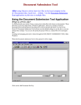
Software Manual
CANopen-Module
canAnalyser3 Module
for CANopen Protocol Interpretation
Software Version 3.2
HMS Technology Center Ravensburg GmbH
Helmut-Vetter-Straße 2
88213 Ravensburg
Germany
Tel.: +49 751 56146-0
Fax: +49 751 56146-29
Internet: www.hms-networks.de
E-Mail: [email protected]
Support
In case of unsolvable problems with this product or other HMS products
please contact HMS in written form:
Fax: +49 751 56146-29
E-Mail: [email protected]
Further international support contacts can be found on our webpage
www.hms-networks.de
Copyright
Duplication (copying, printing, microfilm or other forms) and the electronic
distribution of this document is only allowed with explicit permission of
HMS Technology Center Ravensburg GmbH. HMS Technology Center
Ravensburg GmbH reserves the right to change technical data without
prior announcement. The general business conditions and the regulations
of the license agreement do apply. All rights are reserved.
Registered trademarks
All trademarks mentioned in this document and where applicable third
party registered are absolutely subject to the conditions of each valid label right and the rights of particular registered proprietor. The absence of
identification of a trademark does not automatically mean that it is not
protected by trademark law.
Document number: 4.02.0145.20000
Version: 3.8
Contents
Contents
1 Overview
1.1 General . . . . . . . . . . . . . . . . . . . . . . . . . . . . . . . . . . . . . . .
1.2 System requirements . . . . . . . . . . . . . . . . . . . . . . . . . . . . . . . .
1.3 Highlights . . . . . . . . . . . . . . . . . . . . . . . . . . . . . . . . . . . . . .
1
1
2
2
2 Installation and start-up
2.1 System requirements . . . . . . . . . . . . . . . . . . . . . . . . . . . . . . . .
2.2 Installation . . . . . . . . . . . . . . . . . . . . . . . . . . . . . . . . . . . . .
2.3 Starting the CANopen-Module . . . . . . . . . . . . . . . . . . . . . . . . . . .
3
3
3
3
3 Use of the CANopen-Module
3.1 Message display . . . . . . . . . . . . . . . . . . . . . . .
3.1.1 Scroll View . . . . . . . . . . . . . . . . . . . . . .
3.1.2 Overwrite View . . . . . . . . . . . . . . . . . . . .
3.2 Node list . . . . . . . . . . . . . . . . . . . . . . . . . . .
3.2.1 Description of columns . . . . . . . . . . . . . . . .
3.2.2 Context menu of node list . . . . . . . . . . . . . . .
3.2.3 Import of device description files . . . . . . . . . . .
3.2.4 Object Dictionary window . . . . . . . . . . . . . . .
3.2.5 Node Properties dialog . . . . . . . . . . . . . . . .
3.3 Analysis configuration . . . . . . . . . . . . . . . . . . . .
3.3.1 New configuration . . . . . . . . . . . . . . . . . . .
3.3.2 Adding, deleting or changing communication objects
3.4 Message filtering concept . . . . . . . . . . . . . . . . . .
3.4.1 Display filtering according to object type . . . . . . .
3.4.2 Display filtering according to Node-ID . . . . . . . .
3.4.3 Reception filtering . . . . . . . . . . . . . . . . . .
3.5 Menu reference . . . . . . . . . . . . . . . . . . . . . . . .
3.5.1 File menu . . . . . . . . . . . . . . . . . . . . . . .
3.5.2 Edit menu . . . . . . . . . . . . . . . . . . . . . . .
3.5.3 View menu . . . . . . . . . . . . . . . . . . . . . .
3.5.4 Functions menu . . . . . . . . . . . . . . . . . . . .
3.5.5 Trace menu . . . . . . . . . . . . . . . . . . . . . .
3.5.6 Options menu . . . . . . . . . . . . . . . . . . . . .
3.5.7 Help menu . . . . . . . . . . . . . . . . . . . . . .
3.6 Toolbar . . . . . . . . . . . . . . . . . . . . . . . . . . . .
3.7 Status bar . . . . . . . . . . . . . . . . . . . . . . . . . .
3.8 Hotkeys . . . . . . . . . . . . . . . . . . . . . . . . . . . .
CANopen-Module for canAnalyser3
v
.
.
.
.
.
.
.
.
.
.
.
.
.
.
.
.
.
.
.
.
.
.
.
.
.
.
.
.
.
.
.
.
.
.
.
.
.
.
.
.
.
.
.
.
.
.
.
.
.
.
.
.
.
.
.
.
.
.
.
.
.
.
.
.
.
.
.
.
.
.
.
.
.
.
.
.
.
.
.
.
.
.
.
.
.
.
.
.
.
.
.
.
.
.
.
.
.
.
.
.
.
.
.
.
.
.
.
.
.
.
.
.
.
.
.
.
.
.
.
.
.
.
.
.
.
.
.
.
.
.
.
.
.
.
.
.
.
.
.
.
.
.
.
.
.
.
.
.
.
.
.
.
.
.
.
.
.
.
.
.
.
.
.
.
.
.
.
.
.
.
.
.
.
.
.
.
.
.
.
.
.
.
.
.
.
.
.
.
.
.
.
.
.
.
.
.
.
.
.
.
.
.
.
.
.
.
.
.
.
.
.
.
.
.
.
.
.
.
.
.
.
.
.
.
.
.
.
.
.
.
.
.
.
.
.
.
.
.
.
.
.
.
.
.
.
.
.
.
.
.
.
.
.
.
.
.
.
.
.
.
.
.
.
.
.
.
.
.
.
.
.
.
.
.
.
.
.
.
.
.
.
.
.
.
.
.
.
.
.
.
.
.
.
.
.
.
.
5
5
6
7
8
9
11
12
14
15
17
17
18
20
20
21
21
23
23
23
24
25
25
26
26
27
27
28
Copyright HMS Technology Center Ravensburg
Contents
A Registers
A.1 Definitions, Acronyms, Abbreviations with CANopen . . . . . . . . . . . . . . . .
A.2 Specifications . . . . . . . . . . . . . . . . . . . . . . . . . . . . . . . . . . . .
29
29
33
B Copyrights
B.1 Copyright . . . . . . . . . . . . . . . . . . . . . . . . . . . . . . . . . . . . . .
B.2 Additional Copyrights . . . . . . . . . . . . . . . . . . . . . . . . . . . . . . . .
35
35
35
CANopen-Module for canAnalyser3
vi
Copyright HMS Technology Center Ravensburg
Chapter 1
Overview
1.1
General
The CANopen-Module (Fig. 1.1) is an add-on module for the canAnalyser3 and provides the
display of received layer-2 messages in CANopen notation. The messages are displayed in
accordance with the configuration and the CAN-in-Automation [1] A.2 [7] A.2 specified communication objects, assigned to individual nodes, their content extracted and output in plaintext.
In addition, it is possible to display the corresponding layer-2 messages of the protocol-specific
interpretation.
The interpretation is based on a network model (analysis configuration) in which the individual
nodes connected to the CANopen network to be analyzed are described. This description can
be carried out by reading in device description files (EDS-, DCF- and XDD-files)[5] A.2 [6] A.2, by
simple profile assignment (default configuration), by online node scan, or completely manually.
Figure 1.1: CANopen-Module
CANopen-Module for canAnalyser3
1
Copyright HMS Technology Center Ravensburg
Chapter 1. Overview
1.2
System requirements
• Installed canAnalyser3
1.3
Highlights
• Interpretation of layer-2 messages in CANopen format
• Continuous display of the bus traffic in real-time
• Cumulated display sorted by CAN identifier in ascending order with highlighted changed
data and statistical data
• Output of data contents and descriptive names of objects transmitted in PDOs
• Nondestructive display filter according to node-ID and object type (SDO, PDO, NMT etc.)
• Output of segmented SDO transfers as complete message or individual messages
• Freely configurable CAN identifiers for every node with import of EDS/DCF/XDD files
• Support of SDO block transfer protocols, multiplex PDOs and SRDOs
• Indication of non-interpretable messages
• Display of the raw (non-interpreted) CAN telegrams
• Analysis of the SDO command and protocol bytes in plaintext
• Interpretation of the LSS protocol [4] A.2
• Interpretation of the Flying Master protocol [3] A.2
• On-line logging of the interpreted messages to file
• Configurable display color for each object type
• Colored background of all messages related to a certain node
• Network scan with automatic identification of device profile and device identity
• Changing of device profiles during runtime
CANopen-Module for canAnalyser3
2
Copyright HMS Technology Center Ravensburg
Chapter 2
Installation and start-up
2.1
System requirements
The requirement for installation of CANopen-Modules is an installed, functional canAnalyser3 or
higher.
2.2
Installation
To install the CANopen-Module, insert the provided program CD into the drive of your computer.
Windows will automatically start the installation program of the CANopen-Module. If this is not
the case, please run the file "CANopenModule32.exe".
2.3
Starting the CANopen-Module
In order to start the CANopen-Module, the canAnalyser3 must first be called. The module now
appears in the Modules Window of the Control Panel (Fig. 2.1). From here, the module can
be dragged to a CAN line. For more information, see the canAnalyser3 user’s manual.
If the configuration is saved, the canAnalyser3 starts the CANopen-Module automatically by
loading this analysis configuration the next time.
Starting separate instances of CANopen-Module on different CAN lines is supported (not possible with canAnalyser3 lite). These instances work independently and can therefore be configured
individually (with regard to filter settings, device description files, colors etc.)
CANopen-Module for canAnalyser3
3
Copyright HMS Technology Center Ravensburg
Chapter 2. Installation and start-up
Figure 2.1: Control Panel with CANopen-Module
CANopen-Module for canAnalyser3
4
Copyright HMS Technology Center Ravensburg
Chapter 3
Use of the CANopen-Module
3.1
Message display
Interpreted messages can be displayed one by one in the order of their reception, or cumulated
sorted by CAN identifier in ascending order.
The one by one display is referred to as scroll view and can be found on the Scroll tab,
whereas the cumulated view is displayed on the Overwrite tab. Use hotkey Ctrl-TAB to
switch between the views.
For each of the views, the following display options can be set:
• Various column values can be displayed in hexadecimal or decimal format. The display
format for the individual columns is selected via the menu View, the toolbar or by right
mouse click on the corresponding column header.
• To display the corresponding layer-2 messages in two extra columns named ID and Data,
the menu command View | Show also raw CAN data has to be enabled.
• The font and face can be freely selected.
This is done using the menu command
Options | Font...
CANopen-Module for canAnalyser3
5
Copyright HMS Technology Center Ravensburg
Chapter 3. Use of the CANopen-Module
3.1.1
Scroll View
In this view, the messages are listed in order of their reception with the following information
(Fig. 1.1):
Column
Meaning
No
Time (rel/abs)
Continuous distinct number of received message.
Time stamp of the reception, either absolute in UTC time format or relative
to the previously received message; the display of hours can be switched
on and off by right-clicking on the column heading
CAN-identifier of received message. This column is visible only if layer-2
messages display is enabled.
Received CAN data bytes readout. This column is visible only if layer-2
messages display is enabled.
CANopen Node-ID in decimal or hexadecimal notation, depending on
whether the View menu item Node-ID hex is checked or not.
Name of the device according to its device description file.
Type of CANopen communication object. The following object types are
distinguished: Server-SDO (SSDO), Client-SDO (CSDO), Transmit-PDO
(TPDO), Receive-PDO (RPDO), Multiplex-RPDO (M-RPDO), MultiplexTPDO (M-TPDO), Network management (NMT), Emergency object
(Emergency), Node error control (Monitoring), Time stamp object (Timestamp), Sync Object (Sync), Layer setting services (LSS), Flying master
message (FLY MASTER), Transmit safety relevant data object (TSRDO),
Receive safety relevant data object (RSRDO). The relative consecutive
number of the object is appended where applicable.
Interpreted CANopen message. This multi-line column finally shows the
plaintext CANopen message.
ID (hex/dec)
Data (hex/dec)
Node-ID (dec/hex)
Device Name
Object Type
Message
CANopen-Module for canAnalyser3
6
Copyright HMS Technology Center Ravensburg
3.1. Message display
Figure 3.1: Overwrite View
3.1.2
Overwrite View
On the Overwrite tab (Fig. 3.1), the messages are listed by their CAN-identifier in ascending
order. The last received information of a message is always displayed. A change detection
working character by character highlights changed data in color. The change detection compares
to the most recently received message contents. Additional columns show reception statistics.
The following information is listed in detail:
Column
Meaning
Counter
Cycletime
Total number of received messages of this identifier.
Time elapsed since the last reception of this message; by right-clicking on the
column heading, the display of hours and minutes can be switched on or off.
Minimum cycletime occurred, i.e. measured so far; by right-clicking on the
column heading, the display of hours and minutes can be switched on or off.
Maximum cycletime occurred, i.e. measured so far; by right-clicking on the
column heading, the display of hours and minutes can be switched on or off.
Time stamp of the reception, optionally absolute in UTC time format or relative
to the previously received message; the display of hours can be switched on
and off by right-clicking on the column heading. This column is visible only if
layer-2 messages display is enabled.
CAN-identifier of received message. This column is visible only if layer-2
messages display is enabled.
Min.Cycletime
Max.Cycletime
Time (rel/abs)
ID (hex/dec)
CANopen-Module for canAnalyser3
7
Copyright HMS Technology Center Ravensburg
Chapter 3. Use of the CANopen-Module
Column
Meaning
Data (hex/dec)
Received CAN data bytes readout. This column is visible only if layer-2
messages display is enabled.
CANopen Node-ID in decimal or hexadecimal notation, depending on
whether View menu item Node-ID hex is checked or not.
Name of the device according to its device description file.
Type of CANopen communication object. The following object types are
distinguished: Server-SDO (SSDO), Client-SDO (CSDO), Transmit-PDO
(TPDO), Receive-PDO (RPDO), Multiplex-RPDO (M-RPDO), MultiplexTPDO (M-TPDO), Network management (NMT), Emergency object
(Emergency), Node error control (Monitoring), time stamp object (Timestamp), Sync Object (Sync), Layer setting services (LSS), Flying master
message (FLY MASTER), Transmit safety relevant data object (TSRDO),
Receive safety relevant data object (RSRDO). The relative consecutive
number of the object is appended where applicable.
Interpreted CANopen message. This multi-line column finally shows the
plaintext CANopen message.
Node-ID (dec/hex)
Device Name
Object Type
Message
3.2
Node list
To the left of the messages view there is the node list (Fig. 3.2). It is essential for CANopenModule usage, not only for its comprehensive context menu (Fig. 3.3), which includes commands
not present anywhere else in the application, but also - as the node list represents the CANopen
network - because it shows a tabular overview of the names, Node-IDs, profiles and identities of
all 127 possible CANopen nodes.
In addition, an individual background color can be assigned to node-related messages. The
selected background color will also be applied to the Node Properties dialog (Abb. 3.6).
Moreover, the node list allows for node-centered message filtering. By clicking on the checkbox,
the display of all node individual messages can be enabled or disabled.
Node list supports multiple selection. Using key sequence Ctrl-A, all nodes can be selected or, by clicking single CANopen nodes while holding the Ctrl-key, a group of particular CANopen
nodes can be selected. The subsequent context menu command, e.g. Color Reset or
Change Profile..., then applies to all currently selected nodes.
CANopen-Module for canAnalyser3
8
Copyright HMS Technology Center Ravensburg
3.2. Node list
Figure 3.2: Node list (Showing all use of standardized CiA device profile 401)
3.2.1
Description of columns
Column
Meaning
-CheckNode-ID
Enable node individual messages display.
CANopen Node-ID in decimal or hexadecimal notation, depending on whether
View menu item Node-ID hex is checked or not.
Name of the device according to its object dictionary entry [1008].
Number of the standardized CiA device profile which the node complies with.
Using context menu command Change Profile... it can be switched anytime. An empty column means that CANopen base profile CiA-301 [1] A.2 is
active.
Manufacturer of the device according to OD-entry [1018.1] Provided that the
Vendor ID is registered with CiA, the name will be shown accordingly, otherwise
just the number.
Manufacturer-specific (hexadecimal) product code according to OD-entry
[1018.2]
Name of the underlying device description file or of the default profile description.
Device Name
Profile
Vendor
Product
Filename
CANopen-Module for canAnalyser3
9
Copyright HMS Technology Center Ravensburg
Chapter 3. Use of the CANopen-Module
Figure 3.3: Context menu of node list
CANopen-Module for canAnalyser3
10
Copyright HMS Technology Center Ravensburg
3.2. Node list
3.2.2
Context menu of node list
Menu item
Command
Enabled
Disabled
Color Select...
Enables node-related messages display.
Disables node-related messages display.
Selects node background color. Opens up the Colors dialog
that already contains 16 custom pastel colors, but also allows
to define own colors. The selected colors are used throughout the CANopen-Module to accentuate all the node-specific
messages resp settings.
Clears the node background color.
With the Open File dialog a custom EDS file can be assigned
to a node whose Object Dictionary entries and CAN-identifiers
are read from it.
With the Open File dialog a custom DCF file can be assigned
to a node whose Object Dictionary entries and CAN-identifiers
are read from it.
With the Open file dialog a custom XDD file can be assigned
to a node whose Object Dictionary entries and CAN-identifiers
are read from it.
Opens the Object Dictionary window.
Opens the Node Properties dialog to choose the standardized
CiA device profile for the node. Like the EDS/DCF/XDD-Import
this has an instant effect on the Object Dictionary entries and
potentially the CAN-identifiers.
Opens the Node Properties dialog, to change and edit the single communication objects of a node.
Reset the node configuration to CANopen base profile after
confirmation.
With the Open File dialog an IXXAT CANopen Configuration
Studio Project can be selected for import. This project file contains binary device descriptions of all network nodes. After the
project import, command Show only Known Node-IDs will be
applied, thereby only the nodes from the project are shown
in the node list. In addition, the imported nodes are Enabled
in the node list and all others Disabled. This causes UNDEFINED to be shown for all CANIDs not defined in the imported
project so the user can easily see inconsistencies.
Enables the node-related messages display for all nodes at
once.
Disables the node-related messages display for all nodes at
once.
Re-Import all currently assigned device description files.
Switch to narrow down the entries that are visible in the node
list. If checked, there are only those nodes visible which are
Enabled for individual messages display.
Switch to narrow down the entries that are visible in the node
list. If checked, only those nodes having an individual device
description file are visible.
Color Reset
Import EDS file...
Import DCF file...
Import XDD file...
Object Dictionary...
Change Profile...
CAN-IDs Assignment...
Clear Node
Import ConfigStudio Project...
Enable All
Disable All
Reload All
Show only Enabled Node-IDs
Show only Known Node-IDs
CANopen-Module for canAnalyser3
11
Copyright HMS Technology Center Ravensburg
Chapter 3. Use of the CANopen-Module
Figure 3.4: Status window when importing device description files
3.2.3
When
Import of device description files
importing
a
device
description
file
(using
the
menu
commands
Import EDS file..., Import DCF file..., Import XDD file... and also
Import ConfigStudio Project...) there is a binary conversion into a CANopenModule-specific format. The data imported will be stored to the canAnalyser3 configuration file,
so that the original device description file(s) are not needed for message interpretation.
With the import, node-specific interpretation rules are gathered from the different object description files and formats that provide for full real-time decoding of all the CANopen communication
objects transmitted and received by an individual node.
An explicit re-import of device descriptions from the above mentioned files and formats is made
possible with the menu command Reload All.
Even after an import, that overwrites a node configuration after confirmation, any node can be
switched back to a standardized CiA device profile (Change Profile...) or to the CANopen
base profile (Clear Node).
EDS (Electronic Data Sheet) files [5] A.2 contain all the object dictionary entries of a CANopen
node. They are provided by the device manufacturer/vendor.
DCF (Device Configuration File) files contain the same data as the EDS files, plus actual object
values such as configured PDOs, etc.
XDD (Extended Device Description) files [6] A.2 are electronic data sheets in XML format. It is
the EDS replacement.
FBR is the file format of IXXAT CANopen Configuration Studio. Contrary to the device description
formats listed above, it is a network description rather than a device description. Therefore, not
only a single node but all network participants will be replaced when this file format is
opened/imported.
COPPRJ is the file format of the next generation IXXAT CANopen Configuration Studio. Contrary
to the device description formats listed above, it is a network description rather than a device
description. Therefore, not only a single node but all network participants will be replaced
when this file format is opened/imported.
During the import process of (device) description files the above progress form is shown
(Fig. 3.4). In the event of critical errors, the dialog remains open to allow the user to read
the error message and checking the file to import where appropriate.
CANopen-Module for canAnalyser3
12
Copyright HMS Technology Center Ravensburg
3.2. Node list
By pressing the Pause-key during import process, the window also remains open regardless of
the import success.
Button Copy allows for copying the listed messages to the clipboard.
When importing device description files, the node number of the following object dictionary entries is assigned according to the rules of the so-called Predefined Connection Set:
Index
Subindex
1014h
1200h
1200h
1400h
1401h
1402h
1403h
1800h
1801h
1802h
1803h
0
1
2
1
1
1
1
1
1
1
1
Designation
Emergency
1. Server-SDO (rx)
1. Server-SDO (tx)
1. Receive-PDO
2. Receive-PDO
3. Receive-PDO
4. Receive-PDO
1. Transmit-PDO
2. Transmit-PDO
3. Transmit-PDO
4. Transmit-PDO
CANopen-Module for canAnalyser3
CAN-identifier
80h
600h
580h
200h
300h
400h
500h
180h
280h
380h
480h
13
Copyright HMS Technology Center Ravensburg
Chapter 3. Use of the CANopen-Module
Figure 3.5: Readout of an Object Dictionary
3.2.4
Object Dictionary window
Using the command Object Dictionary... of the node list context menu the object dictionary of the selected node can be examined (Fig. 3.5).
For standardized device profiles (e.g. CiA-401) the complete object dictionary (including
CANopen base profile entries) is presented. For nodes that are assigned an individual device
description file, only the objects from that device description are shown.
CANopen-Module for canAnalyser3
14
Copyright HMS Technology Center Ravensburg
3.2. Node list
Figure 3.6: Node Properties dialog
3.2.5
Node Properties dialog
In Node Properties dialog (Fig. 3.6) all communication objects in use by a node are listed. They
are colored according to the application global filter and color settings.
This dialog is also used to switch over the appropriate standardized device profile to be used
and it even supports the import of device description files.
When the device profile is changed or a device description file is imported, the list of used CAN
identifiers is recalculated according to Predefined Connection Set rules or DCF contents.
CANopen-Module for canAnalyser3
15
Copyright HMS Technology Center Ravensburg
Chapter 3. Use of the CANopen-Module
Control
Meaning
Node-ID
Profile
Current Node-ID of the device.
Selection of a provided standardized device profile for the node. An empty
entry means that CANopen base profile CiA-301 [1] A.2 is active.
Shows the Open File dialog for assignment of a particular device description
file (EDS, DCF, XDD).
Full name and path of the underlying device description file or of the default
profile description.
Manufacturer of the device according to OD-entry [1018.1] Provided that the
Vendor ID is registered with CiA, the name will be shown accordingly, otherwise just the number.
Manufacturer specific product code according to OD-entry [1018.2]
Manufacturer specific revision number according to OD-entry [1018.3]
Serial number of the device according to OD-entry [1018.4]
List of all used communication objects (column Object / Type), relative consecutive number of the object (column No.) and the CAN identifier it takes.
(column ID).
Switch between hexadecimal and decimal CAN identifier notation.
Create a new communication object.
Remove the selected communication object.
Change CAN identifier and other attributes of the selected communication
object.
If the PDO is valid and not empty, the PDO Mapping dialog is opened, which
shows the mapped object addresses, names, and lengths (Fig. 3.10).
Accept changes
Discard inputs
From File...
Filename
Vendor
Product code
Revision
Serial number
CAN identifiers
Dec/Hex
Add...
Delete
Edit...
Mapping...
OK
Cancel
CANopen-Module for canAnalyser3
16
Copyright HMS Technology Center Ravensburg
3.3. Analysis configuration
Figure 3.7: Create new configuration
3.3
Analysis configuration
The CANopen-Module provides flexible configuration possibilities in order to adapt it optimally to
an existing CANopen network. Analysis and interpretation rests upon a network modeling called
analysis configuration which is stored to the canAnalyser3s configuration file.
The network modeling is to be fit to the physical network as close as possible. For this purpose each node is assigned a standardized device profile initially. For refinement, all CANopen
communication objects of each node can be edited and changed freely.
Analysis configuration is managed via node list. In particular these are the context menu commands Change profile... and CAN-IDs Assignment... that directly lead to the nodespecific communication objects which are handled in a separate dialog.
The individual configuration possibilities are described in more detail in the following sections.
3.3.1
New configuration
When the CANopen-Module is started for the first time, an initial configuration is active in which
each node works according to CANopen base profile CiA-301. This means that it has all the
following predefined communication objects according to the Predefined Connection Set:
Object type
Emergency object
Transmit-PDO
Receive-PDO
Server-SDO
Error control
Number
4
4
1
Labeling
Emergency
TPDO #1 to #4
RPDO #1 to #4
SSDO #1
Monitoring
The analysis configuration can be recreated during runtime. To do this, call the menu command File | New Configuration..., which will open up the New Configuration dialog
(Fig. 3.7):
Control
Meaning
None (CiA-301)
Creates a new configuration consisting of CANopen base profile CiA-301
for all nodes. This is the initial state of CANopen-Module.
Creates a new configuration consisting of the selected standardized device profile for all nodes.
Selection of a provided standardized CiA device profile.
Accept changes
Discard input
Select from list ->
-Device profile noOK
Cancel
CANopen-Module for canAnalyser3
17
Copyright HMS Technology Center Ravensburg
Chapter 3. Use of the CANopen-Module
Figure 3.8: Add CANopen communication object (e.g. SDO)
Figure 3.9: Changing object settings (e.g. PDO)
Note: The new configuration will overwrite all existing nodes. It is not possible to switch back
once the OK button has been pressed!
3.3.2
Adding, deleting or changing communication objects
In the Node Properties dialog (Fig. 3.6), which is opened via the Context menu of node list command CAN-IDs Assignment..., communication objects can be added, deleted or edited
using the corresponding buttons below the objects list.
A prerequisite for changing is that no specific device description file (DCF or FBR/COPPRJ) is
assigned. Even with the other two possible file formats (EDS and XDD) it is not possible to add
or remove communication objects, because this simply would not be congruent with the actual
device outfit as documented in its description file. However, existing objects can be freely edited.
For any change, the Object Settings dialog (Fig. 3.8) is used. Depending on the desired action,
parts of the dialog are invisible or deactivated. (Fig. 3.9).
A description of all the existing controls is given in the following.
CANopen-Module for canAnalyser3
18
Copyright HMS Technology Center Ravensburg
3.3. Analysis configuration
Figure 3.10: PDO data: Mapping
Control
Meaning
Object type
Used to select the object type (RPDO, TPDO,
SSDO, etc.)
Relative consecutive number of the object (if applicable).
CAN-identifier of the object. For SDOs the CANidentifier of the SDO request, for SRDOs the CANidentifier of the first (normal) transmission.
For SDOs the CAN-identifier of the SDO response,
for SRDOs the CAN-identifier of the second (invert)
transmission.
Regular PDO
Multiplex-PDO. No need to differentiate Source Address Mode (SAM) and Destination Address Mode
(DAM) here, because the identification takes place
upon actual reception.
If the PDO is valid, the PDO Mapping dialog
is opened, which shows the mapped object addresses, names, and lengths (Fig. 3.10).
Switch between hexadecimal and decimal CAN
identifier notation.
Accept changes
Discard input
Object number
CAN-ID / CAN-ID (rx) / CAN-ID (normal)
CAN-ID (tx) / CAN-ID (invert)
PDO Type Standard
PDO Type Multiplex
Mapping...
Dec/Hex
OK
Cancel
CANopen-Module for canAnalyser3
19
Copyright HMS Technology Center Ravensburg
Chapter 3. Use of the CANopen-Module
Figure 3.11: Display Settings dialog of CANopen-Module
3.4
Message filtering concept
CANopen-Module has two different superimposed display filters and an optional reception filter.
Since these three different possibilities often provoke confusion in daily use and with newcomers,
they will be discussed and explained in this section.
3.4.1
Display filtering according to object type
Menu command Options | Display Settings..., the corresponding toolbar button
and the keystroke F7 open up the non-modal Display Settings dialog (Fig. 3.11). It is used
to select the object types to be shown in the message display, i.e. the views. In addition, the
display color of each communication object can be set.
The buttons Select All, Select None and Invert Selection allow for fast (un)checking i.e. selecting of all the available object types.
CANopen-Module for canAnalyser3
20
Copyright HMS Technology Center Ravensburg
3.4. Message filtering concept
Meaning of the items in Object types:
SDO
PDO
Monitoring
Emergency
NMT
SYNC
Timestamp
LSS
Flying Master
SRDO
Other
Show SDOs.
Show (Multiplex-)PDOs. Please note that these can be displayed in interpreted
or uninterpreted format, depending on the corresponding Options menu resp.
toolbar switch state.
Show error control messages, that is: Bootup, Guarding and Heartbeat.
Show emergency objects.
Show network management objects (messages sent with CAN identifier 0h).
Show the CANopen sync object with CAN identifier 80h.
Show timestamp objects with CAN identifier 100h according to CANopen specification as days / milliseconds since 1.1.1984, and also as interpreted local
date. Local and user settings are taken into account (e.g. 1.12.2010 in Europe, 12/01/2010 in the USA).
Show Layer Setting Services and Protocol objects acc.to CiA-305.
Show Flying Master objects acc.to CiA-302.
Show safety relevant data messages, that is: SRDOs acc.to. CiA-304.
Show all other messages that could not be interpreted. They are displayed as
UNDEFINED in the views.
Color schemes
There are three linked switching buttons Colorful, Classic and User for quick switching
over to a different color scheme.
The first color scheme, named Colorful, is the CANopen-Module preset. It defines different,
discrete colors for each object type wherever possible.
The second color scheme, Classic, is equivalent to the coloring of the initial version of
CANopen-Module which did not differentiate between SDOs and PDOs.
The third color scheme, User, allows for individual choice of a display color for each object type
by clicking on the small color... button to the right of the control.
The user settings can be Reset to the Colorful preset by clicking on the corresponding
button.
3.4.2
Display filtering according to Node-ID
In the node list, the display of node-related messages can be enabled or disabled for each node
individually using the checkbox of the first column. This has been explained earlier.
3.4.3
Reception filtering
CANopen-Module utilizes downstream display filtering by default. This means that all CAN messages are always being received and the interpreted CANopen messages are only filtered when
displayed on the basis of the filter options described in the previous section. The main advantage
of this (non-destructive) filtering is that all interpreted messages are always available and users
only see the currently relevant messages during the network analysis. It allows for real-time
re-arrangement of the visible objects according to the currently selected display filters.
Unfortunately, this approach requires rather a large amount of memory.
Since memory is always limited, it could happen that the internal message buffer, which is
organized as a ring buffer, is overwritten quite quickly, particularly with high bus
loads.
Therefore, seldom sent messages might be disregarded because of their
short lifetime in the message buffer.
Incidentally, the capacity of the message
CANopen-Module for canAnalyser3
21
Copyright HMS Technology Center Ravensburg
Chapter 3. Use of the CANopen-Module
Figure 3.12: Idea of reception filtering
buffer is configured according to customs in the canAnalyser3s Control Panel under
Configuration | Preferences... | Modules | Size of scroll view in Receive-M
CANopen-Module takes four times the configured number of messages for its internal lineoriented message buffer.
If a longer lasting analysis session is carried out, or if very rarely occurring CANopen messages
are definitely to be found, the CANopen-Module can be switched to upstream filtering. This is
done with the menu command Options | Upstream Filtering. In this operating mode,
the CAN messages are immediately rejected at the time of reception according to their object
type. Therefore only the filtered CANopen communication objects get to the message buffer,
thus filling it more slowly. However, this also means that display filtering is no longer able to
show hitherto "hidden" messages, because they are simply not present in the internal message
buffer.
The Display Settings dialog no longer controls the display filtering in this mode, but the reception
filtering instead (Fig. 3.12).
When using upstream filtering, the Node-ID is not taken into account, only the object type. Therefore, display filtering according to Node-ID will work as usual.
CANopen-Module for canAnalyser3
22
Copyright HMS Technology Center Ravensburg
3.5. Menu reference
3.5
Menu reference
3.5.1
File menu
Menu item
Meaning
New Configuration...
Import Options...
Creates a new configuration.
Imports previously exported settings such as display filters, loaded device descriptions, window layout, etc. from a file
Exports the current settings such as display filters, loaded device descriptions, window layout, etc. to a file
Writes the exact contents of the view to an ASCII file. Effectively, this is
a screenshot of the current view incorporating all display filters.
Exits CANopen-Module
Export Options...
Export Messages...
Exit
3.5.2
Edit menu
Menu item
Meaning
Copy CSV
Toggle Marker *
Previous Marker *
Next Marker *
Set/Release Time Reference *
Copies marked lines CSV formatted to clipboard
Sets or Removes a Marker for selected message
Jumps to previous Marker (no wraparound)
Jumps to next Marker (no wraparound)
Sets Timestamp Zero for selected message / Releases previously set Timestamp Zero
Jumps to previously set Timestamp Zero message
Jump to Time Reference *
* Only available in Scroll View
CANopen-Module for canAnalyser3
23
Copyright HMS Technology Center Ravensburg
Chapter 3. Use of the CANopen-Module
3.5.3
View menu
Menu item
Meaning
Time relative
Shows a message’s time stamp relative to the previously received
message.
Shows the CAN-identifier in the views in hexadecimal notation (only
applicable if layer-2 messages display is enabled.
Representation options of the layer-2 CAN-identifier column: Display with leading zero or without. You can also right click the respective column header to toggle the ID representation.
Shows the data of layer-2 messages in hexadecimal notation (only
applicable if layer-2 messages display is enabled.
Representation options of the layer-2 Data column: Display with
leading zero or with leading space or neither. You can also right
click the respective column header to toggle the Data representation.
Shows the CANopen Node-ID in hexadecimal notation, otherwise
in decimal notation.
Draws additional horizontal guides between the CANopen messages in grey
Always shows the most recent messages, scrolls down to bottom.
Displays additional columns in the message views named ID and
Data that show the corresponding uninterpreted CAN layer-2 messages.
Shows resp hides the node list.
Switches to resp hides the scroll view.
Switches to resp hides the overwrite view.
Shows the toolbar.
Shows the status bar.
ID hex
ID representation
Data hex
Data representation
Node-ID hex
Draw Guides
Show recent Frames
Show also raw CAN data
Node List
Scroll View
Overwrite View
Toolbar
Status Bar
CANopen-Module for canAnalyser3
24
Copyright HMS Technology Center Ravensburg
3.5. Menu reference
3.5.4
Functions menu
Menu item
Meaning
Start
Stop
Available Filters...
Select Filter
Starts message reception.
Stops message reception.
Adjust application wide available message resepction filters
Selects a message reception filter. It is an upstream filter which is applied
prior to all other CANopen-Module Reception filtering.
Deletes all existing messages and resets the receive counter.
Reset the internal protocol interpreter engine and its state machine. This
way discrepancies resp. mismatches e.g. in the SDO protocol interpretation, between the protocol interpreter state of the CANopen-Module and
the current bus traffic can be resolved.
Initiates a node scan. This works as follows. By sending corresponding
SDO messages to all 127 network nodes, the available nodes are detected
and displayed in the node list. During the scanning process, the node list is
displayed in grey (disabled). The detected nodes are Enabled in the node
list and all others Disabled. We advise against operating the program until
the scan is finished. At the end of the process, the context menu command
Show only Enabled Node-IDs is called automatically, so that the node list
intentionally only displays the detected nodes.
Regulate ideal column widths
Clear All
Reset Interpreter
Sample Devices
Autosize Columns
Notes:
The scanning process cannot be stopped.
Because of the SDO requests transmitted during the node scan, the CANopen-Module behaves
as an active participant rather than a silent observer with regard to the CANopen network. This
might irritate and even disturb an existing active CANopen Master.
During the scanning process, the complete analysis configuration of the CANopen-Module is
overwritten with the default settings of the detected standardized CiA device profiles. It is therefore best to perform a scan immediately after program start, with an empty analysis configuration.
To sum up, the node scan should only be used sparingly and with awareness of the risk involved.
3.5.5
Trace menu
Simultaneously to the continuous display on the screen, the interpreted messages can be written
in real-time and unfiltered to a CSV file. This is referred to as Inline logging and thus also
displayed in the status bar of the CANopen-Module.
Please note that the corresponding log file grows rapidly, and that the logging itself puts a strain
on the computer. Especially when using anti-virus scanners with real-time scanning, serious
restrictions in the reaction time may occur. If this is the case, please use the Trace module of
the canAnalyser3. A single log file is limited to 1 GiB size. Above this a self-acting segmentation
takes place, by creating a new log file with contiguous segment numbering name scheme.
Before using inline logging, the file name of the log file must be entered using the menu
command Trace | File.... Then logging can be enabled via the menu command
Trace | Active or the corresponding toolbar button or hotkey F2. It is disabled again with
the same command.
Menu item
Meaning
File...
Active
Entry of a file name in .CSV format. An existing file will be overwritten.
Enable/disable inline logging.
CANopen-Module for canAnalyser3
25
Copyright HMS Technology Center Ravensburg
Chapter 3. Use of the CANopen-Module
3.5.6
Options menu
Menu item
Meaning
Upstream Filtering
Change Detection Color...
Switches upstream filtering. See also sect. 3.4.3
Opens the Colors dialog to select the color with which changed
data are highlighted.
Opens a dialog to select the font type in which the data are displayed in the current view.
Opens the Display Settings dialog. See also sect. 3.4.1
Always displays PDO data uninterpreted. This is only relevant for
nodes which have a device description file assigned to them.
Displays segmented SDO messages in the form of an overall access at the end of SDO transmission.
Font...
Display Settings...
Show Raw PDO Bytes
Buffered SDO
3.5.7
Help menu
Menu item
Meaning
Help Topics
About...
Opens the online help
Displays the version information of the CANopen-Module.
CANopen-Module for canAnalyser3
26
Copyright HMS Technology Center Ravensburg
3.6. Toolbar
Figure 3.13: Toolbar of CANopen-Module
3.6
Toolbar
The main functions of the CANopen-Module can also be called via the toolbar (Fig. 3.13).
3.7
Status bar
The status bar contains an LED icon that displays the status of the Control Panel or of the
CANopen-Module:
LED color
Meaning
Green
Flashing red
Red
Control Panel and CANopen-Module are started
Control Panel is stopped
CANopen-Module is stopped
CANopen-Module for canAnalyser3
27
Copyright HMS Technology Center Ravensburg
Chapter 3. Use of the CANopen-Module
3.8
Hotkeys
TAB
Ctrl+TAB
F1
F2
Shift+F2
Ctrl+F2
F5
Shift+F5
F6
F7
F8
Ctrl+F8
F11
Ctrl+A
Ctrl+C
Ctrl+E
Ctrl+I
Ctrl+N
Ctrl+O
Ctrl+S
Ctrl+W
PageDown
PageUp
Ctrl+PageDown
Ctrl+PageUp
Ctrl+0
Ctrl+1..9
Switch between node list and message views
Switch between Scroll view and Overwrite view
Online-Help
Go to Next Marker in Scroll View
Go to Previous Marker in Scroll View
Toggle Marker in Scroll View
Start message reception
Stop message reception
Enable/disable inline logging
Open Display Settings dialog
Clear all Views
Reset all protocol Interpreters
Show/hide node list
Enable all nodes in node list at once
Copy marked lines CSV formatted to clipboard
Export screen message buffer to file
Configure reception Filters
Creates a new configuration
Load all module settings from file
Save all module settings to file
Close the application window
Scroll one page ahead in current View
Scroll one page backward in current View
Scroll 1000 messages ahead in current View
Scroll 1000 messages backward in current View
Jump to Time Reference message
Jump to 10%..90% of current View
CANopen-Module for canAnalyser3
28
Copyright HMS Technology Center Ravensburg
Appendix A
Registers
A.1
Definitions, Acronyms, Abbreviations with CANopen
Application object
The device functionality provided by a device is described by application objects. Application objects can be readable or writeable device
parameters, data or functions. The application object can be accessed
via an unambiguous address in the object dictionary.
CANopen object
The functionality of a CANopen device visible via the bus is described
by CANopen objects. CANopen objects can be data, parameters or
functions of a device. The object can be identified in the object dictionary
via a 16-bit index and an 8-bit subindex.
CiA
CAN in Automation e.V. Organization of CAN bus manufacturers and
users
CiA-301
CANopen communication profile [1] A.2[7] A.2. Mandatory specification of the communication model and object dictionary structure for all
CANopen devices. Starting with Version 4.0, CMS and NMT have been
included, DBT has been discarded, and LMT turned to LSS.
CiA-302
General specification for programmable CANopen devices [2] A.2.
Amongst other things, contains the predefinitions for CiA-405.
CiA-401
CANopen device profile for generic I/O modules .
CiA-402
CANopen device profile for drives.
CiA-405
CANopen device profile for IEC-1131 programmable devices.
CiA-406
CANopen device profile for encoders.
Client-SDO
A client SDO refers to the initiator of an SDO transfer. This has access
to the object dictionary entries of an "SDO server".
COB: Communication object A COB is a message which is transferred in the CAN network. Data are transported with a COB.
COB-ID / COBID
The COB-ID makes the communication connection between a transmit
COB and receive COBs and at the same time defines the message priority. The highest priority ID 0 is reserved for network management services.
CANopen-Module for canAnalyser3
29
Copyright HMS Technology Center Ravensburg
Appendix A. Registers
Communication cycle period Communication cycle period defines the time interval between consecutive sync objects.
Communication parameters The attributes of a PDO are described in its communication
parameters. These attributes include transmission type, inhibit time and
of course COB-ID.
Device profiles
The device functionality is described via standardized functions in the
area of the standardized device profile, for manufacturer-specific device
functions in the area of the manufacturer-specific device profile.
Dummy / Dummy entry
Dummy mapping is needed to fill gaps in receive-PDO mapping.
DCF: Device configuration file The DCF file describes a real, existing, configured device
in a network. The structure of the DCF file corresponds to that of the
EDS file plus the project-specific configuration of this device. Amongst
other things, the configuration contains the baud rate, PDO mapping,
project-specific device name, set Node-ID and the parameterization of
the application objects.
EDS: Electronic data sheet The EDS describes the device functionality. This file must be
provided by the Vendor/ Manufacturer. It contains general and special
device data, some statistical information about the file itself, and most of
all the detailed complete Object Dictionary description.
Emergency object
By a high-priority emergency object a device signals the occurrence
of a fatal internal device error or the reset of one or all internal device
errors. Support of the device error message is optional. The emergency
error code specifies the error type in accordance with CiA-301.
Guard time
The NMT master cyclically transmits a request to the NMT slave to transmit its current node status. This request must be answered within the
node lifetime. The node lifetime of a node results from the lifetime factor
multiplied with the guard time of the node. The NMT slave does not carry
out monitoring of the NMT master if the guard time is parameterized with
0. However, the node guarding protocol is answered. The reactions to
infringements of node guarding are described in the CANopen specification 301.
Granularity
The maximum possible number of objects that can be entered in a PDO
is defined by the granularity (= object length in bits) of the application
objects. The maximum data field size of a PDO is 8 data bytes. So with
a granularity of 8, at most 8 byte application objects can be mapped into
a PDO. With a granularity of 1, even 64 Boolean application objects are
supported.
Inhibit time
A process data object (PDO) may only be re-transmitted after this time
has expired.
NMT: Network management Service element of the application layer in the CAN reference module, which consists of configuration, initialization and error control of the network as well as network-wide process synchronization. The
network management has a master/slave structure.
CANopen-Module for canAnalyser3
30
Copyright HMS Technology Center Ravensburg
A.1. Definitions, Acronyms, Abbreviations with CANopen
Node guarding
Cyclic monitoring of a node.
Node-ID
An individual device is unambiguously defined in the network by its node
number (between 1 and 127). This number is used by the predefined
connection set for the predefined identifier allocation. Node-ID 0 is reserved for NMT services.
OD, Object dictionary The object dictionary is a data structure via which all objects of a
CANopen device can be addressed. The object dictionary is divided into
an area with general information on the device, such as manufacturer
name etc., a range which contains the communication parameters and
a range which describes the specific device functionality. Via the entries
(objects) of the object dictionary, the application objects of a device, such
as input and output signals, device parameters, device services or network variables are made available in standardized form via the network.
The object dictionary makes up the interface between the network and
the application process.
OD entry
See CANopen object
PDO: Process data object PDOs represent the actual means of transport for the transfer
of process data. A PDO is transmitted by a "producer" and can be received by one or more "consumers". The process data transmitted by
a producer in a PDO can consist of a maximum of 8 bytes. A PDO is
transferred unacknowledged and requires an identifier clearly assigned
to the PDO. The meaning of the transferred data is defined by the identifier it uses and by the PDO mapping assigned to a PDO. The priority and
operating mode of the PDO is defined with the communication-specific
parameters. For the management of PDOs, both PDO producers and
PDO consumers require congruent data structures. The data required
by a PDO producer are managed in the form of so-called TxPDO OD entries; the data to be received by a PDO consumer in the form of so-called
Rx-PDO OD entries.
PDO linking
PDO linking represents the communication connection between
transmit-PDO and corresponding receive-PDOs. The communication
connection emerges by the allocation of the same PDO-identifier to
transmit and receive PDO(s).
PDO mapping
Allocation of the data field (max. 8 bytes) of a PDO with application
objects is defined by PDO mapping. It can be static (i.e. constant) or
dynamic (i.e. changeable).
Predefined connection set Predefined connection set means predefined identifier assignment based on the Node-ID and on the function code. For the following communication objects, the predefined connection set regulates the
COB-ID: Node guarding/heartbeat, emergency object, sync message,
timestamp, server-SDO 1, RPDO 1 to 4 and TPDO 1 to 4.
RPDO
Receive PDO, see also PDO
Scan timeout
Time frame within which a device must answer to the network after being
called in order to be recognised as present.
CANopen-Module for canAnalyser3
31
Copyright HMS Technology Center Ravensburg
Appendix A. Registers
SDO: Service data object An SDO is a CANopen communication object used for configuration and parameterisation of CANopen devices, resp for transmission
of long data. Device object dictionary entries can be accessed read
or write by SDOs. The desired OD entry is addressed by index and
subindex. An SDO forms a direct 1:1 communication channel between
any two nodes.
SDO timeout
An SDO request must be answered within the timeout time. The time is
given in milliseconds.
Server SDO
Each device must support at least one server SDO and thus enable access to the entries in its object dictionary. The specification of a SDO
server object requires one CAN identifier defined for each transfer direction, because it is an acknowledged service. Optionally the associated
client or server node (provided that dynamic creation of SDO connections is supported) can be given. The CAN identifiers of the first ServerSDO are dependent on the Node-ID, and they are strictly regulated.
Sync object
The sync object is used for synchronized data collection, synchronized
command strobing and cyclic transfer of process data. The reception of
a SYNC object triggers updating and transmission of synchronous messages. For this, one device (sync producer) transmits the high-priority
sync object cyclically. The sync object requires the specification of the
communication cycle period parameter and of the synchronous window
length parameter for its full description. If a parameter is initialized with
0, it has no effect.
Synchronous window length Window after a sync object for sending the synchronous
transmission type PDOs.
Timestamp message Used for re-synchronization of the local timers to ensure higher requirements of synchronization basis for all devices of a system.
Transmission type
The operating mode of a PDO is specified in the communication profile of a device via the transmission type parameter. CANopen provides
the following transmission types for PDOs: Synchronous: Transmission
depends on a SYNC object. either Acyclic: once or cyclic: with each reception or after a number of SYNC objects specifiable via the transmission rate. Asynchronous: Transmission is triggered by a manufacturerspecific event or by an event defined in the device profile. Remote:
Transmission occurs only after a request by another subscriber (PDO
consumer).
Transmission rate
In cyclic-synchronous PDO mode, this value represents the number
of synchronization messages that must have been received before retransmission of the PDO is allowed.
TPDO
Transmit PDO. See PDO
CANopen-Module for canAnalyser3
32
Copyright HMS Technology Center Ravensburg
A.2. Specifications
A.2
Specifications
[1]
CiA-301 CANopen Application Layer and Communication Profile
Version 4.2
07 December 2007
[2]
CiA-302 CANopen Additional Application Layer Functions
Part 2: Network management
Version 4.1
02 February 2009
[3]
CiA-302 CANopen Additional Application Layer Functions
Part 6: Network redundancy
Version 4.1
02 February 2009
[4]
CiA-305 CANopen Layer setting services (LSS) and protocols
Version 2.2
26 August 2008
[5]
CiA-306 CANopen Electronic data sheet specification
Version 1.3
01 January 2005
[6]
CiA-311 CANopen device description XML schema definition
Version 1.0.2
17 July 2007
[7]
EN 50325-4 Industrial communications subsystem based on ISO 11898
(CAN) for controller-device interfaces
Part 4: CANopen
CANopen-Module for canAnalyser3
33
Copyright HMS Technology Center Ravensburg
Appendix B
Copyrights
B.1
Copyright
© 2008-2015 HMS Technology Center Ravensburg GmbH
B.2
Additional Copyrights
This software contains material that is © 1994-2000 DUNDAS SOFTWARE LTD., all rights reserved.
This software installs or updates Microsoft OS components (MSXML3 SP5) which are copyrighted by © Microsoft Corp.
This product includes software developed by The Apache Software Foundation (http://www.
apache.org/). Portions of this software was originally based on the following:
• software copyright (c) 1999, IBM Corporation., http://www.ibm.com.
This product includes SQLite (http://www.sqlite.org/).
This product includes muParser by Ingo Berg.
CANopen-Module for canAnalyser3
35
Copyright HMS Technology Center Ravensburg