1
I-8014W
API Reference Manual
250 KS/s, 16-bit, 8/16-channel Analog Input Module
Version 1.0/2011 Edition
I-8014W user’s manual (V 1.0, Apr/2011) ---------------- 1
Warranty
All products manufactured by ICP DAS are warranted against defective materials
for a period of one year from the date of delivery to the original purchaser.
Warning
ICP DAS assume no liability for damages consequent to the use of this product.
ICP DAS reserves the right to change this manual at any time without notice. The
information furnished by ICP DAS is believed to be accurate and reliable. However,
no responsibility is assumed by ICP DAS for its use, nor for any infringements of
patents or other rights of third parties resulting from its use.
Copyright
Copyright © 2011 by ICP DAS. All rights are reserved.
Trademark
The names used for identification only maybe registered trademarks of their
respective companies.
License
The user can use, modify and backup this software on
a single machine.
The user may not reproduce, transfer or distribute this software, or any copy, in whole
or in part.
I-8014W user’s manual (V 1.0, Apr/2011) ---------------- 2
Table of Contents
1. Introduction......................................................................................... 4
2. I-8014W API for Linux....................................................................... 12
2.1 I8014W_INIT ......................................................................................................14
2.2 I8014W_GETFIRMWAREVER_L1.........................................................................15
2.3 I8014W_GETFIRMWAREVER_L2.........................................................................16
2.4 I8014W_GETLIBVERSION ...................................................................................17
2.5 I8014W_GETLIBDATE ........................................................................................18
2.6 I8014W_GETSINGLEENDJUMPER........................................................................19
2.7 I8014W_SELECTEDIMPEDANCY ...........................................................................20
2.8 I8014W_READGAINOFFSET ................................................................................21
2.9 I8014W_READAI ...............................................................................................22
2.10 I8014W_READAIHEX .......................................................................................23
2.11 I8014W_CONFIGMAGICSCAN............................................................................24
2.12 I8014W_STARTMAGICSCAN .............................................................................26
2.13 I8014W_STOPMAGICSCAN ...............................................................................27
2.14 I8014W_READFIFO.........................................................................................28
2.15 I8014W_UNLOCKFIFO ....................................................................................30
2.16 I8014W_CLEARFIFO .......................................................................................31
2.17 I8014W_CALIBRATEDATA .................................................................................32
2.18 I8014W_CALIBRATEDATAHEX...........................................................................33
3. Error Code for I-8014W .................................................................... 34
I-8014W user’s manual (V 1.0, Apr/2011) ---------------- 3
1. Introduction
The I-8014W is a high performance analog input module. Up to 16-channel
single-ended or 8-channel differential inputs can be connected to one module. It
features 16-bit resolution, 250Ks/s sampling rates, and 4K-sample FIFO. It provides
isolation protection of 2500 Vrms.
The I-8014W contains an impressive scan function called Magic Scan, which is
able to improve many of the functions and meets the demands of high-end users. The
Magic Scan mechanism not only scans the different input channels at vastly different
rates, but also at different gains. Even in a multi-channel scan, the sampling rates can
be maintained at 250KS/s. The I-8014W contains two types of Magic Scan. One is a
standard Scan and the other is a virtual sample and hold function. Almost all AI cards
are expensive if they provide a sample and hold function, but ICP DAS can now
provide you with a low-cost alternative.
The I-8014W provides 4K-sample onboard FIFO buffer for AD. The new FIFO
technology uses a trigger interrupt signal. Meaning that if the sample count is higher
than the pre-defined FIFO level, and an interrupt signal will notify the host.
High accuracy, a high-speed sample rate, a high-level FIFO and all new Magic
Scan technology are all included in the I-8014W, so it is time to upgrade your analog
input module to the I-8014W.
I-8014W user’s manual (V 1.0, Apr/2011) ---------------- 4
Basic Features
● 16-bit 250KHz ADC converter
● 16 single-ended/8 differential inputs (jumper selectable)
● 4K 16-bit samples FIFO buffer
● External trigger mode : post-trigger
● Input Range : +/- 10V, +/- 5V, +/- 2.5V, +/- 1.25V, +/- 20mA
● Signal to trigger magic scan: Internal Software Command, Internal Interrupt,
External Hardware Signal.
I-8014W user’s manual (V 1.0, Apr/2011) ---------------- 5
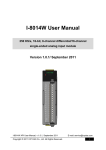
Magic Scan Type:
Type 1: standard
Each Sample clock only samples a single.
Magic Scan Standard Mode
12
10
8
6
4
2
0
1
10 19 28 37 46 55 64 73 82 91 100 109 118 127 136 145 154 163 172
I-8014W user’s manual (V 1.0, Apr/2011) ---------------- 6
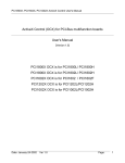
Type 2: virtual Sample and hold
Each sample clock will to sample all scan channels that have been set.
Magic Scan Sample & Hold
12
10
8
6
4
2
0
1
6 11 16 21 26 31 36 41 46 51 56 61 66 71 76 81 86 91 96 101 106 111 116
I-8014W user’s manual (V 1.0, Apr/2011) ---------------- 7
Analog Input
Input Channels
16-ch Single-ended/8-ch Differential
Input Range
+/- 10V, +/- 5V, +/- 2.5V, +/- 1.25V
-20mA ~ +20mA(Requires Optional
External 125 Ohm Resistor)
Resolution
16-bit
Sample Rate
Single Channel Polling Mode :250K S/s
FIFO
4K Words
Accuracy
0.05% of FSR +/- 1LSB
Scan Mode
Polling , Pacer (Magic Scan)
Scan Function
Magic Scan Type 1, Magic Scan Type 2
Overvoltage protection
+60 V~ -45 V
Input Impedance
20K,200K,20M(Jumper Select)
Intra-module Isolation, Field to Logic
2500 Vrms
LED Display
1 LED as Power Indicator
Power
Power Consumption
2.5W Max
Environment
Operating Temperature
-25 ~ 75°C
Storage Temperature
-30 ~ 85°C
Humidity
5 to 95% RH, Non-condensing
Dimensions
30mm x 102mm x 115mm (W x L x H)
I-8014W user’s manual (V 1.0, Apr/2011) ---------------- 8
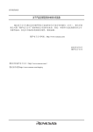
Internal I/O Structure
PIN Assignments
I-8014W user’s manual (V 1.0, Apr/2011) ---------------- 9
Wire Connection
I-8014W user’s manual (V 1.0, Apr/2011) ---------------- 10
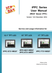
Jumper Select
Input Impedance Jumper
Secondary FPGA
Differential /
Single Ended Jumper
Primary FPGA
I-8014W user’s manual (V 1.0, Apr/2011) ---------------- 11
2. I-8014W API for Linux
Please refer to following steps to start I-8014W:
➊ Install SDK of Linux controller first if user never install.
➋ Open and modify I-8014W source code if necessary.
➌ Start ‘LinPAC-8000 Build Environment’ to compile your program by clicking on
‘Start Æ ICPDAS Æ LinPAC-8000 SDK Æ LinPAC-8000 Build Environment’
➍ Compile with linking the library—libi8k.a. (Compile *.c to *.exe)
I-8014W user’s manual (V 1.0, Apr/2011) ---------------- 12
➎ Transfer *.exe to Linux controller
Open a “DOS Command Prompt” or FTP software for transferring files.
➏
Change access permissions of file, and execute a file.
I-8014W user’s manual (V 1.0, Apr/2011) ---------------- 13
2.1 i8014W_Init
This function can initial the I-8014W and can check the hardware ID, if return 0
for input slot index, it means the ID of this slot index is I-8014W, if return -1, it means
there is no I-8014W for this slot index .
Syntax
[C]
short i814W_Init ( int slot );
Parameters
Slot
1~8
Return Values
Please refer to Error Code Table.
Note
Application program has to call i-8014W_Init(slot) first before you read the
Analog Input data, for this function will load the calibration parameters from EEPROM
at the same time.
Examples
int slot, err;
err=i8014W_Init(slot);
if(err==0) {
printf(“There is an I-8014W at slot %d\n”,slot);
}
else{
printf(“There is no I-8014W at slot %d\n”,slot);
}
I-8014W user’s manual (V 1.0, Apr/2011) ---------------- 14
2.2 i8014W_GetFirmwareVer_L1
This function gets the primary FPGA firmware version of I-8014W.
Syntax
[C]
short i8014W_GetFirmwareVer_L1(int slot);
Parameters
Slot
1~8
Return Values
The primary FPGA firmware version of I-8014W
Examples
short ver_L1=0;
slot=0;
ver_L1= i8014W_GetFirmwareVer_L1 (slot);
printf( "\nPrimary FPGA Version =: %04X",i8014W_GetFirmwareVer_L1(slot) );
I-8014W user’s manual (V 1.0, Apr/2011) ---------------- 15
2.3 i8014W_GetFirmwareVer_L2
This function gets the secondary FPGA firmware version of I-8014W.
Syntax
[C]
short i8014W_GetFirmwareVer_L2(int slot);
Parameters
Slot
1~8
Return Values
The secondary FPGA firmware version of I-8014W
Examples
short ver_L2=0;
slot=0;
ver_L2= i8014W_GetFirmwareVer_L2 (slot);
printf( "\nSecondary FPGA Version =%04X",i8014W_GetFirmwareVer_L2(slot) );
I-8014W user’s manual (V 1.0, Apr/2011) ---------------- 16
2.4 i8014W_GetLibVersion
This function gets the library version of i8014W.lib .
Syntax
[C]
short i8014W_GetLibVersion();
Parameter
None
Return Values
The library version of i8014W.lib
Examples
short version;
version = i8014W_GetLibVersion();
printf("\nLibrary Version =: %04X",i8014W_GetLibVersion());
I-8014W user’s manual (V 1.0, Apr/2011) ---------------- 17
2.5 i8014W_GetLibDate
This function gets the library built date of i8014W.lib.
Syntax
[C]
void i8014W_GetLibDate(char *LibDate);
Parameters
LibDate the string buffer of library built date
Return Values
The library built date of i8014W.lib
Examples
char libDate [32];
i8014W_GetLibDate(libDate);
Print("\nBuild Date =: %s",libDate);
I-8014W user’s manual (V 1.0, Apr/2011) ---------------- 18
2.6 i8014W_GetSingleEndJumper
To get the input signal mode of I-8014W.I-8014W can select input signal mode
via the selected jumper.
If jumper selects “Differential”, it can have maximum 8 channels available.
If jumper selects “Single Ended”, it can have maximum 16 channels available.
Syntax
[C]
short i8014W_GetSingleEndJumper(int slot);
Parameters
Slot
1~8
Return Values
The primary FPGA firmware version of I-8014W
0: Differential Mode
1: Single Ended Mode
Examples
int slot=1;
short jumper=0, maxCh=0;
jumper=i8014W_GetSingleEndJumper(slot);
if(jumper) {
maxCh=16;
printf("i8014W Input Mode=Single-End\n");
} else{
maxCh=8;
printf("i8014W Input Mode=Differential\n");
}
I-8014W user’s manual (V 1.0, Apr/2011) ---------------- 19
2.7 i8014W_SelectedImpedancy
I-8014W can have three types of input impedance resistors:
2M, 200K (Default jumper location) and 20K ohm.
I-8014W shipment with two sets of calibration parameters for each input range.
Default calibration parameters are for 2M and 200K ohm, they use the same
calibration parameters. Use this function can change calibration parameters for
different impedance resistor.
After change different impedance resistor calibration parameters, it can use
i8014W_ReadGainOffset function to check the new Gain and Offset value.
Syntax
[C]
void i8014W_SelectedImpedency(int slot,int resistorType);
Parameters
Slot
1~8
registorType
0 : 200K and 2M ohm (Default)
1 : 20K ohm
Return Values
None
Examples
int slot=0;
int resistorType =1; // 0 : 200K and 2M ohm
// 1 : 20K ohm
i8014W_ SelectedImpedency (slot, resistorType);
I-8014W user’s manual (V 1.0, Apr/2011) ---------------- 20
2.8 i8014W_ReadGainOffset
To get the calibrated gain and offset parameters for each input range. I-8014W
can have five types of input range:
0 : "+/-10V", 1: "+/-5V", 2: "+/-2.5V", 3: "+/-1.25V", 4: "+/-20mA"
Syntax
[C]
void i8014W_ ReadGainOffset( int slot, int gain, unsigned short* gainValue,
short* offsetValue );
Parameters
Slot
1~8
gain
0~4
*gainValue: the calibrated gain value loaded from EEPROM.
*offsetValue: the calibrated offset value loaded from EEPROM.
Return Values
None
Examples
int slot=1;
unsigned short gVal=0;
short oVal=0;
i8014W_ReadGainOffset(slot,gain,&gVal,&oVal);
printf("\nThe Gain and Offset for Calibration is Gain=%u; Offset=%d",gVal,oVal) ;
I-8014W user’s manual (V 1.0, Apr/2011) ---------------- 21
2.9 i8014W_ReadAI
To get calibrated float format analog input value from I-8014W.
Syntax
[C]
short i8014W_ReadAI(int slot, int ch, int gain, float* fVal);
Parameters
Slot
1~8
ch
0 ~ 8: differential
0 ~ 16: single-ended
gain
0~4
*fVal
calibrated float format analog input data
Return Values
Please refer to Error Code Table.
Examples
int slot,ch,gain;
float fVal=0.0;
slot = 1;
gain = 0; // "+/-10V"
for(ch=0;ch<8;ch++) // differential
{
i8014W_ReadAI( slot, ch, gain, & fVal);
printf("\n[%02d]= [ %05.4f ]", ch, fVal);
}
I-8014W user’s manual (V 1.0, Apr/2011) ---------------- 22
2.10 i8014W_ReadAIHex
To get calibrated float format analog input value from I-8014W.
Syntax
[C]
short i8014W_ReadAIHex(int slot, int ch, int gain, short* hVal);
Parameters
Slot
1~8
ch
0 ~ 8: differential
0 ~ 16: single-ended
gain
0~4
*hVal
calibrated hex format analog input data
Return Values
Please refer to Error Code Table.
Examples
int slot,ch,gain;
short hVal=0.0;
slot = 1;
gain = 0; // "+/-10V"
for(ch=0;ch<8;ch++)
{
i8014W_ReadAIHex( slot, ch, gain, & hVal);
printf("\n[%02d]= [ %04X ] ",ch,,hVal);
}
I-8014W user’s manual (V 1.0, Apr/2011) ---------------- 23
2.11 i8014W_ConfigMagicScan
This function is the most important for I-8014W to operate the Magic Scan.
Before using the Magic Scan, application must be well define the parameters for
Magic Scan.
Syntax
[C]
float i8014W_ConfigMagicScan
(
int slot,
int chArr[],
int gainArr[],
int scanChCount,
float sampleRate,
int scanMode,
int triggerSource,
int triggerState
);
Parameters
Slot
1~8
chArr[]
Sampled channel array, it can be have maximum 16 channel counts.
gainArr[]
Input range (gain 0 ~ 4) for each channel.
scanChCount
Total channel counts that Magic Scan will operate.
sampleRate
1 ~ 250KHz
scanMode
1 => Standard Mode;
2 => Sample and Hold
triggerSource
0 => Software Trigger;
1 => Internal Interrupt Signal Trigger;
2 => External Input Signal Trigger.
I-8014W user’s manual (V 1.0, Apr/2011) ---------------- 24
triggerState
0 => When external input signal level is high to activate the trigger.
1 => When external input signal level is low to activate the trigger.
Return Values
Real sample rate that I-8014W can acceptable.
Examples
int slot= 1, chArr[16], gainArr[16], scanChCount;
float sampleRate,realsampleRate;
int scanMode, triggerSource, triggerState;
chArr[0]=0; // element 0 assigned channel 0
chArr[1]=1;
…
chArr[15]=15; // element 15 assigned channel 15
gainArr[0]=0; // element 0 assigned Input range 0
gainArr[1]=1; // element 1 assigned Input range 1
…
gainArr[15]=4; // element 15 assigned Input range 4
scanChCount=1; //only sample chArr[0] (channel 0 )
sampleRate=25000.0; //set Sample rate 25 KHz
scanMode=1; // use M1 standard mode
triggerSource=1; // use internal interrupt signal Mode
triggerState=0;
realsampleRate = i8014W_ConfigMagicScan(slotIndex, chArr, gainArr,
scanChCount, sampleRate, scanMode,triggerSource,triggerState);
printf ("Set Sample Rate = %6.3f Real Sample Rate = %6.3f \n",sampleRate,
realsampleRate);
i804W_StartMagicScan (slot);
…
i8014W_ReadFIFO();
// Detail reviews i8014W_ReadFIFO section
I-8014W user’s manual (V 1.0, Apr/2011) ---------------- 25
2.12 i8014W_StartMagicScan
To start Magic Scan function and module will start to save data to FIFO (If
i8014W_ConfigMagicScan use external trigger signal mode, module will not start to
save data. It will start to save data when the signal is active)
Syntax
[C]
short i804W_StartMagicScan (int slot);
Parameters
Slot
1~8
Return Values
Please refer to Error Code Table.
Examples
int slot;
slot = 1;
i804W_StartMagicScan (slot);
I-8014W user’s manual (V 1.0, Apr/2011) ---------------- 26
2.13 i8014W_StopMagicScan
To stop Magic Scan function and stop saving data to FIFO.
Syntax
[C]
short i804W_StopMagicScan (int slot);
Parameters
Slot
1~8
Return Values
Please refer to Error Code Table.
Examples
int slot;
slot = 1;
i804W_StopMagicScan (slot);
//Detail reviews i804W_ReadFifo section
I-8014W user’s manual (V 1.0, Apr/2011) ---------------- 27
2.14 i8014W_ReadFIFO
This function is used to read data from FIFO and how many data in the FIFO.
Syntax
[C]
short i804W_ReadFifo
(
int slot,
short hexData[],
short readCount,
short* dataCountFromFIFO
);
Parameters
Slot
1~8
hexData []
Read hex format analog input data array from FIFO
readCount
How many counters of date will we want to read from FIFO
* dataCountFromFIFO
How many counters of date was read from FIFO
Return Values
Please refer to Error Code Table.
I-8014W user’s manual (V 1.0, Apr/2011) ---------------- 28
Examples
int slot;
short hexData[8192];
long readCnt=0;
short totalScaned=0;
short TargetCnt=1000;
slot = 1;
i8014W_ReadFIFO(slot,hexData+totalScaned, TargetCnt-totalScaned,&readCnt);
if(readCnt>0)
totalScaned+=readCnt;
if(readCnt==MAX_FIFO || totalScaned>=TargetCnt)
{
printf("\nEnd %d\n", readCnt);
i8014W_StopMagicScan(slot);
i8014W_UnLockFIFO(slot);
ShowAI_2(); //Show AI value that read from FIFO
i8014W_ClearFIFO(slot);
}
I-8014W user’s manual (V 1.0, Apr/2011) ---------------- 29
2.15 i8014W_UnLockFIFO
This function is used to unlock the FIFO. (When FIFO is overflow, it will be
locked and filled. It needs to unlock and clear the FIFO every time before starting next
magic scan)
Syntax
[C]
void i804W_UnLockFIFO (int slot);
Parameters
Slot
1~8
Return Values
Please refer to Error Code Table.
Examples
int slot;
slot = 1;
i804W_UnLockFIFO (slot);
I-8014W user’s manual (V 1.0, Apr/2011) ---------------- 30
2.16 i8014W_ClearFIFO
This function is used to clear data in the FIFO. (When FIFO is overflow, it will be
locked and filled. It needs to unlock and clear the FIFO every time before starting next
magic scan)
Syntax
[C]
void i804W_ClearFIFO (int slot);
Parameters
Slot
1~8
Return Values
Please refer to Error Code Table.
Examples
int slot;
slot = 1;
i804W_ClearFIFO (slot);
I-8014W user’s manual (V 1.0, Apr/2011) ---------------- 31
2.17 i8014W_CalibrateData
This function is used to show calibrated analog data. When we use Magic scan
to read data from FIFO, the analog data is not calibrated. We can use following
function to get the calibrated data.
Syntax
[C]
void i8014W_CalibrateData (int slot, int iGain,short dataFromFIFO,
float* calibratedAI);
Parameters
Slot
1~8
Gain
0~3
dataFormFIFO
Read hex format analog input data from FIFO
*calibratedAI
calibrated float format analog input data
Return Values
Please refer to Error Code Table.
Examples
int slot=1, i, readCnt=0, gain=0; // "+/-10V"
short hexData[8192], totalScaned=0, TargetCnt=1000;
i8014W_ReadFIFO(slot, hexData+totalScaned, TargetCnt-totalScaned,&readCnt);
if(readCnt>0)
for(i=0; i<100; i++)
{
i8014W_CalibrateData(slot, gain, dataFormFIFO ,&calibratedAI);
printf("i=%d: F[%f]\t", i, calibratedAI);
}
I-8014W user’s manual (V 1.0, Apr/2011) ---------------- 32
2.18 i8014W_CalibrateDataHex
This function is used to show calibrated analog data by Hex. When we use Magic
scan to read data from FIFO, the analog data is not calibrated. We can use following
function to get the calibrated data.
Syntax
[C]
void i8014W_CalibrateData (int slot, int iGain,short dataFromFIFO,
float* calibratedAI);
Parameters
Slot
1~8
Gain
0~3
dataFormFIFO
Read hex format analog input data from FIFO
*calibratedAI
calibrated float format analog input data
Return Values
Please refer to Error Code Table.
Examples
int slot=1, i, readCnt=0, gain=0; // "+/-10V"
short hexData[8192], totalScaned=0, TargetCnt=1000;
i8014W_ReadFIFO(slot, hexData+totalScaned, TargetCnt-totalScaned,&readCnt);
if(readCnt>0)
for(i =0; i<100; i++)
{
i8014W_CalibrateDataHex(slot, gain, dataFormFIFO ,&calibratedAI);
printf("i=%d: F[%f]\t", i, calibratedAI); }
I-8014W user’s manual (V 1.0, Apr/2011) ---------------- 33
3. Error Code for I-8014W
Error Code Table:
Error Code
Explanation
0
NoError
-1
ID_ERROR
-2
SLOT_ERROR
-3
CHANNEL_ERROR
-4
GAIN_ERROR
-5
INT_MODE_ERROR
-6
NOT_SUPPORT_ERROR
I-8014W user’s manual (V 1.0, Apr/2011) ---------------- 34