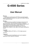
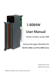
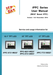
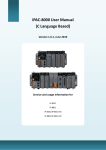
1
I-8014W User Manual
250 KS/s, 16-bit, 8-channel differential/16-channel
single-ended analog input module
Version 1.0.1/ September 2011
I-8014W API User Manual, v 1.0.1, September 2011
Copyright © 2011 ICP DAS Co., Ltd. All Rights Reserved.
E-mail: [email protected]
1
Warranty
All products manufactured by ICP DAS are under warranty
regarding defective materials for a period of one year, beginning
from the date of delivery to the original purchaser.
Warning
ICP DAS assumes no liability for any damage resulting from the
use of this product. ICP DAS reserves the right to change this
manual at any time without notice. The information furnished by
ICP DAS is believed to be accurate and reliable. However, no
responsibility is assumed by ICP DAS for its use, not for any
infringements of patents or other rights of third parties resulting
from its use.
Copyright
Copyright @ 2011 by ICP DAS Co., Ltd. All rights are reserved.
Trademark
The names used for identification only may be registered
trademarks of their respective companies.
Contact US
If you have any problem, please feel free to contact us.
You can count on us for quick response.
Email: [email protected]
I-8014W API User Manual, v 1.0.1, September 2011
Copyright © 2011 ICP DAS Co., Ltd. All Rights Reserved.
E-mail: [email protected]
2
Table of Contents
Table of Contents .......................................................................3
Preface.........................................................................................5
Hardware .....................................................................................6
Specifications
6
Pin Assignments
7
Jumper setting
8
Wire Connection
10
Block Diagram
11
Demo Programs Location
12
Quick Start ................................................................................14
On MiniOS7 platform controller............................................................14
Getting Started Guide
14
Calibration
17
On Windows platform controller ..........................................................26
Getting Started Guide
26
Calibration
28
Magic Scan................................................................................35
Magic Scan Mode...................................................................................36
Standard mode
37
Virtual Sample and hold mode
38
Trigger method.......................................................................................39
Software trigger method
39
Internal hardware trigger method
40
External hardware trigger method
41
FIFO.........................................................................................................42
Magic Scan Procedure ..........................................................................43
Magic Scan Example .............................................................................44
I-8014W API User Manual, v 1.0.1, September 2011
Copyright © 2011 ICP DAS Co., Ltd. All Rights Reserved.
E-mail: [email protected]
3
Magic.exe
44
Mag_ISR.exe
50
Case Example
51
API..............................................................................................53
Function list
54
Error code list
55
i8014W_Init
56
i8014W_GetFirmwareVer_L1
58
i8014W_GetFirmwareVer_L2
59
i8014W_GetLibVersion
60
i8014W_GetLibDate
61
i8014W_GetSingleEndJumper
62
i8014W_ReadGainOffset
64
i8014W_ReadAI
66
i8014W_ReadAIHex
68
i8014W_ConfigMagicScan
70
i8014W_StartMagicScan
73
i8014W_StopMagicScan
74
i8014W_ReadFIFO
75
i8014W_CalibrateData
77
i8014W_CalibrateDataHex
79
i8014W_UnLockFIFO
81
i8014W_ClearFIFO
82
i8014W_InstallMagicScanISR
83
i8014W_UnInstallMagicScanISR
86
i8014W_ClearInt
87
Troubleshooting .......................................................................88
How to verify the AI function on WinCE or WES unit?
88
Service-request requirement
92
Why does the data read from I-8014W seem unstable?
92
How to solve FIFO LATCHED error (-6)?
93
I-8014W API User Manual, v 1.0.1, September 2011
Copyright © 2011 ICP DAS Co., Ltd. All Rights Reserved.
E-mail: [email protected]
4
Preface
The I-8014W is a 16-bit resolution, high speed isolated analog input module providing
16 single-ended or 8 differential analog input channels. Besides basic usage
knowledge and SDK interface, this manual intends to introduce the Magic Scan
function of I-8014W for scanning multi-channel system.
This manual contains
h
Chapter 1, “Hardware” – Provides hardware information such as specifications,
jumper setting note and wiring.
h
Chapter 2, “Quick Start” – Provides how to start an overview demo programs
location, Getting Started Guide, and calibration process.
h
Chapter 3, “Magic Scan” – Introduces the parameters in Magic Scan function,
programming procedure, and demo programs.
h
Chapter 4, “API” – Describes the diversity of naming rule for MiniOS7 and
Windows platforms and functions provided in I-8014W library.
h
Chapter 5, “Troubleshooting” – Provides some techniques for troubleshooting the
problems faced.
I-8014W API User Manual, v 1.0.1, September 2011
Copyright © 2011 ICP DAS Co., Ltd. All Rights Reserved.
E-mail: [email protected]
5
Hardware
Specifications
Input Range
+/- 10 V, +/- 5 V, +/- 2.5 V, +/- 1.25 V
-20 mA ~ +20 mA (Requires Optional External
125 Ohm Resistor)
Resolution
16 bits
Sampling Rate
Single Channel, Polling Mode :250K S/s
FIFO
4k sample (8 k bytes)
Accuracy
0.05 % of FSR +/- 1 LSB
Input Mode
Polling, Pacer (Magic Scan)
Magic Scan Mode
Mode1: standard mode
Mode2: virtual sample and hold
Overvoltage Protection
+60 V ~ -45 V
Input Impedance
20 k, 200 k, 20 M (Jumper Select)
Intra-module Isolation, Field
to Logic
2500 Vrms
LED Power Indicator
Yes
Power Consumption
2.5 W Max
Operating Temperature
-25 ~ +75 °C
Storage Temperature
-30 ~ +85 °C
Humidity
5 to 95 % RH, Non-condensing
Dimensions (W x L x H)
30 mm x 102 mm x 115 mm
I-8014W API User Manual, v 1.0.1, September 2011
Copyright © 2011 ICP DAS Co., Ltd. All Rights Reserved.
E-mail: [email protected]
6
Pin Assignments
I-8014W API User Manual, v1.0.1, June 2011
Copyright © 2011 ICP DAS Co., Ltd. All Rights Reserved. E-mail: [email protected]
7
Jumper setting
Secondary
FPGA
Primary
FPGA
Differential / Single Ended select jumper
Input impedance select jumper
I-8014W API User Manual, v 1.0.1, September 2011
Copyright © 2011 ICP DAS Co., Ltd. All Rights Reserved.
E-mail: [email protected]
8
Input impedance adjustment
The I-8014W provides three input impedances such as 20k, 200k (default setting)
and 20M Ohm to meet system requirement. For most of cases, 200k is good enough.
Every time when the input impedance is changed on a calibrated module, it is
necessary to calibrate the module again, refer to Calibration, page17, if you are using
I-8000 or iPAC-8000 (MiniOS7 platform controller); if you use WinCE or WES
platform unit, refer to page 28 for the calibration process.
I-8014W API User Manual, v 1.0.1, September 2011
Copyright © 2011 ICP DAS Co., Ltd. All Rights Reserved.
E-mail: [email protected]
9
Wire Connection
Tips & Warnings
It is recommended to connect the V - to AGND (system ground)
when measuring differential voltage inputs as the figure shows
below:
While measuring current input, it is no use to enhance to accuracy.
I-8014W API User Manual, v1.0.1, June 2011
Copyright © 2011 ICP DAS Co., Ltd. All Rights Reserved. E-mail: [email protected]
10
Block Diagram
I-8014W API User Manual, v 1.0.1, September 2011
Copyright © 2011 ICP DAS Co., Ltd. All Rights Reserved.
E-mail: [email protected]
11
Demo Programs Location
The following table lists the location of I-8014W demo programs for different platform
for verifying the functions of the I-8014W and reusing the source code if needed.
Platform
Location
For I-8000 on Web
Library
ftp://ftp.icpdas.com/pub/cd/8000cd/napdos/8000/841x881x/demo/li
b/
Demo
ftp://ftp.icpdas.com/pub/cd/8000cd/napdos/8000/841x881x/demo/i
o_in_slot/
For I-8000 on CD
Library
CD:\Napdos\8000\841x881x\demo\Lib
Demo
CD:\Napdos\8000\841x881x\demo\IO_in_Slot
For iPAC-8000 on Web
Library
ftp://ftp.icpdas.com/pub/cd/8000cd/napdos/ipac8000/demo/basic/i
p-84x1_ip-88x1/lib/
Demo
ftp://ftp.icpdas.com/pub/cd/8000cd/napdos/ipac8000/demo/basic/i
p-84x1_ip-88x1/io_in_slot/
For iPAC-8000 on CD
Library
CD:\Napdos\iPAC8000\Demo\Basic\iP-84x1_iP-88x1\Lib
Demo
CD:\Napdos\iPAC8000\Demo\Basic\iP-84x1_iP-88x1\IO_in_Slot
For Windows CE5 on Web
Library
ftp://ftp.icpdas.com/pub/cd/winpac/napdos/wp-8x4x_ce50/sdk/io_
modules/
Demo
ftp://ftp.icpdas.com/pub/cd/winpac/napdos/wp-8x4x_ce50/demo/wi
npac/evc/pac_io/local/ (eVC demo)
ftp://ftp.icpdas.com/pub/cd/winpac/napdos/wp-8x4x_ce50/demo/wi
npac/dotnet/c%23.net/pac_io/local/ (C# demo)
I-8014W API User Manual, v 1.0.1, September 2011
Copyright © 2011 ICP DAS Co., Ltd. All Rights Reserved.
E-mail: [email protected]
12
Platform
Location
For Windows CE5 on CD
Library
Demo
(eVC & C#)
CD:\napdos\wp-8x4x_ce50\sdk\IO_Modules
CD:\napdos\wp-8x4x_ce50\Demo\WinPAC\eVC\PAC_IO\Local
CD:\napdos\wp-8x4x_ce50\Demo\WinPAC\DOTNET\C#.NET\PAC
_IO\Local
For Windows CE6 on Web
XP-8000
-CE6
ftp://ftp.icpdas.com/pub/cd/xp-8000-ce6/sdk/special_io/
ftp://ftp.icpdas.com/pub/cd/xp-8000-ce6/demo/xpac/vc2008/io/loca
l/
ftp://ftp.icpdas.com/pub/cd/xp-8000-ce6/demo/xpac/c%23/io/local/
XP-8000
-Atom-CE6
ftp://ftp.icpdas.com/pub/cd/xpac-atom-ce6/sdk/special_io/
ftp://ftp.icpdas.com/pub/cd/xpac-atom-ce6/demo/xpac/vc2008/io/lo
cal/
ftp://ftp.icpdas.com/pub/cd/xpac-atom-ce6/demo/xpac/c%23/io/loc
al/
For Windows CE6 on CD
XP-8000
-CE6
CD:\SDK\Special_IO
CD:\Demo\XPAC\VC2008\IO\Local
CD:\Demo\XPAC\C#\IO\Local
XP-8000
-Atom-CE6
CD:\SDK\Special_IO
CD:\Demo\XPAC\VC2008\IO\Local
CD:\Demo\XPAC\C#\IO\Local
For Windows Embedded Standard on Web
XP-8000
ftp://ftp.icpdas.com/pub/cd/xp-8000/sdk/io/
ftp://ftp.icpdas.com/pub/cd/xp-8000/demo/specialized_io/
XP-8000
-Atom
ftp://ftp.icpdas.com/pub/cd/xpac-atom/sdk/io/
ftp://ftp.icpdas.com/pub/cd/xpac-atom/demo/specialized_io/
For Windows Embedded Standard on CD
XP-8000
CD:\SDK\IO
CD:\Demo\Specialized_IO
XP-8000
-Atom
CD:\SDK\IO
CD:\Demo\Specialized_IO
I-8014W API User Manual, v 1.0.1, September 2011
Copyright © 2011 ICP DAS Co., Ltd. All Rights Reserved.
E-mail: [email protected]
13
Quick Start
This section gives the getting started guide and calibration process for using I-8014W
on MiniOS7 and Windows platforms individually.
This section contains getting started guide and calibration process for using I-8014W:
h
On MiniOS7 platform controller, page 14 (i-8000 and iPAC-8000 unit)
h
On Windows platform controller, page 26 (WinCE and WES unit)
On MiniOS7 platform controller
This section contains
h
Getting Started Guide, page 14
h
Calibration, page 17
Getting Started Guide
The executable file AI_INFO.EXE in basic_info folder of I-8014W demo could be used
to get the basic information of the I-8014W and verify the AI read function. The basic
information includes:
●
Version number and published date of library.
●
FPGA version
●
The Single-ended/ differential jumper setting position
●
The gain and offset values for every input range
●
The data read on each channel
(See Demo Programs Location, page 12 , to get AI_INFO.EXE in I-8014W demo
program)
I-8014W API User Manual, v 1.0.1, September 2011
Copyright © 2011 ICP DAS Co., Ltd. All Rights Reserved.
E-mail: [email protected]
14
Step 1. Refer to Jumper setting, page 8, make sure the Differential / Single Ended
select jumper is in differential position.
Step 2. Connect your stable signal source (ex. a battery output) to I-8014W by
differential wiring as below.
Step 3. Connect the power supply to the unit, and connect the control unit and PC by
RS232 cable.
841X/881X
POWER SUPPLY
+10V~30VDC
CA0915
HOST COMPUTER
I-8014W API User Manual, v 1.0.1, September 2011
Copyright © 2011 ICP DAS Co., Ltd. All Rights Reserved.
E-mail: [email protected]
15
Step 4. Launch AI_INFO.EXE on PC, verify the basic information and AI read from
each channel as follows:
Tips & Warnings
Unused channel should be connected to GND to avoid floating.
Library and FPGA version information
Single-ended/ differential jumper position
Gain value is around 33000, when it is far
from 33000 means that the value is
incorrect.
Verify the AI data from each channel.
I-8014W API User Manual, v 1.0.1, September 2011
Copyright © 2011 ICP DAS Co., Ltd. All Rights Reserved.
E-mail: [email protected]
16
Calibration
Every one of I-8014W is factory calibrated and well verified. Usually, it is unnecessary
to calibrate the module, unless the input impedance is changed on a calibrated
module, or the accuracy is lost.
To calibrate the I-8014W, in addition to plugging the I-8014W in the slot of controller,
the following items are needed:
●
One stable calibration source such as 3 1/2 digit power supplier (or better) or a
battery output.
●
One 4 1/2 digit voltage meter (15-bit resolution or better)
●
Calibration Program: see page 12 to get the demo program located in I-8014W
demo program.
Tips & Warnings
1. An unstable calibration source will cause the calibration fault and
affect the data acquisition accuracy.
2. If you would like to calibrate ± 20 mA, select ± 2.5V instead, the
two types use the same gain and offset values.
3. The calibration program use channel 0 to accept calibration
source only.
This section contains:
h
To calibrate the I-8014W on i-8000 and iPAC-8000 unit, page 18
h
To verify the calibration, page 24
h
To recover default calibration settings, page25
I-8014W API User Manual, v 1.0.1, September 2011
Copyright © 2011 ICP DAS Co., Ltd. All Rights Reserved.
E-mail: [email protected]
17
To calibrate the I-8014W on i-8000 and iPAC-8000 unit
Step 1. Repeat from step1 to step3 in Quick Start (See page 14)
a. Wire the power to control unit and control unit to PC.
b. Set the Differential / Single Ended jumper in differential position and
wire the calibration source to channel 0 by differential wiring.
c. Connect the meter as the following figure shows.
d. Turn on the control unit.
Calibration Source
I-8014W API User Manual, v 1.0.1, September 2011
Copyright © 2011 ICP DAS Co., Ltd. All Rights Reserved.
E-mail: [email protected]
18
Step 2. Launch MiniOS7 Utility on PC, download the calibration program to the
control unit and run it.
The MiniOS7 Utility could be downloaded from the following web site. Select the
proper calibration program for your controller.
● MiniOS7 Utility: http://www.icpdas.com/download/minios7.htm
● 8014cal.exe: the calibration program for I-8000 unit, located at the same folder
as I-8014W demo programs. (See Demo Programs Location, page 12)
● iP_8014cal.exe: the calibration program for iP-8000 unit, located at the same
folder as I-8014W demo programs. (See Demo Programs Location, page 12)
a. Launch MiniOS7 Utility on
PC, choose connection →
New connection.
b. Select the COM port on PC connected to the control unit from the drop-down
list, configure the communication parameters as follows, and click OK.
I-8014W API User Manual, v 1.0.1, September 2011
Copyright © 2011 ICP DAS Co., Ltd. All Rights Reserved.
E-mail: [email protected]
19
c. Highlight the calibration program and click Upload.
d. Right-click the updated calibration file and choose Run
I-8014W API User Manual, v 1.0.1, September 2011
Copyright © 2011 ICP DAS Co., Ltd. All Rights Reserved.
E-mail: [email protected]
20
The calibration program in control unit runs and on PC the 7188xw.exe runs to
provide a command line interface.
Step 3. Calibrate the I-8014W.
a. Select an input type from 0 ~ 3.
I-8014W API User Manual, v 1.0.1, September 2011
Copyright © 2011 ICP DAS Co., Ltd. All Rights Reserved.
E-mail: [email protected]
21
b. Determine two values (points) in the range of the selected input type for
calibration process.
For example, after selecting 0 (-10V ~ +10V), we would like to use +8V and
-8V as the two calibration points.
c. Make calibration
source output one of
the two points (ex.
8V)
d. Enter the value read
by meter at the input
1st voltage prompt in
the console and
press Enter.
I-8014W API User Manual, v 1.0.1, September 2011
Copyright © 2011 ICP DAS Co., Ltd. All Rights Reserved.
E-mail: [email protected]
22
e. Make the calibration source output the other point - 8V.
f. Enter the value read by meter at the input 2nd voltage prompt and press Enter
The console displays new gain and offset values for this calibration as:
New Gain= 3xxxx, Offset= nnn, Save to EEPROM? (y/n):
g. Enter y and press Enter to accept the values and save to EEPROM
The calibration for -10V ~ +10V is complete.
I-8014W API User Manual, v 1.0.1, September 2011
Copyright © 2011 ICP DAS Co., Ltd. All Rights Reserved.
E-mail: [email protected]
23
To verify the calibration
Step1. Make the calibration source output a voltage to channel 0 of I-8014W.
For example, -2V,
Step2. In the same console of calibration program, enter t (Read calibrated AI value
of Ch0) and select the input type which is just calibrated (ex. 0, -10 V ~10V ).
Step3. Confirm the data read from channel 0.
I-8014W API User Manual, v 1.0.1, September 2011
Copyright © 2011 ICP DAS Co., Ltd. All Rights Reserved.
E-mail: [email protected]
24
To recover default calibration settings
For 200k Ohm (default setting) input impedance, the calibration program provides (r)
Recover default calibration settings function to recover the gain and offset values
to factory default.
I-8014W API User Manual, v 1.0.1, September 2011
Copyright © 2011 ICP DAS Co., Ltd. All Rights Reserved.
E-mail: [email protected]
25
On Windows platform controller
This section contains:
h
Getting Started Guide, page 26
h
Calibration, page 28
Getting Started Guide
The executable file pac_i8014W_BasicInfo.exe in BasicInfo folder of I-8014W demo
could be used to get the basic information of the I-8014W and verify the AI read
function. The basic information includes:
● Version number and published date of library.
● FPGA version
● The Single-ended/ differential jumper setting position
● The gain and offset values for every input range
● The data read on each channel
(See Demo Programs Location, page 12,
to get pac_i8014W_BasicInfo.exe in
I-8014W demo program)
Step1. Refer to Jumper setting, page 8,
make sure the Differential / Single Ended
select jumper is in differential position.
Step2. Connect your stable signal source
(ex. a battery output) to I-8014W
by differential wiring.
Step3. Plug the I-8014W into the slot of
I-8014W API User Manual, v 1.0.1, September 2011
Copyright © 2011 ICP DAS Co., Ltd. All Rights Reserved.
E-mail: [email protected]
26
control unit and turn on the controller.
Step4. Launch pac_i8014W_BasicInfo.exe on controller, and verify the basic
information and AI read from each channel as follows:
Tips & Warnings
Unused channel should be connected to GND to avoid floating.
Library and FPGA version information
Single-ended/ differential jumper position
Gain value is around 33000, when it
is far from 33000 means that the
value is incorrect.
Verify the AI data from each channel.
I-8014W API User Manual, v 1.0.1, September 2011
Copyright © 2011 ICP DAS Co., Ltd. All Rights Reserved.
E-mail: [email protected]
27
Calibration
Every one of I-8014W is factory calibrated and well verified. Usually, it is unnecessary
to calibrate the module, unless the input impedance is changed on a calibrated
module, or the accuracy is lost.
To calibrate the I-8014W, in addition to plugging the I-8014W in the slot of controller,
the following items are needed:
●
One stable calibration source such as 3 1/2 digit power supplier (or better) or a
battery output.
●
One 4 1/2 digit voltage meter (15-bit resolution or better)
●
Calibration Program: see page 12 to get the demo program located in I-8014W
demo program.
Tips & Warnings
1: An unstable calibration source will cause the calibration fault and
affect the data acquisition accuracy.
2: If you would like to calibrate ± 20 mA , select ± 2.5V instead, the
two types use the same gain and offset values..
3: The calibration program use channel 0 to accept calibration
source only.
This section contains:
h
To calibrate the I-8014W on WinCE and WES unit, page 29
h
To verify the calibration, page 33
h
To recover default calibration settings, page 34
I-8014W API User Manual, v 1.0.1, September 2011
Copyright © 2011 ICP DAS Co., Ltd. All Rights Reserved.
E-mail: [email protected]
28
To calibrate the I-8014W on WinCE and WES unit
Step1. Refer to Jumper setting, page 8,
make sure the Differential / Single
Ended select jumper is in differential
position.
Step2. Connect your calibration source to
channel 0 of I-8014W by differential
wiring.
Step3. Plug the I-8014W into the slot of
controller and turn on the controller.
Step4. Launch
pac_i8014W_Calibration.exe on controller.
(In the c# demos for I-8014W, see
Demo Programs Location, page 12
and 13)
Tips & Warnings
Only channel 0 is valid to perform calibration
I-8014W API User Manual, v 1.0.1, September 2011
Copyright © 2011 ICP DAS Co., Ltd. All Rights Reserved.
E-mail: [email protected]
29
Step5. Select the I-8014W slot number and input range from the drop-down list
located in the upper part of the window.
Step6. Determine two values (points) in the range of the selected input type for
calibration process.
For example, after selecting 0 (-10V ~ +10V), we would like to use +8V and
-8V as the two calibration points:
Step7. Make calibration source output one of the two points (ex. 8V)
I-8014W API User Manual, v 1.0.1, September 2011
Copyright © 2011 ICP DAS Co., Ltd. All Rights Reserved.
E-mail: [email protected]
30
Step8. Click the Step1. Set point 1 tab, enter the value read by meter (ex. 8.0), and
click Set as Calibration Point 1.
Step9. Make calibration source output the other value (ex. - 8V)
Step10. Click the Step2. Set point 2 tab, enter the value read by meter (ex. - 8.0),
and click Set as Calibration Point 2.
I-8014W API User Manual, v 1.0.1, September 2011
Copyright © 2011 ICP DAS Co., Ltd. All Rights Reserved.
E-mail: [email protected]
31
Step11. Click the Step3. apply settings tab, click Save new calibration settings.
The calibration for -10V ~ +10V is complete.
I-8014W API User Manual, v 1.0.1, September 2011
Copyright © 2011 ICP DAS Co., Ltd. All Rights Reserved.
E-mail: [email protected]
32
To verify the calibration
Step1. Make the calibration source output a voltage to channel 0 of I-8014W.
For example, -2V,
Step2. Click the Step1. Set point 1 tab, confirm the AI read back as following:
I-8014W API User Manual, v 1.0.1, September 2011
Copyright © 2011 ICP DAS Co., Ltd. All Rights Reserved.
E-mail: [email protected]
33
To recover default calibration settings
For 200k Ohm (default setting) input impedance, the calibration program provides
Recover default calibration settings function to recover the gain and offset values
to factory default:
Click the Step3. apply settings tab , and click the Recover default calibraion
setting button.
I-8014W API User Manual, v 1.0.1, September 2011
Copyright © 2011 ICP DAS Co., Ltd. All Rights Reserved.
E-mail: [email protected]
34
Magic Scan
This chapter provides the detail of Magic Scan, the key function designed on the
I-8014W for multi-channel high sampling rate analog data acquisition.
At the last part of this chapter, it introduces two demo programs for implementing
Magic Scan. Both the Magic Scan mode and trigger method could be selected in the
two programs, the only difference is that one transfers data by polling and the other
transfers data by interrupt.
This chapter contains:
h
Magic Scan modes, page 36
h
Trigger methods for the Magic Scan, page 39
h
Magic Scan Example, page 44,
the Magic Scan
-- introduces the two data transfer modes for
I-8014W API User Manual, v 1.0.1, September 2011
Copyright © 2011 ICP DAS Co., Ltd. All Rights Reserved.
E-mail: [email protected]
35
Magic Scan Mode
For multi-channel high speed data acquisition system, the I-8014W provides up to
250 kHz sampling rate and 4k sample FIFO to reduce the loading of CPU and
advance the performance of your system.
The following table describes the specification of Magic Scan:
Max.
channel
Sampling
rate
16
2Hz ~ 250
kHz
FIFO
Sampling
mode
4k
- standard
sample - virtual
sample
and hold
Trigger method
Transfer data
mode
-software
- polling
-internal
hardware
- interrupt
-external
hardware
This section describes the two Magic Scan modes in which the I-8014W might use:
h
Standard mode, page 37
h
Virtual sample and hold mode, page 38
I-8014W API User Manual, v 1.0.1, September 2011
Copyright © 2011 ICP DAS Co., Ltd. All Rights Reserved.
E-mail: [email protected]
36
Standard mode
It converts one data from one channel at every sampling occasion.
For example, if the Ch0, Ch1and Ch2 are configured into the scan function, and
sampling rate is set as 1 kHz, the time period between every sampling operation is 1
ms, and scan one cycle (from Ch0 to Ch1 to Ch2) needs 3ms as below:
I-8014W API User Manual, v 1.0.1, September 2011
Copyright © 2011 ICP DAS Co., Ltd. All Rights Reserved.
E-mail: [email protected]
37
Virtual sample and hold mode
Virtual sample and hold works like that the several channels set into the scan function
are sampled at the same time; actually, the sampling rate is 250 kHz , and the scan
cycle time is the period for the sampling rate you set into the Magic Scan.
For example, if you set the sampling rate as 1 kHz and configure Ch0, Ch1, and Ch2
into the scan function, the sampling rate for scanning Ch0 to Ch2 is 250 kHz, and the
frequency of scan cycle is 1 kHz, therefore, the time used between one scan cycle to
the next is 1 ms.
I-8014W API User Manual, v1.0.1, June 2011
Copyright © 2011 ICP DAS Co., Ltd. All Rights Reserved. E-mail: [email protected]
38
Trigger method
This section contains:
h
Software trigger method, page 39
h
Internal hardware trigger method, page 40
h
External hardware trigger method, page 41
Software trigger method
The API provides a trigger instruction to start Magic Scan. If you have two or more
modules, you need to configure the Magic Scan parameters to each module and
execute the Magic Scan instruction to the modules one by one.
Start Magic Scan from one module to next by software
instruction.
I-8014W API User Manual, v1.0.1, June 2011
Copyright © 2011 ICP DAS Co., Ltd. All Rights Reserved. E-mail: [email protected]
39
Internal hardware trigger method
If you would like to synchronously start the Magic Scan function on two or more
modules, you can set the trigger source as the internal hardware signal in program,
and the internal trigger signal will trigger the Magic Scan operation almost at the
same time for the several modules.
Trigger the Magic Scan for each module by internal
hardware signal.
I-8014W API User Manual, v1.0.1, June 2011
Copyright © 2011 ICP DAS Co., Ltd. All Rights Reserved. E-mail: [email protected]
40
External hardware trigger method
The Magic Scan also accepts external trigger source from the first two terminals, and
with this trigger method, you can set it as rising edge triggered or falling edge
triggered. After setting the external trigger source, triggering condition and starting the
Magic Scan in program, the I-8014W will wait unless it receive the external form Trig+
and Trig- terminals and then start the Magic Scan.
I-8014W API User Manual, v1.0.1, June 2011
Copyright © 2011 ICP DAS Co., Ltd. All Rights Reserved. E-mail: [email protected]
41
FIFO
The I-8014W is equipped with a 4 k sample of FIFO which may store 4096 samples of
data from Magic Scan to guarantee no data loss. The acquisition data is saved into
the FIFO one by one in the scan process. We have to read back data from the FIFO
in time to avoid FIFO filled; if the FIFO is filled, the data can not be saved again until a
FIFO clear command is executed. On the other hand, if we read data from FIFO too
frequently, it will waste CPU time and reduce the performance. To get the best
balance, we provide two modes to transfer data from FIFO, one is by polling and the
other is by interrupt.
I-8014W API User Manual, v1.0.1, June 2011
Copyright © 2011 ICP DAS Co., Ltd. All Rights Reserved. E-mail: [email protected]
42
Magic Scan Procedure
The program procedure is illustrated as below:
Initialize the module
Configure Magic Scan parameters
- Scan channel order (16 channels max.)
- Input range per channel
- Total sampling count
- Sampling rate (2~ 250 kHz)
- Scan mode
1 = standard mode
2 = virtual sample and hold mode
- Trigger method
0 = software trigger
1 = internal hardware trigger
2 = external hardware trigger
- External hardware trigger condition
0 = rising edge trigger
1 = falling edge trigger
Start Magic Scan
Convert hexadecimal data to floating
point
Read data from FIFO
till all data is obtained.
Physical data
Stop Magic Scan
I-8014W API User Manual, v1.0.1, June 2011
Copyright © 2011 ICP DAS Co., Ltd. All Rights Reserved. E-mail: [email protected]
43
Magic Scan Example
This section describes two Magic Scan demo programs that use different data
transfer modes. (See Demo Programs Location, page 12, to get the demo program
for your controller)
h
Magic.exe, page 44 – transfer data by polling
h
Mag_ISR.exe, page 50 – transfer data by interrupt
Magic.exe
This section describes the parameters that should be set in Magic.exe, and separates
the description for MiniOS7 and Windows platforms.
This section contains:
h
The demo program on MiniOS7 , page 45
h
The demo program on Windows platform, page 47
I-8014W API User Manual, v1.0.1, June 2011
Copyright © 2011 ICP DAS Co., Ltd. All Rights Reserved. E-mail: [email protected]
44
The demo program on MiniOS7
The following figure shows the interface and parameters that should be set in
Magic.exe on MiniOS7.
Step1. Input total scan
channel count.
(Form 1 to 16)
Step2. Set channel number and
input range for the channel.
The order of channel number
inputted determines the scan
order.
Step3. Input sampling rate.
Step4. Input the scan mode.
Step5. Select the trigger
method.
.
Step6. Set the trigger
condition if external trigger
is selected in stap5.
After complete setting of the Magic Scan parameters, press any key to start Magic
Scan as below:
The used parameters
list
I-8014W API User Manual, v1.0.1, June 2011
Copyright © 2011 ICP DAS Co., Ltd. All Rights Reserved. E-mail: [email protected]
45
If scan mode is set as standard mode, the total spend time equals [1000] multiplied by
[sampling period]. (1000 is the total sample count defined in demo program)
Check the total spend time.
I-8014W API User Manual, v1.0.1, June 2011
Copyright © 2011 ICP DAS Co., Ltd. All Rights Reserved. E-mail: [email protected]
46
The demo program on Windows platform
The following figure shows the interface and parameters need be set in Magic.exe on
Windows platform.
Step1. Select slot and input scan channel count. (From 1 to 16)
Step2. Select trigger source and input sampling rate.
If external trigger source is selected, select trigger state.
Step3. Select scan mode.
Step4. Select the channel scan order and
input type for each channel.
Step5: Press the “Setting” button.
Step6. Click the “Start Magic Scan” tag, and press Start Magic Scan.
The data and scan order shows in the right pane.
I-8014W API User Manual, v1.0.1, June 2011
Copyright © 2011 ICP DAS Co., Ltd. All Rights Reserved. E-mail: [email protected]
47
Result of standard scan mode
Click the Start Magic Scan tag, when the sampling rate is set as 200 Hz, the
sampling period is 1/200 * 1000 = 5 ms. And spend time equals [total sample count]
multiplied by [sampling period].
In this demo, the spend time 5004 ms equals to about 1000 (total sample count
defined in code) times 5 (sampling period).
I-8014W API User Manual, v1.0.1, June 2011
Copyright © 2011 ICP DAS Co., Ltd. All Rights Reserved. E-mail: [email protected]
48
Result of virtual sample and hold mode
Click the Start Magic Scan tag. When the sampling rate is set as 200 Hz, the period
for one scan cycle is 1/200 * 1000 = 5 ms.
The number of scan cycle = [Total sample count] / [Total scan channel count].
In this demo, the spend time 1254 ms = (1000 / 4) * 5
(Spend time = [scan cycle number] * [scan cycle period])
The spend time can be used to verify the sampling rate on I-8014W.
I-8014W API User Manual, v1.0.1, June 2011
Copyright © 2011 ICP DAS Co., Ltd. All Rights Reserved. E-mail: [email protected]
49
Mag_ISR.exe
Mag_ISR.exe demonstrates how to transferring data by interrupt. By this way, the
Magic scan parameters settings are identical to those in Magic.exe; (see Magic Scan
Procedure, page 43 and Magic.exe, page 44) the only difference is that we have to
install interrupt service routine (ISR) before starting Magic Scan as:
i8014W_InstallMagicScanISR(slotIndex,Slot_ISR,triggerLevel);
i8014W_StartMagicScan(slotIndex);
The ISR installed will handle the task when interrupt signal is arisen from FIFO, and
parameter triggerLevel is for setting the interrupt condition as the follows:
triggerLevel
Data count
0
8
1
16
2
32
3
64
4
128
5
256
6
512
7
2048
If the data count in FIFO meets the condition that triggerLevel set, the interrupt signal
will be arisen, and the code in ISR installed will process. Please note that you need to
call clear interrupt function in ISR, otherwise the next interrupt signal will not be
serviced again.
Using interrupt to transfer data could save the CPU time used to polling and waiting
data from FIFO.
I-8014W API User Manual, v1.0.1, June 2011
Copyright © 2011 ICP DAS Co., Ltd. All Rights Reserved. E-mail: [email protected]
50
Case Example
The case requires:
1.
Measuring 4 differential signals ranged from -10 V to 10V.
2.
The sampling rate per channel is 200 Hz, and sampling time interval from one
channel to the next channel is less than 10μs.
3.
When 2000 samples of data collected every time, transfer the data through
Ethernet to data center or a remote data storage disk.
To meet the requirements:
Step1. Set the jumper on I-8014W as differential input mode.
Step2. Set input channel as ch0 ~ ch3, and input range of each channel as -10 ~ 10 V.
(Gain = 0)
Step3. Set sampling rate as 200, and scan mode as mode2: virtual sample and hold
mode. (With virtual sample and hold mode, and sampling time interval
between one channel to another channel is 4 μs.)
Step4. Collecting 2000 samples means collecting 500 samples per channel. (2000
divided by four channels) It needs 500 * (1/ 200 Hz) = 2500 ms.
Step5. If the system uses MiniOS7 platform, both converting data from hexadecimal
to floating and transferring data through Ethernet add CPU load. It is
recommended to transfer the hexadecimal data to PC client and then convert
them to floating data on PC.
I-8014W API User Manual, v1.0.1, June 2011
Copyright © 2011 ICP DAS Co., Ltd. All Rights Reserved. E-mail: [email protected]
51
If the system uses Windows platform, converting hexadecimal data to floating point
data would not affect the CPU load. You can convert data local and then transfer the
floating data through Ethernet.
Tips & Warnings
It is recommended to create several buffers to deal with the data
obtained from FIFO and reuse them in process as the figure below.
This allows the system has time to convert data, save and transfer
them.
Buffer 0
Buffer 1
2000 samples of
data collected
Buffer 2
2000 samples of
data collected
2000 samples of
data collected
Buffer 0
T0
T1
Buffer 1
Time
axis
T2
Transferring data
through Ethernet
Transferring data
through Ethernet
I-8014W API User Manual, v1.0.1, June 2011
Copyright © 2011 ICP DAS Co., Ltd. All Rights Reserved. E-mail: [email protected]
52
API
ICP DAS provides APIs, library and demo programs including source code for easy
integration I-8014W into the following platforms. The APIs and programming
procedure are similar on MiniOS7 and Windows platform, the only difference is the
prefix characters added to the name for the functions in library (APIs). “i8014W_” is
prefixed to the function name applied on MiniOS7 and Linux platform, and
“pac_i8014W_” is prefixed to the functions for Windows platform.
In this manual, we use the function name on MiniOS7 platform as example and the
title of the section for each function.
The following table describes the platforms and in which the product series included
and the different part of function name.
Platform
Windows CE5
Windows CE6
Windows Embedded
Standard (WES)
Product included
API prefix characters
WP-8000 series
WP-2000 series
“pac_i8014W_ “+ function name
XP-8000-CE6 series
XP-8000 series
“pac_i8014W_ “+ function name
I-8000 series
MiniOS7
iPAC-8000 series
“i8014W_”
+ function name
VP-2000 series
Linux
LinPAC-8000 series
“i8014W_” + function name
I-8014W API User Manual, v1.0.1, June 2011
Copyright © 2011 ICP DAS Co., Ltd. All Rights Reserved. E-mail: [email protected]
53
Function list
The following table lists the functions provided in 8014W.lib for MiniOS7 platform.
Function
Description
i8014W_Init
Initializes the driver and confirms hardware ID.
i8014W_GetFirmwareVer_L1
Gets the version number of the primary FPGA
firmware for troubleshooting.
i8014W_GetFirmwareVer_L2
Gets the version number of the secondary
FPGA firmware for troubleshooting.
i8014W_GetLibVersion
Gets the version number of 8014W.lib.
i8014W_GetLibDate
Gets the release date of 8014W.lib.
i8014W_GetSingleEndJumper
Gets the single-ended / differential jumper
position set on the I-8014W.
i8014W_ReadGainOffset
Obtains the gain and offset values for each
input type.
i8014W_ReadAI
Reads a floating point input from one specified
channel.
i8014W_ReadAIHex
Reads a hexadecimal input from one specified
channel.
i8014W_ConfigMagicScan
Configures all the parameters needed in Magic
Scan.
Starts Magic Scan, the data acquired will be
saved into FIFO
i8014W_StartMagicScan
If the external trigger source is selected, the
Magic Scan will wait after the function is called
until the trigger signal is arrived.
i8014W_StopMagicScan
Stops Magic Scan, it also stops save data into
FIFO.
i8014W_ReadFIFO
Reads a specified number of data from FIFO.
i8014W_CalibrateData
Calibrates the raw data read by Magic Scan
and converts to floating point value.
I-8014W API User Manual, v1.0.1, June 2011
Copyright © 2011 ICP DAS Co., Ltd. All Rights Reserved. E-mail: [email protected]
54
Function
Description
i8014W_CalibrateDataHex
Calibrates the raw data read by Magic Scan.
i8014W_UnLockFIFO
Unlocks FIFO when it is locked because the
data fills the FIFO. If the FIFO is locked,
UnlockFIFO and ClearFIFO commands need
be executed for the next scan.
i8014W_ClearFIFO
Clears FIFO after the UnlockFIFO function
executed.
i8014W_InstallMagicScanISR
Installs ISR for interrupt events form FIFO.
i8014W_UnInstallMagicScanI
SR
Uninstalls Magic Scan ISR.
i8014W_ClearInt
Clears interrupt status for waiting the next
interrupt event.
Error code list
Error code
Definition
Description
0
NoError
No error.
-1
ID_ERROR
Check module’s ID
-2
SLOT_ERROR
Slot index (0 ~ 7)
-3
CHANNEL_ERROR
Channel index (0 ~ 15)
-4
GAIN_ERROR
Gain (0 ~ 4)
-5
FIFO_EMPTY
No data in FIFO.
-6
FIFO_LATCHED
FIFO is full and be latched
-7
FIFO_OVERFLOW
FIFO is full
-8
TX_NOTREADY
Error between primary
secondary FPGA
FPGA
and
I-8014W API User Manual, v1.0.1, June 2011
Copyright © 2011 ICP DAS Co., Ltd. All Rights Reserved. E-mail: [email protected]
55
i8014W_Init
This function initializes the driver and confirms the hardware ID.
Prototype
For MiniOS7
short
i8014W_Init ( int slot );
For Windows (CE and WES)
short
pac_i8014W_Init( int slot );
Parameter
slot: 0 ~ 7
Return
0 = the module plugged in the slot is I-8014W.
-1 = there is no I-8014W module in this slot.
For other returned value, see Error code list, page 55.
Note
Before you start to run any function for I-8014W, the initial function need be
executed once for one I-8014W. If you have two or more I-8014W, you need call
the initial function for each I-8014W individual by passing the slot number that
the I-8014W plugged in.
I-8014W API User Manual, v1.0.1, June 2011
Copyright © 2011 ICP DAS Co., Ltd. All Rights Reserved. E-mail: [email protected]
56
Example
[C/C++]
int slotIndex,err;
err=i8014W_Init(slotIndex);
if(err==0)
{
Print(“There is an I-8014W at slot %d\n”,slotIndex);
}
else
{
Print(“There is no I-8014W at slot %d\n”,slotIndex);
}
I-8014W API User Manual, v1.0.1, June 2011
Copyright © 2011 ICP DAS Co., Ltd. All Rights Reserved. E-mail: [email protected]
57
i8014W_GetFirmwareVer_L1
This function gets the version number of the primary FPGA firmware. It is for
troubleshooting or recording only.
Prototype
For MiniOS7
short i8014W_GetFirmwareVer_L1(int slot);
For Windows (CE and WES)
short pac_i8014W_GetFirmwareVer_L1(int slot);
Parameter
slot: 0 ~ 7
Return
TheI-8014W version number of the primary FPGA firmware
Example
[C++]
short ver_L1=0, slot=0;
ver_L1= i8014W_GetFirmwareVer_L1 (slot);
Print( "\nPrimary FPGA Version =:
%04X",i8014W_GetFirmwareVer_L1(slot) );
I-8014W API User Manual, v1.0.1, June 2011
Copyright © 2011 ICP DAS Co., Ltd. All Rights Reserved. E-mail: [email protected]
58
i8014W_GetFirmwareVer_L2
This function gets the version number of the secondary FPGA firmware. It is for
troubleshooting or recording only.
Prototype
For MiniOS7
short i8014W_GetFirmwareVer_L2(int slot);
For Windows (CE and WES)
short pac_i8014W_GetFirmwareVer_L2(int slot);
Parameter
slot: 0 ~ 7
Return
The I-8014W version number of the secondary FPGA firmware
Example
[C++]
short ver_L2=0, slot=0;
ver_L2= i8014W_GetFirmwareVer_L2 (slot);
Print( "\nSecondary FPGA Version =:
%04X",i8014W_GetFirmwareVer_L2(slot) );
I-8014W API User Manual, v1.0.1, June 2011
Copyright © 2011 ICP DAS Co., Ltd. All Rights Reserved. E-mail: [email protected]
59
i8014W_GetLibVersion
This function gets the version number of 8014W.lib. It is for troubleshooting or
recording only.
Prototype
For MiniOS7
short i8014W_GetLibVersion(void);
For Windows (CE and WES)
short pac_i8014W_GetLibVersion(void);
Parameter
None
Return
The version number of 8014W.lib
Example
[C++]
short version;
version = i8014W_GetLibVersion();
Print("\nLibrary Version =: %04X",i8014W_GetLibVersion());
I-8014W API User Manual, v1.0.1, June 2011
Copyright © 2011 ICP DAS Co., Ltd. All Rights Reserved. E-mail: [email protected]
60
i8014W_GetLibDate
This function is used to get the release date of 8014W.lib.
Prototype
For MiniOS7
void i8014W_GetLibDate(char *LibDate);
For Windows (CE and WES)
void pac_i8014W_GetLibDate(char libDate[]);
Parameter
*LibDate: [Output] the release date of 8014W.lib
Return
None
Example
[C++]
char libDate [32];
i8014W_GetLibDate(libDate);
Print("\nBuild Date =: %s",libDate);
I-8014W API User Manual, v1.0.1, June 2011
Copyright © 2011 ICP DAS Co., Ltd. All Rights Reserved. E-mail: [email protected]
61
i8014W_GetSingleEndJumper
This function is used to get the single-ended / differential jumper position setting on
the I-8014W. If you want to use 8-channel differential input, the jumper needs to be
put in differential position; similarly, the jumper needs be put in single-ended position,
then the 16-channel single-ended input works correctly.
Prototype
For MiniOS7
short i8014W_GetSingleEndJumper(int slot);
For Windows (CE and WES)
short pac_i8014W_GetSingleEndJumper(int slot);
Parameter
slot: 0 ~ 7
Return
0: The jumper is in differential position
1: The jumper is in single-ended position
I-8014W API User Manual, v1.0.1, June 2011
Copyright © 2011 ICP DAS Co., Ltd. All Rights Reserved. E-mail: [email protected]
62
Example
[C++]
short jumper=0, maxCh=0;
jumper = i8014W_GetSingleEndJumper(slot);
if(jumper)
{
maxCh=16;
Print("i8014W Input Mode=Single-End\n\r");
}
else
{
maxCh=8;
Print("i8014W Input Mode=Differential\n\r");
}
I-8014W API User Manual, v1.0.1, June 2011
Copyright © 2011 ICP DAS Co., Ltd. All Rights Reserved. E-mail: [email protected]
63
i8014W_ReadGainOffset
This function is used to obtain the gain and offset values for each input type.
The input types are numbered as:
0: +/-10 V, 1: +/-5 V, 2: +/-2.5 V, 3: +/-1.25 V, 4: +/-20 mA
Prototype
For MiniOS7
void i8014W_ ReadGainOffset
(
int slot, int gain, unsigned short* gainValue, short* offsetValue
);
For Windows (CE and WES)
void pac_i8014W_ReadGainOffset
(
int slot,short gain,unsigned short* gainValue, short* offsetValue
);
Parameter
Slot: 0 ~ 7
Gain: specifies the input type (0 ~ 4).
0: +/-10 V, 1: +/-5 V, 2: +/-2.5 V, 3: +/-1.25 V, 4: +/-20 mA
*gainValue: [Output] gain value for the input range
*offsetValue: [Output] offset value for the input range
Return
None
I-8014W API User Manual, v1.0.1, June 2011
Copyright © 2011 ICP DAS Co., Ltd. All Rights Reserved. E-mail: [email protected]
64
Example
[C++]
unsigned short gVal=0;
short oVal=0;
i8014W_ReadGainOffset(slot,gain,&gVal,&oVal);
Print("\nThe Gain and Offset for Calibration is
Gain=%u; Offset=%d",gVal,oVal);
I-8014W API User Manual, v1.0.1, June 2011
Copyright © 2011 ICP DAS Co., Ltd. All Rights Reserved. E-mail: [email protected]
65
i8014W_ReadAI
This function is used to read a floating point input (calibrated) from one specified
channel.
Prototype
For MiniOS7
short i8014W_ReadAI( int slot, int ch, int gain, float* fVal );
For Windows (CE and WES)
short pac_i8014W_ReadAI( int slot, short ch, short gain, float* fVal );
Parameter
slot: 0 ~ 7
ch: 0 ~ 7 for differential input, or 0 ~ 15 for single-ended input
gain: 0 ~ 4, sets the input range:
0: +/-10 V, 1: +/-5 V, 2: +/-2.5 V, 3: +/-1.25 V, 4: +/-20 mA
*fVal: [Output] the floating-point data
Return
0 = No Error
For other returned value, see Error code list, page 55.
I-8014W API User Manual, v1.0.1, June 2011
Copyright © 2011 ICP DAS Co., Ltd. All Rights Reserved. E-mail: [email protected]
66
Example
[C++]
int slot,ch,gain;
float fVal=0.0;
slot = 0;
gain = 0; // "+/-10V"
for(ch=0;ch<8;ch++)
{
i8014W_ReadAI( slot, ch, gain, & fVal);
Print("\n[%02d]= [ %05.4f ]",ch,,fVal);
}
I-8014W API User Manual, v1.0.1, June 2011
Copyright © 2011 ICP DAS Co., Ltd. All Rights Reserved. E-mail: [email protected]
67
i8014W_ReadAIHex
This function is used to read a hexadecimal input (calibrated) from one specified
channel.
Prototype
For MiniOS7
short i8014W_ReadAIHex(int slot, int ch, int gain, short* hVal);
For Windows (CE and WES)
short pac_i8014W_ReadAIHex(int slot, short ch, short gain, short* hVal);
Parameter
slot: 0 ~ 7
ch: 0 ~ 7 for differential input, or 0 ~ 15 for single-ended input
gain: 0 ~ 4, sets the input type:
0: +/-10 V, 1: +/-5 V, 2: +/-2.5 V, 3: +/-1.25 V, 4: +/-20 mA
*hVal: [Output] the hexadecimal data
Return
0 = No Error
For other returned value, see Error code list, page 55.
I-8014W API User Manual, v1.0.1, June 2011
Copyright © 2011 ICP DAS Co., Ltd. All Rights Reserved. E-mail: [email protected]
68
Example
[C++]
int slot,ch,gain;
short hVal=0.0;
slot = 0;
gain = 0; // "+/-10V"
for(ch=0;ch<8;ch++)
{
i8014W_ReadAIHex( slot, ch, gain, & hVal);
Print("\n[%02d]= [ %04X ] ",ch,,hVal);
}
I-8014W API User Manual, v1.0.1, June 2011
Copyright © 2011 ICP DAS Co., Ltd. All Rights Reserved. E-mail: [email protected]
69
i8014W_ConfigMagicScan
This function is used to configure all the parameters needed in Magic Scan. It should
be called before the start Magic Scan instruction.
Prototype
For MiniOS7
void i8014W_ConfigMagicScan
(
int slot, int chArr[], int gainArr[], int scanChCount,
float sampleRate, int scanMode, int triggerSource,
int triggerState , float* realSampleRate
);
For Windows (CE and WES)
void pac_i8014W_ConfigMagicScan
(
int slot, short chArr[], short gainArr[], short scanChCount,
float sampleRate, short scanMode, short triggerSource,
short triggerState, float* realSampleRate
);
I-8014W API User Manual, v1.0.1, June 2011
Copyright © 2011 ICP DAS Co., Ltd. All Rights Reserved. E-mail: [email protected]
70
Parameter
slot: 0 ~ 7
chArr[]: an array for setting the channel to scan. The channel indices define the
scan order; the maximum channel number is 16.
gainArr[]: an array for setting the input type for the corresponding channel with
the same index in chArr[].
0: +/-10 V, 1: +/-5 V, 2: +/-2.5 V, 3: +/-1.25 V, 4: +/-20 mA
scanChCount: the count of channels which are added in chArr[]
sampleRate: total sampling rate,2 ~ 250 kHz
scanMode:
1: standard mode
2: virtual sample and hold mode
triggerSource:
0: software trigger
1: internal hardware trigger
2: external hardware trigger
triggerState:
0: rising edge trigger, it is valid only for external hardware trigger.
1: falling edge trigger, it is valid only for external hardware trigger.
*realSampleRate: [Output] the real sampling rate that the I-8014W used
Return
None
I-8014W API User Manual, v1.0.1, June 2011
Copyright © 2011 ICP DAS Co., Ltd. All Rights Reserved. E-mail: [email protected]
71
Example
[C++]
int slot, chArr[16], gainArr[16], scanChCount;
float sampleRate,realsampleRate;
int scanMode, triggerSource, triggerState;
slot = 0;
chArr[0]=0; // element 0 assigned channel 0
chArr[1]=1;
…
chArr[15]=15; // element 15 assigned channel 15
gainArr[0]=0; // element 0 assigned Input range 0
gainArr[1]=1; // element 1 assigned Input range 1
…
gainArr[15]=4; // element 15 assigned Input range 4
scanChCount=1; //only sample chArr[0] (channel 0 )
sampleRate=25000.0; //set Sample rate 25 KHz
scanMode=1; // use M1 standard mode
triggerSource=1; // use internal interrupt signal Mode
triggerState=0;
realsampleRate=i8014W_ConfigMagicScan(slotIndex,chArr,gainArr,scanCh
Count, sampleRate, scanMode,triggerSource,triggerState);
Print ("Set Sample Rate = %6.3f Real Sample Rate = %6.3f
\n",sampleRate, realsampleRate);
i804W_StartMagicScan(slot);
…
i8014W_ReadFIFO();
// Detail reviews i8014W_ReadFIFO section
I-8014W API User Manual, v1.0.1, June 2011
Copyright © 2011 ICP DAS Co., Ltd. All Rights Reserved. E-mail: [email protected]
72
i8014W_StartMagicScan
This function is used to start Magic Scan. While Magic scan starts, the data converted
is saved into FIFO immediately. When external hardware trigger is selected, the
I-8014W will wait after this function executed till it receives the trigger signal.
If you would like to start Magic Scan on more than one I-8014W simultaneously by
internal hardware trigger source, configure each module and execute StartMagicScan
function once, the argument slot could be any one slot number of those modules
plugged in.
Prototype
For MiniOS7
short i804W_StartMagicScan (int slot);
For Windows (CE and WES)
short pac_i8014W_StartMagicScan(int slot);;
Parameter
slot: 0 ~ 7
Return
0 = No Error
For other returned value, see Error code list, page 55.
Example
[C++]
int slot;
slot=0;
i804W_StartMagicScan(slot);
I-8014W API User Manual, v1.0.1, June 2011
Copyright © 2011 ICP DAS Co., Ltd. All Rights Reserved. E-mail: [email protected]
73
i8014W_StopMagicScan
This function is used to stop Magic Scan; the operation of saving data into FIFO is
also stopped because no data is converted again.
Prototype
For MiniOS7
short i804W_StopMagicScan (int slot);
For Windows (CE and WES)
short pac_i8014W_StopMagicScan(int slot);
Parameter
slot: 0 ~ 7
Return
0 = No Error
For other returned value, see Error code list, page 55.
Example
[C++]
int slot;
slot = 0;
i804W_StopMagicScan (slot);
//Detail reviews i804W_ReadFifo section
I-8014W API User Manual, v1.0.1, June 2011
Copyright © 2011 ICP DAS Co., Ltd. All Rights Reserved. E-mail: [email protected]
74
i8014W_ReadFIFO
This function is used to read data from FIFO after Magic Scan triggered. If the data in
FIFO is less than argument readCount, the function will read back all the data and
return immediately, you need to call this function again and reset argument hexData []
and readCount, till all the data required is obtained and then stop the Magic Scan.
Prototype
For MiniOS7
short i804W_ReadFIFO
(
int slot, short hexData[], short readCount,
short* dataCountFromFIFO
);
For Windows (CE and WES)
short pac_i8014W_ReadFIFO
(
int slot, short hexData[], short readCount,
short* dataCountFromFIFO
);
Parameter
Slot: 0 ~ 7
hexData []: the start address of data array to store data read back with
hexadecimal format
readCount: the count of data required
* dataCountFromFIFO: [Output] the count of data read back in this process.
Return
0 = No Error
For other returned value, see Error code list, page 55.
I-8014W API User Manual, v1.0.1, June 2011
Copyright © 2011 ICP DAS Co., Ltd. All Rights Reserved. E-mail: [email protected]
75
Example
[C++]
int slot;
short hexData[8192];
long readCnt=0;
short totalScaned=0;
short TargetCnt=1000;
slot = 0;
i8014W_ReadFIFO(slot,hexData+totalScaned,
TargetCnt-totalScaned,&readCnt);
if(readCnt>0)
totalScaned+=readCnt;
if(readCnt==MAX_FIFO || totalScaned>=TargetCnt)
{
i8014W_StopMagicScan(slot);
i8014W_UnLockFIFO(slot);
i8014W_ClearFIFO(slot);
}
I-8014W API User Manual, v1.0.1, June 2011
Copyright © 2011 ICP DAS Co., Ltd. All Rights Reserved. E-mail: [email protected]
76
i8014W_CalibrateData
This function is used to calibrate the raw data read in Magic Scan process and
convert to floating point value.
Prototype
For MiniOS7
void i8014W_CalibrateData
(
int slot, short iGain, short dataFromFIFO, float* calibratedAI
);
For Windows (CE and WES)
void pac_i8014W_CalibrateData
(
int slot, short iGain, short dataFromFIFO, float* calibratedAI
);
Parameter
Slot: 0 ~ 7
iGain: 0 ~ 4, sets the input type:
0: +/-10 V, 1: +/-5 V, 2: +/-2.5 V, 3: +/-1.25 V, 4: +/-20 mA
dataFromFIFO: the raw data read from FIFO
* calibratedAI : [Output] the floating point value.
Return
None
I-8014W API User Manual, v1.0.1, June 2011
Copyright © 2011 ICP DAS Co., Ltd. All Rights Reserved. E-mail: [email protected]
77
Example
[C++]
int slot;
int i;
float calibratedAI=0;
printf("Start to Print all data:\n\n\r");
for(i=0;i<totalScaned;i++);
{
slot = 0;
i8014W_CalibrateData (slotIndex,
gainArr[i %scanChCount],hexData[i], & calibratedAI);
printf("Arr[%d]=[%5.4f]\t",i%scanChCount,calibratedAI);
}
I-8014W API User Manual, v1.0.1, June 2011
Copyright © 2011 ICP DAS Co., Ltd. All Rights Reserved. E-mail: [email protected]
78
i8014W_CalibrateDataHex
This function is used to calibrate the raw data read in Magic Scan process.
Prototype
For MiniOS7
void i8014W_CalibrateDataHex
(
int slot, short iGain, short dataFromFIFO, short* calibratedAI
);
For Windows (CE and WES)
void pac_i8014W_ CalibrateDataHex
(
int slot, short iGain, short dataFromFIFO, short* calibratedAI
);
Parameter
Slot: 0 ~ 7
iGain: 0 ~ 4, sets the input type:
0: +/-10 V, 1: +/-5 V, 2: +/-2.5 V, 3: +/-1.25 V, 4: +/-20 mA
dataFromFIFO: the raw data read from FIFO
* calibratedAI : [Output] the calibrated hexadecimal value.
Return
None
I-8014W API User Manual, v1.0.1, June 2011
Copyright © 2011 ICP DAS Co., Ltd. All Rights Reserved. E-mail: [email protected]
79
Example
[C++]
int slot;
int i;
float calibratedAI=0;
printf("Start to Print all data:\n\n\r");
for(i=0;i<totalScaned;i++);
{
slot = 0;
i8014W_CalibrateDataHex (slotIndex,
gainArr[i %scanChCount],hexData[i], & calibratedAI);
printf("Arr[%d]=[%#x]\t",i%scanChCount,calibratedAI);
}
I-8014W API User Manual, v1.0.1, June 2011
Copyright © 2011 ICP DAS Co., Ltd. All Rights Reserved. E-mail: [email protected]
80
i8014W_UnLockFIFO
This function is used to unlock FIFO when the FIFO locked because of filled. Keep
the FIFO unlocked and cleared before the next Magic Scan starting.
Prototype
For MiniOS7
void i804W_UnLockFIFO (int slot);
For Windows (CE and WES)
void
pac_i8014W_UnLockFIFO(int slot);;
Parameter
slot: 0 ~ 7
Return
None
Example
[C++]
int slot;
slot = 0;
i804W_UnLockFIFO (slot);
//Detail reviews i804W_ReadFIFO section
I-8014W API User Manual, v1.0.1, June 2011
Copyright © 2011 ICP DAS Co., Ltd. All Rights Reserved. E-mail: [email protected]
81
i8014W_ClearFIFO
This function is used to clear FIFO after the UnlockFIFO function executed. Keep the
FIFO unlocked and cleared before the next Magic Scan starting.
Prototype
For MiniOS7
void i804W_ClearFIFO (int slot);
For Windows (CE and WES)
void pac_i8014W_ClearFIFO(int slot);;
Parameter
slot: 0 ~ 7
Return
None
Example
[C++]
int slot;
slot = 0;
i804W_ClearFIFO (slot);
//Detail reviews i804W_ReadFIFO section
I-8014W API User Manual, v1.0.1, June 2011
Copyright © 2011 ICP DAS Co., Ltd. All Rights Reserved. E-mail: [email protected]
82
i8014W_InstallMagicScanISR
This function is used to Install ISR for interrupt events form FIFO. Since the count of
data in FIFO is more than the definition of argument triggerLevel set (as table below),
the interrupt event occurs and the ISR executes to serve the event. In ISR, use
ReadFIFO to transfer data from FIFO and ClearInt to clear the interrupt status.
Prototype
For MiniOS7
short i804W_ InstallMagicScanISR
(
int slot, void (*isr)(int slot), int triggerLevel
);
For Windows (CE and WES)
short pac_i8014W_InstallMagicScanISR
(
int slot, void(*isr)(int slot), short triggerLevel
);
I-8014W API User Manual, v1.0.1, June 2011
Copyright © 2011 ICP DAS Co., Ltd. All Rights Reserved. E-mail: [email protected]
83
Parameter
slot: 0 ~ 7
*isr (int slot): the function pointer passed for ISR
triggerLevel: 0 ~ 7, it is used to set the interrupt trigger condition based on the
count of data in FIFO. If the argument is set more than 7, it will be
coerced to 7.
If the number of data in FIFO is more than the condition that triggerLevel
set, the interrupt will be triggered and the ISR executes to handle the
interrupt.
The following table lists the definition of triggerLevel:
triggerLevel
Data count
0
8
1
16
2
32
3
64
4
128
5
256
6
512
7
2048
Return
0 = No Error
For other returned value, see Error code list, page 55.
I-8014W API User Manual, v1.0.1, June 2011
Copyright © 2011 ICP DAS Co., Ltd. All Rights Reserved. E-mail: [email protected]
84
Example
[C++]
void main()
{
int slot,TrgLevel;
slot = 0;
TrgLevel=100;
i8014W_Install_MagicScanISR(slot,ISRFUN, TrgLevel);
i8014W_ConfigMagicScan(…);
// Detail reviews i8014W_ConfigMagicScan section
i8014W_StartMagicScan(slot);
…
while(1)
{
if(IntCnt>1)
{
i8014W_UnInstall_MagicScanISR(slot);
break;
}
}
…
}
void ISRFUN(int slot);
{
Int IntCnt=0;
IntCnt++;
ret=i8014W_ReadFIFO(slot, hexData+totalScaned,
TargetCnt-totalScaned,&readCnt);
if(readCnt >0)
{
totalScaned+=readCnt;
printCom1("TotalScaned= %d\n\r",totalScaned);
totalRead+=readCnt;
}
i8014W_ClearInt(slot);
}
I-8014W API User Manual, v1.0.1, June 2011
Copyright © 2011 ICP DAS Co., Ltd. All Rights Reserved. E-mail: [email protected]
85
i8014W_UnInstallMagicScanISR
This function is used to uninstall the Magic Scan ISR.
Prototype
For MiniOS7
short i804W_UnInstallMagicScanISR(int slot);
For Windows (CE and WES)
short pac_i8014W_UnInstallMagicScanISR(int slot);
Parameter
slot: 0 ~ 7
Return
0 = No Error
For other returned value, see Error code list, page 55.
Example
[C++]
int slot;
slot = 0;
i804W_UnInstallMagicScanISR (slot);
// Detail reviews i8014W_Install_MagicScanISR section
I-8014W API User Manual, v1.0.1, June 2011
Copyright © 2011 ICP DAS Co., Ltd. All Rights Reserved. E-mail: [email protected]
86
i8014W_ClearInt
This function is used to clear the Magic Scan interrupt. In ISR, it should be called to
clear the triggered status for dealing with the next interrupt event.
Prototype
For MiniOS7
void i804W_ClearInt (int slot);
For Windows (CE and WES)
void pac_i8014W_ClearInt(int slot);
Parameter
slot: 0 ~ 7
Return
None
Example
[C++]
int slot;
slot = 0;i804W_StopMagicScan (slot);
// Detail reviews i8014W_Install_MagicScanISR section
I-8014W API User Manual, v1.0.1, June 2011
Copyright © 2011 ICP DAS Co., Ltd. All Rights Reserved. E-mail: [email protected]
87
Troubleshooting
This chapter discusses how to solve the problem you may meet.
This chapter contains:
h
How to verify the AI function on WinCE or WES unit? (See page 88)
h
Service-request requirement (See page 92)
h
Why does the data read from I-8014W seem unstable? (See page 92)
h
How to solve FIFO LATCHED error (-6)? (See page 933)
How to verify the AI function on WinCE or WES
unit?
If the data read from the I-8014W is inconsistent with the input signal, and you would
like to confirm the input function, pac_i8014W_Utility.exe may help you. The utility is
for using I-8014W on WinCE and WES controller only and is located in the I-8014W
C # demo program for the controller. (See Demo Programs Location, page 12)
Step1. Wire a stable signal to I-8014W.
a. Wire your input signal according to the Differential or single-ended Jumper
setting. (See Jumper setting, page 8)
b. The input range could be from +10V to -10V.
c. Plug the I-8014W on the slot of your controller and turn on the Windows
platform controller.
I-8014W API User Manual, v1.0.1, June 2011
Copyright © 2011 ICP DAS Co., Ltd. All Rights Reserved. E-mail: [email protected]
88
Tips & Warnings
1. A battery output could provide a stable enough signal.
2. A 125 Ohm resistance is required when measuring current input.
3. In voltage measurement with differential input type, if the result is
not stable as the input signal, it is recommended to wire Vn- and
AGND (analog ground pin) additional to enhance the accuracy.
When measuring current input, it is no use to enhance to
accuracy.
Step2. Launch pac_i8014W_Utility.exe
Step3: Read the information in I-8014W.
a. Form the I-8014W slot index drop-down list, select the slot in which the
I-8014W is plugged.
b. Click the Basic Information tag.
The Basic Information page includes:
● the version of 8014W.lib, primary FPGA firmware (Firmware 1),
secondary FPGA firmware (Firmware 2)
● the position of single-ended/ differential jumper set
● the gain and offset values for each input type
I-8014W API User Manual, v1.0.1, June 2011
Copyright © 2011 ICP DAS Co., Ltd. All Rights Reserved. E-mail: [email protected]
89
Click Save to save all the information to Slot1_8014W_Info.txt file. It is useful for
troubleshooting when a service is requested.
Verifying the gain and offset value
The gain value is around 33000, if it is far from 33000 meaning that the value is
incorrect. To correct the situation, try:
a. Press Refresh to get the gain values again and confirm they are correct or not.
b. Change the I-8014W to another slot, repeat from step2 to step3 to confirm the
gain values are correct or not.
I-8014W API User Manual, v1.0.1, June 2011
Copyright © 2011 ICP DAS Co., Ltd. All Rights Reserved. E-mail: [email protected]
90
Step4. Test the input function.
a. Click AI test tag, and select the input range from the gain drop-down list.
b. Input the total count of samples and choose the data format from the format
drop-down list.
c. Press Start.
After the sampling process completed, the data is displayed in the columns
following each channels.
d. If necessary, press Save to save the data and sampling time into
SampleData_Hex_mm_dd_hh_mim_sec.csv file.
I-8014W API User Manual, v1.0.1, June 2011
Copyright © 2011 ICP DAS Co., Ltd. All Rights Reserved. E-mail: [email protected]
91
Service-request requirement
When using a stable signal source such as a battery to output signal to the I-8014W
and getting an incorrect or unstable data, prepare the following three items and e-mail
to [email protected] .
●
The picture of physical wiring
●
The file saved from the Basic Information tag (See page 89, step 3)
●
The file saved from the AI Test tag (See page 91, step 4)
Why does the data read from I-8014W seem
unstable?
If the battery testing could measure voltage correctly, but not the real signal source, it
maybe caused by the following factors:
●
a noise-corrupted signal source
●
the instability of a signal source
●
the floating signal source which does not reference to a system ground
(earth or building ground)
Because the high speed data acquisition function of the I-8014W, it captures all the
noise coupled on signal or any change of voltage on an unstable source. In this case,
signal filtering or isolation should be considered to enhance the signal quality.
It is recommended to connect the V- to AGND (system
ground) when measuring differential signals as the figure
shows as below:
I-8014W API User Manual, v1.0.1, June 2011
Copyright © 2011 ICP DAS Co., Ltd. All Rights Reserved. E-mail: [email protected]
92
How to solve FIFO LATCHED error (-6)?
After Start Magic Scan instruction runs, it will go on scanning channel and converting
data unless the stop command is executed, the data converted is saved into FIFO
continuously. If we do not stop the Magic Scan after obtained data or we do not read
data from FIFO in time, the FIFO will be filled and then locked. When the FIFO is
locked, we will get FIFO LATCHED error (-6) and the new data cannot be saved into
the FIFO.
To solve the error, we need execute the following instructions:
1.
Stop the Magic Scan.
2.
Read the rest of the data in FIFO or clear FIFO.
3.
Unlock FIFO.
4.
Start Magic Scan again.
I-8014W API User Manual, v1.0.1, June 2011
Copyright © 2011 ICP DAS Co., Ltd. All Rights Reserved. E-mail: [email protected]
93