1
Programmable 24-bit RGB LED Color Panel
via Bluetooth Technology
By
Albert M. Agonoy
Antonio Rufo R. Cuenco
Lillette C. Daplas
Mark Dale A. Nieveras
A Design Report Submitted to the School of Electrical Engineering,
Electronics and Communication Engineering, and Computer
Engineering in Partial Fulfilment of the Requirements for the Degree
Bachelor of Science in Computer Engineering
Mapua Institute of Technology
June 2009
ii
ACKNOWLEDGEMENT
First of all, the greatest engineer, God, from whom all knowledge flows
and all guidance emanates from. This report would not have seen completion
without the help of the following people who have contributed insights and
guidance.
Our parents, for their continuing support and patience which has directed
us to the achievement of our goals. We are very thankful for having you around.
Our classmates, who have, in their own ways, contributed pieces of
information that led to the completion of this study. These individuals
participated in lengthy discussions regarding project issues and outcomes. Their
efforts are greatly appreciated.
Mr. Dela Paz, for providing valuable assistance. His efforts are gratefully
acknowledged.
And Finally, Mr. Linsangan for his concern to our group that we may be
able to finish the design. His patience and understanding is appreciated by the
group.
iii
TABLE OF CONTENTS
TITLE PAGE
i
APPROVAL SHEET
ii
ACKNOWLEDGEMENT
iii
TABLE OF CONTENTS
iv
LIST OF TABLES
vi
LIST OF FIGURES
vii
ABSTRACT
viii
Chapter 1: DESIGN BACKGROUND AND INTRODUCTION
1
Design Background and Introduction
Statement of the Problem
Objective of the Design
Significance of the Design
Conceptual Framework
The Scope of Delimitation
Definition of Terms
Chapter 2: REVIEW OF RELATED LITERATURE AND RELATED STUDIES
RGB LEDs operate in extreme outdoor conditions
Wireless Smart Remote Display System (WSRD)
Pulse Width Modulation
TPS62260LED Wireless Remote Control RGB LED design kit
Chapter 3: DESIGN METHODOLOGY AND PROCEDURES
Design Methodology
Design Procedure
Project Design Flowchart
Data Collection
Prototype Designing
Design Procedure for Actual Design
List of Materials
Hardware Component
1
2
2
3
4
5
6
9
9
10
11
13
14
14
14
15
18
20
22
22
23
iv
Circuit Design
Software Design
Using Pulse Width Modulation to generate multiple colors
System Flowchart
Prototype Development
26
27
28
30
32
Chapter 4: TESTING, PRESENTATION, AND INTERPRETATION OF DATA
34
Chapter 5: CONCLUSION AND RECOMMENDATION
45
Conclusion
Recommendation
45
46
References
47
Appendices
48
APPENDIX
APPENDIX
APPENDIX
APPENDIX
APPENDIX
APPENDIX
APPENDIX
A – User’s Manual
B – Diagram for Character Loading
C – Color Spectrum
D – Data Sheet of Maxim 6971
E – Bluetooth Serial Converter UART Interface
F – Figures
G – Source Code
49
53
54
55
57
59
62
v
LIST OF TABLES
Table
Table
Table
Table
Table
Table
Table
Table
Table
Table
Table
Table
1: List of materials
2: Character Display (Alphabet)
3: Character Display (Numerical)
4: Character Display (Special Characters)
5: Expected values for color variation
6: Actual values for color variation
7: Expected values for colors that will be generated
8: Actual values for colors that will be generated
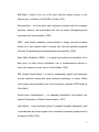
9: BT Chat Acknowledgement
10: Point-to-point connection
11: Actual values for BT Chat Acknowledgement
12: Actual values for Point-to-point connection
22
35
36
36
37
38
39
41
42
43
44
44
vi
LIST OF FIGURES
Figure
Figure
Figure
Figure
Figure
Figure
Figure
Figure
Figure
Figure
Figure
Figure
Figure
Figure
1.1: Conceptual Framework
2.1: C.I.E Color Chart
2.2: TPS62260LED Wireless Remote Control design kit
3.1: Project Design Flowchart
3.2: Design Block Diagram
3.3: RGB Led Panel Set-up
3.4: PIC18F4550 Configuration
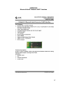
3.5: Bluetooth Serial Converter UART Interface
3.6: Three Terminal Voltage Regulator
3.7: Schematic Diagram
3.9: The PIC18F4550 Microcontroller controlling the Led drivers
3.10: System Flowchart
3.11: The Circuit Board
3.12: The RGB Led Panel
4
12
13
15
20
23
24
25
25
26
28
30
32
33
vii
ABSTRACT
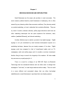
The design is all about the microcontroller-based RGB LED panel. This design
project is very useful as a form of advertisement for small businesses. The
design uses Bluetooth technology as its communication medium for the user
input device to the RGB Led panel. The main purpose of the design project is to
aid small businesses on their struggle against high cost advertisement
techniques. It uses microcontrollers and Led drivers to manipulate the colors
produced by the RGB Led panel. The design is powered by a 12 volts power
supply and is controlled by the PIC microcontroller. The design uses a Bluetooth
module to receive data coming from mobile phones, laptops and desktop
computers. The design can be interfaced with desktop personal computers via a
hyper-terminal that uses RJ11 phone jack.
Keywords: RGB LED, microcontroller, Bluetooth, wireless
viii
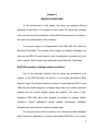
Chapter 1
DESIGN BACKGROUND AND INTRODUCTION
Small Businesses are the major job providers in most economies. The
most common problem faced by small businesses is bankruptcy, this is often
caused by poor planning rather than economic conditions; Poor planning mainly
on product marketing, on how to advertise their products effectively. They can
try word of mouth, customer referrals, yellow pages directories and there are
other marketing techniques but are quite expensive like television, radio,
outdoor (roadside billboards), and internet marketing.
Another effective way to market a product is by digital signage. Digital
signage is not yet considered by most business development experts as a
marketing technique, because they are simply unaware of its value.
Digital
signage costs less compared to that of broad-based media such as TV,
newspapers, radio and yellow pages, and it is usually a one-time investment.
Another thing to keep in mind is the longevity of the medium. All other media
stop as soon as you quit paying for it.
There is a need for a design of an RGB LED Panel via Bluetooth
Technology that has commercial features and can allow users to change their
messages in “real time”, to reach target audience without delay. This can result
to a more efficient and economical design that can allow low-budget
establishments or small businesses to purchase their own display systems.
1
Statement of the Problem
Marketing techniques help small businesses promote their products or
services to the general public.
More exposure to the public means better
revenue. This allows small businesses to increase their revenue, thus, having an
opportunity to expand their market.
Small businesses spend a lot of money for the endorsement of their
products.
Problems may arise using various marketing techniques such as,
signboards, tarpaulin, flyers, posters, etc. These marketing techniques are often
costly because of printing multiple posters, flyers, and tarpaulins, and will
eventually be trashed once the endorsement theme or event is done. Moreover,
the disposal of these materials may cause environmental hazards, due to most
of the materials are non-biodegradable.
Objective of the Design
The general objective of the design is to produce a LED panel that can
display user input messages in seven different colors using Bluetooth
technology. The design aims to:
1. Develop a low-cost Digital Signage that can be made using available
parts and materials locally.
2. Develop a compact Digital Signage design which aims to target a
specific audience.
3. Generate seven different colors that can be used as font colors for the
messages that will be displayed in the RGB LED Panel.
2
4. Use Pulse Width Modulation or PWM on four RGB LEDs so that it can
display multiple colors that the RGB LED can produce.
5. Improvise a software that can act as a bridge between the mobile
phone and the RGB LED Panel.
Significance of the Study
The design has a global impact for the business owners. With the
implementation of this project, marketers and business owners will have access
to a cost-effective medium for advertising their products and services. It is not
only simple and easy to use but the product itself is also affordable even to the
small and medium Entrepreneurs. It would be a great advertising tool because it
allows users to change their messages in “real time”, to reach target audience
without delay.
The design has an environmental impact. With the use of this design, it
can minimize the use of paper posters, flyer advertisements, tarpaulins and the
like which add to the amount of waste dumped. This can help in lessening the
garbage in the society.
3
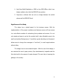
The Conceptual Framework
Input
- Data to be
displayed in the
Panel.
Process
- Convert input
data to ASCII.
- Define color to
be used.
- Color of the
data when
displayed.
Output
- Display the
ASCII
characters in
the RGB Panel
with the
corresponding
color.
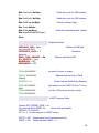
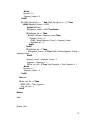
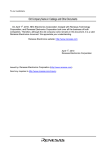
Figure 1.1 – Conceptual Framework
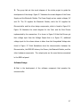
Figure 1.1 shows the RGB LED display system’s structure and
functionalities. It is divided into three stages, the Input, the Process, and the
Output of the system.
Based on Figure 1.1, the user must input certain variables for the
prototype to operate. First, the user must input the data he or she wishes to be
displayed in the RGB Panel. This is done via Bluetooth Technology. The user
must have a software application called “Bluetooth Chat” installed in his mobile
phone for the data transmission to be successful. Lastly, when the message is
already displayed in the RGB LED display panel, the user can change the font
color of the displayed message.
After the users input data, it can now go to its processing where the
Bluetooth Module converts the raw data that are sent via Bluetooth to its
corresponding ASCII characters. Then, the data are sent to the input port of the
microcontroller. The microcontroller processes the data and controls the Column
4
and Row drivers of the design to which RGB LED lights up which color to emit.
After the Processing Stage, the user input message or text can now be seen in
the RGB LED Panel and displays the desired font color.
Scope and Delimitation
Since it is the objective of the study to develop a cost-efficient Digital
Signage, the design consists of readily available components in the market. The
design is compact and easy to use with the proposed operation via Bluetooth
technology.
The study also covers the implementation and assessment of the
prototype as to its usability in different conditions and the acceptance of both
the advertisers and the target audience.
The Digital Signage displays text data that are sent thru Bluetooth. The
text input comprises of letters, numbers and special characters. The letters
displayed are all in upper case as a limitation on the matrix of the design.
The display panel is 8x40 RGB LED matrix. The panel displays up to 240
characters per message. The design uses Bluetooth from mobile phones to send
messages which is advantageous because it doesn’t require money every time
the user sends a note or a message; much cheaper and much efficient
compared to SMS developed designs. The input device must have a software
called “Bluetooth Chat” installed. The “Bluetooth Chat” software acts as a bridge
between the input device and the RGB LED Panel. Sending data to the RGB LED
5
Panel via SMS or infrared messaging will not work. The limited distance between
the mobile phone and the design is up to 10 meters.
With constraints such as timeframe and funding for the development of
the prototype, the project is limited only to a small design that can only display
text messages of varying colors, though it shall consist of components that can
display animated images.
Definition of Terms
LED - A light-emitting diode (LED) is a semiconductor diode that emits light
when an electrical current is applied in the forward direction of the device (Basic
Electronics, 2003).
RGB LED - is a LED (Light Emitting Diode) that emits three primary colors of red,
green and blue (Scherz, 2000).
Battery - is a device that changes chemical energy into electrical energy. It
consists of a number of connected units called cells which convert the energy
into electrical current (Bell, 2007).
Hardware - is the physical components of a computer system (Stalling, 2006).
Bluetooth®
Technology
-
is
a
wireless
protocol
utilizing
short-range
communications technology that facilitates data transmission over short
distances from fixed and mobile devices, creating wireless personal area
networks (Wireless and Cellular Telecommunications, 2006).
6
RGB Panel - Refers to the use of flat panel electronic display devices; in the
designs case, a collection of RGB LEDs (Trundle, 2001).
Microcontroller – Is a chip which has a computer processor with all its support
functions, memory, and input/output built into the device (Programming and
customizing the microcontroller, 1999).
PSOC - most closely resembles a microcontroller in usage, since the programs
written by a user execute code to interact with the user-specified peripheral
functions (Programming and customizing the microcontroller, 1999).
Pulse Width Modulation (PWM) – is a signal that involves the modulation of its
duty cycle, to either convey information over a communications channel or
control the amount of power sent to a load (Roddy, 1995).
PCB (Printed Circuit Board) - is used to mechanically support and electrically
connect electronic components using conductive pathways, or traces, etched
from copper sheets laminated onto a non-conductive substrate (PCB Design by
Chris Stahl).
Point-to-point communication - is a dedicated transmission link between two
devices (Introduction to Mobile Communications, 2007).
Input device – is any peripheral (piece of computer hardware equipment) used
to provide data and control signals to an information processing system such as
a computer (Miller, 2007).
7
Interface – is a device or program enabling a user to communicate with a
computer, or for connecting two items of hardware or software (Stone, Stone
and Jarett, 2005).
Power Supply – pertains to the voltage supply needed by the RGB LED display
system for operation (Gumhalter, 1986).
Wireless – It is operated by means of transmitted electromagnetic waves. No
wires or connectors to be used in sending or receiving data (Wireless and
Cellular Telecommunications, 2006).
8
Chapter 2
RELATED LITERATURE
In the development of this design, the group has explored different
materials to help them in the progress of their study. The group had consulted
online journals as well as publications that tackled and discussed the concepts to
be used in the advancement of the prototype.
The group’s design is a Programmable 24-bit RGB LED Color Panel via
Bluetooth Technology. The concept of the design is to display a message or a
note into an RGB LED panel where it can be modulated to produce any color
that is desired. Data Transferring is achieved through Bluetooth Technology.
RGB LEDs operate in extreme outdoor conditions
One of the important concerns that the group has considered is the
location of the RGB LED panel, on where it is to be used. According to Emily
Gleason, Avago Technologies developed a series of high-brightness SMT tri-color
LEDs that will enable designers to develop large indoor and outdoor electronic
displays that will provide sharper images and graphics. The series of highbrightness RGB LEDs have been designed to operate in extreme outdoor
conditions. Typical
applications
include
stadium
scoreboards, billboards,
marquee signs and electronic variable messages signs.
The group’s design which is similar to the ‘electronic variable messages
signs’ knows the importance of choosing the suitable RGB LED for the project.
9
The group has considered the one that displays most visibility and can be seen
at stiff viewing angles; the RGB Quad-LED offers a viewing angle of 120° for
large display.
In this article, it stated that the RGB LED light output can be affected by
the PCB temperature where the LEDs are soldered and the elevation
temperatures will also result in further degradation of the light output. At 55
degrees Celsius, it would approximately cost the light output 15% - 20% lower.
It is helpful for the group’s design, so that if the design is to be installed, it
would be placed in a shaded area, away from the sun.
Wireless Smart Remote Display System (WSRD)
An innovation that is comparable to the group’s study is the Wireless
Smart Remote Display System developed by Scanning Devices Inc. last 2002.
This device was designed to provide fast digital readings in industrial and
process control situations where a remote display is required for operator
convenience.
According to the developer of WSRD, the system consists of:
•
One base station - a Bluetooth enabled display linked to the data source
by either RS232 or 20 milliamp current loop connection. The base station
learns transmission characteristics, receives data from the source,
constructs messages, manages the Bluetooth Network and transmits
messages wirelessly to the remote displays.
10
•
Up to 7 remote displays - any Scanning Devices Smart Remote Display
linked to the base station by Bluetooth wireless communications.
This system uses Bluetooth radio module power class 2 with specified
range of only 10 meters and a selection of bright yellow reflective
electromechanical and bright red LED displays that provides readability. The
group’s innovation to this design is the implementation of RGB LEDs in the
display which can be modulated to control the brightness and to provide
excellent readability anytime and anywhere. The 10 meter range can also be
extended using another version of bluetooth module that can transmit up to 100
meters.
Pulse Width Modulation
According to A.K. Gelig of IEEE, Pulse-width modulation (PWM) of a signal
or power source involves the modulation of its duty cycle, to either convey
information over a communications channel or control the amount of power sent
to a load. In relation to the group’s design, changing the duty cycle of each
PWM signal can control the average current flowing through each RGB led
creating any color desired. In this project, the duty cycle is the ratio of ON or
OFF time to the total time the LED was ON and OFF.
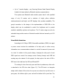
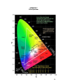
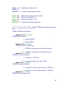
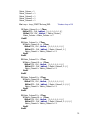
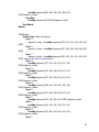
The mixing of colors from red, green and blue to produce any other color
is described in the CIE color chart (figure 2.1). The CIE chart is a triangular
wedge which shows all the colors the eye can see where the top left corner is
pure green, the bottom right is pure red and the bottom left is pure blue. The
11
numbers on the perimeter are corresponding wavelength (in nanometers) .The
inscribed triangle is a demonstration of actual color generated. For example,
let’s say our RGB LED can generate the following pure wavelengths: 700nm
(red), 545nm (green) and 400nm (blue). These would correspond to the points
plotted on the CIE chart and so we can make any of the colors inside the
triangle, but none outside of it.
Figure 2.1 – CIE Color Chart
To change the duty cycle of the PMW signal to each of the LED, a
different period of delay should be set for the time it is ON and OFF. Consider a
LED set to ON state for 1ms and then set to OFF state for 3ms, since the LED is
OFF 3 times longer that it was ON the positive duty cycle is 25% of the time
(1ms / 4ms) and the negative duty cycle is 75% of the time ( 3ms / 4ms). This
makes the RGB LED produces other colors.
12
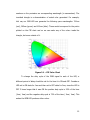
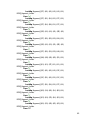
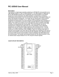
TPS62260LED Wireless Remote Control RGB LED design kit
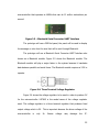
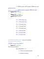
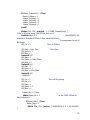
Figure 2.2 - TPS62260LED Wireless Remote Control RGB LED design kit
This design related to the group’s study is a new product of Texas
Instruments Incorporated. According to the author, the TPS62260LED Board
controls the color and brightness of RGB LEDs or runs an automatic color light
animation program. It can utilize wireless communication by using eZ430RF2500 (RF development tool) which is plugged directly to the board. This
allows designers to create a lighting network of RF controlled lamps.
Using wireless technology same as ours, flexibility is obtained as well as
additional infrastructures are eliminated. Using Bluetooth will be more
convenient than RF as quoted by Bortman (2002), Bluetooth is a protocol that
allows short-range communication among computers, cell phones, printers,
keyboards, mice and other electronic device. There are a lot of Bluetoothenabled devices available that can be used to transmit signals.
13
CHAPTER 3
DESIGN METHODOLOGY AND PROCEDURES
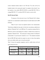
Design Methodology
Constructive research was used as the design methodology. Constructive
research is perhaps the most common computer science research method. This
type of approach demands a form of validation that doesn’t need to be quite as
empirically based as in other types of research. The study was composed of
Gathering of the Data and Materials, Prototyping, Prototype Testing and
Validation. The design was patterned mainly on the existing LED matrices
available in the market. This design is a stand-alone microcontroller-based
prototype. The design procedure part provides further explanation of the
method, and a step by step procedure is discussed.
Design Procedure
The design as stated above follows the Constructive research method.
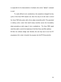
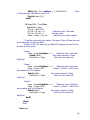
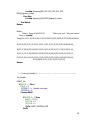
Figure 3.1 located on the next page further explains the step by step method.
The design was separated in three parts: the first part being the data gathering
and prototype designing, second is the hardware part and the last part is the
software design. The data gathering and designing involve the library research
and interviews the researchers have done. The researchers established a block
diagram to guide the whole process of designing. The block diagram serves as
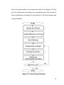
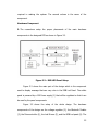
a backbone of the design, as seen on Fig. 3.2. Fig. 3.2 shows the components to
be used. The hardware part basically involves building the circuit and this part
14
shows the interconnection of the components based on the design in the first
part. The software part of the design is the programming part. This involves the
proton programming to program the microcontroller. (See each respective part
for specific details).
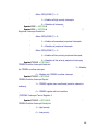
Figure 3.1: Project Design Flowchart
15
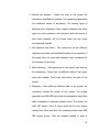
1. Identify the problem – Before the start of the project the
researchers identified the problem. The researchers determined
the ineffective means of advertising. The existing types of
advertising like tarpaulins, flyers roadside billboards and other
types are more expensive, and moreover after the period of
time these materials will be thrown away and can cause
environmental hazards.
2. Set objectives and tasks – The researchers set the different
objectives and tasks and distributed equally to the members of
the group. Also, the scope and limitations were considered for
the outcome of the project.
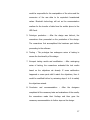
3. Data Gathering – Data gathering for the project was done by
the researchers. Topics from the different fields of the project
have been studied. These were used during the start of the
project.
4. Designing – After gathering sufficient data for the project, the
researchers started the design of the project. The project
generally used RGB LED that would be manipulated using Pulse
width modulation to generate multiple colors. The design has
eight LED drivers, three of which would be the color drivers
namely Red, Green and Blue. The remaining drivers were RGB
LED column drivers. Then the program needed in which it
16
would be responsible for the manipulation of the colors and the
conversion of the raw data to its equivalent hexadecimal
values. Bluetooth technology will act as the communication
medium for the transfer of data from the mobile phone to the
LED Panel.
5. Prototype production – After the design was laid-out, the
researchers then proceeded on the production of the design.
The researchers first accomplished the hardware part before
proceeding to the software.
6. Testing – The prototype has undergone series of testing to
ensure the functionality of the design.
7. Interpret testing results and modification – After undergoing
series of testing, the researchers evaluated the test results
based on the objectives set already. If some malfunction
happened or some parts didn’t match the objectives, then it
would be modified further by reviewing steps 4 to 6 to satisfy
the objectives missed.
8. Conclusion
and
recommendation
–
After
the
designers
completed all the necessary tests and evaluations of the results,
the researchers made their findings and then gave the
necessary recommendation to further improve the design.
17
I. Data Collection
1. The first step the researchers had taken was to find the perfect RGB LED for
the RGB LED display panel that the design was going to use. The researchers
conducted a study about the different kinds of RGB LED.
After studying and comparing the RGB LEDs, the researchers were able to
identify which RGB LED was best suited for the design.
The researchers
preferred to use RGB Quad-LED over Tri-LED because the former was easier to
manipulate. A typical RGB Tri-LED has its Red pin as Anode, the Blue and Green
pins as Cathode. While in RGB Quad-LED, the fourth pin could be an Anode or
Cathode wherein the color could be easily manipulated through the concept of
PWM.
2. Because
the
design
implements
communication
via
Bluetooth,
the
researchers studied about the latest on Bluetooth technology. The device is
called Bluetooth module, a transceiver, will be used in receiving raw data from
the input device.
3. The group had identified a way to make sure that the Bluetooth connection
was secured because almost every mobile phone and laptop had an available
Bluetooth device. This part of the study is the most crucial part of the design.
After hours and hours of trial and error, the researchers decided to go with a
special program called “Bluetooth Chat” that was installed in the input device.
Also, point-to-point communication was implemented in the designs Bluetooth
18
communication so that only one user could access the RGB LED display panel at
a time.
4. The researchers focused on how to display characters in the RGB led panel.
This was done using the microcontroller that decoded the incoming data and
converted it to its hexadecimal value, then it was passed to the RGB led drivers.
The RGB led drivers controlled the RGB leds on which should lit on and what
color. The RGB led panel matrix was 8x40 where in each character segment was
8x8.
5. Furthermore, the researchers determined the effective principles that could
be used in order to control the desired output. The most suited idea that could
give the desired variable output was Pulse Width Modulation (PWM). This
principle was responsible for altering the duty cycle which depended on the
input current coming from the drivers. During the process of designing the
project, the researchers studied and applied methods and principles of Pulse
Width Modulation. Pulse Width Modulation was used in the development of the
design. PWM was responsible for the control of the current directed to the RGB
led, thus changing the colors that it displayed.
19
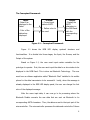
II. Prototype Designing
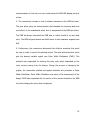
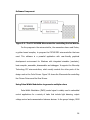
Figure 3.2: Design Block Diagram
The researchers established a block diagram to guide the whole process
of designing. The block diagram served as a backbone of the design. Fig. 3.2
illustrates the block diagram used by the group. These could be broken down to
5 phases.
1. The design used RGB Quad-LED because it could be easily manipulated
through the concept of Pulse Width Modulation.
20
2. The design used RGB LED drivers. The 8 led drivers were categorized into
two. The first type was three color drivers for Red, Blue and Green. The second
type was five led drivers for the RGB LED panel columns.
3. Construct a program that would be embedded in the microcontroller, so that
it would be responsible for all the processes in the design which included
manipulation of colors in the panel and the conversion of raw data to its
equivalent hexadecimal values.
4. The design used a component called Bluetooth module, a transceiver that
would be used in receiving raw data from the input device.
5. The design project used 12 volts of power supply in order to operate the
whole design. The 12 volts supplied the voltage needed by the microcontroller,
the LED drivers, the circuit and the Bluetooth Module. Since, the microcontroller
and the RGB leds needed 5v supply while the Bluetooth module needed 3.3v
supply, two voltage regulators were used.
6. After completing the 5 phases, the last step was to make a PCB layout for the
connection between the microcontroller, the LED drivers and the Bluetooth
module and other components in order for the design to work. After finalizing
the layout, the PCB and all the components were fabricated and installed.
21
Design Procedure for Actual Design
The researchers discussed both software and hardware specifications
separately in this section. The job done by the software part is discussed later in
this section.
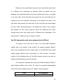
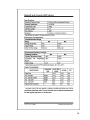
1. First, the group gathered all the materials needed in the development of the
design as listed in Table 1 – List of Materials.
Quantity
360
1
3
1
2
1
1
1
1
1
8
3
3
3
1
1
1
1
1
1
5
1
Description
RGB quad-LED
100 uF Capacitor
0.1 uF Capacitor
1000uF Capacitor
20 pF Capacitor
1N4001 Diode
Phone jack
CON6AP connectors
CON5 connectors
Connector Rectangle 17x2
Connector Rectangle 8-pin
MAX6971 LED Drivers
100 ohm Resistor
10 ohm Resistor
470 ohm Resistor
SPDT switch
PIC18F4550 Microcontroller
LT1086 3.3 Voltage Regulator
LT78L05A Voltage Regulator
CD4049UB Buffer
74VHC595 Column Drivers
Crystal pin
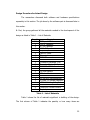
Table 1 - List of Materials
Table 1 shows the list of materials significant in building of the design.
The first column of Table 1 indicates the quantity or how many items are
22
required in making the system. The second column is the name of the
component.
Hardware Component
2. The researchers setup the proper placements of the main hardware
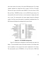
components in the designed PCB as shown in Figure 3.3.
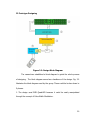
Figure 3.3 – RGB LED Panel Setup
Figure 3.3 shows the main part of the design which is the component
used to display message that can vary color in the RGB Led Panel. The whole
panel is powered by a 12V Power supply (1) that will be regulated so that it can
be used by the panel components.
Figure 3.3 shows the setup of the whole design. The hardware
components of the design are the voltage regulator (2), the Bluetooth Module
(3), the Microcontroller (4), the Led Drivers (5), and the RGB Led panel (6). The
23
main board contains the circuitry of the whole RGB display panel. The voltage
regulator regulates the voltage that will be coming in from the 12V supply.
There are two types of led drivers used. MAX6971 is the color drivers for Red,
Blue and Green. 74VHC595 led driver is for the RGB LED panel columns. The
microcontroller will control the drivers on what characters to display and which
color to emit. The microcontroller will receive signals through the Bluetooth
module. It will then convert the signals to its equivalent hexadecimal value. The
RGB Led panel will display the message that the user will input.
Figure 3.4 – PIC18F4550 Configuration
Figure 3.4 shows the pin configuration of microcontroller chip used in the
design. The microcontroller serves as the main processor of the design which
has the capability to store program that must be implemented in the design.
The microcontroller used is PIC18F4550, a 40 pin 16-bit with a CMOS flash
24
microcontroller that operates at 48MHz that can do 12 million instructions per
second.
Figure 3.5 – Bluetooth Serial Converter UART Interface
The prototype will use a RGB led panel, the panel will be used to display
the message or note from the user that will be sent through Bluetooth.
The prototype will use a Bluetooth Serial Converter UART Interface also
known as a Bluetooth module. Figure 3.5 shows the Bluetooth module. The
Bluetooth module will play a major factor in the system because it translates
data between parallel and serial forms. The Bluetooth module requires a 3.3V to
operate.
Figure 3.6: Three Terminal Voltage Regulator
Figure 3.6 shows the voltage regulator to be used in order to produce 5V
for the microcontroller. LM7805 is the model name of the voltage regulator
used. This voltage regulator is a three terminal regulator that produces fixed
output voltage which is 5V. This is important because the driver voltage of the
microcontroller
is
only
5v.
Excess
voltage
may
damage
the
IC.
25
Circuit Design
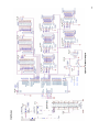
Figure 3.7 – Schematic Diagram
26
3. The group laid out the circuit diagram of the whole project to guide the
development of the design. Figure 3.7 illustrates the circuit diagram of the Power
Supply and the Bluetooth Module. The Power Supply as two output voltages, 3V
and 5V. The 3V supplies the Bluetooth Module; while the 5V supplies the
Microcontroller and the other design components, which is found in Figure 3.8.
Figure 3.8 illustrates the circuit diagram for the Color and the Row Drivers
implemented by the researchers. It is shown in Figure 3.8 that the Drivers get
their voltage input from the Voltage Output that is in Figure 3.7, additional
voltage input for the column drivers is taken from the Unregulated Voltage also
found in Figure 3.7. Both illustrations show the interconnection between the
Microcontroller, the RGB LED drivers, the Drivers, the Bluetooth Module, and the
other hardware components. The output ports are the ones that are connected
to the RGB Led panel.
Software Design
4. Next is the development of the software component that operates the
microcontroller.
27
Software Component
Figure 3.9 –The PIC18F4550 Microcontroller controlling the Led drivers
For the program in the microcontroller, the researchers have used Proton,
a python based compiler, to program the PIC18F4550 microcontroller that was
used. This software is a powerful application with user-friendly graphical
development environment for Windows with integrated simulator (emulator),
basic compiler, assembler, disassembler and debugger. It supports the Microchip
Technology PIC microcontrollers, which mostly controls the other parts of the
design such as the Color Drivers. Figure 3.9 shows the Microcontroller controlling
the Column Drivers and the Row Drivers.
Using Pulse Width Modulation to generate multiple colors
Pulse-Width Modulation (PWM) control signal is widely used in embedded
control applications for a variety of tasks that include light dimming, output
voltage control and communication between devices. In the groups’ design, PWM
28
is responsible for the demonstration of multiple colors when “@demo” command
is used.
To create different color combinations, the researchers changed the duty
cycles of the three PWM outputs over time. One way to do this was to control
the three PWM duty cycles with a three phase sinusoidal profile. This generated
a rotating (color) vector that would sweep smoothly across the chromaticity
plane generating a wide range of color combinations. The three PWM signal
would be used to control the brightness of the Red, Green and Blue emitters.
5. After the software design was finished, the next step was to use the PIC
programmer kit in order to transfer the program into the PIC Microcontroller.
29
System Flowchart
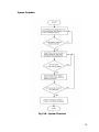
Fig 3.10 – System Flowchart
30
Figure 3.10 is the system flowchart of the prototype. It briefly shows how
the operation of the design starts and when does it end. As shown in the figure,
the process starts as the system is turned ON. It will first display the default
message that is stored in the Flash storage that is in the microcontroller. Then it
will then check on whether the Bluetooth Module is sending a message.
If the Bluetooth Module is sending a message, each character in the
message will be then checked, if each character is in the microcontroller’s lookup
table. If a character is not in the microcontroller’s lookup table, it will skip this
character and move on to the next one. Meanwhile if the character is in the
microcontroller’s lookup table, this character will be sent to the ‘Data’ Array
which will be used in displaying the characters.
It will now check if the character is the end of the message character, if
not it will go back and get the next character that is sent. Meanwhile, if it is the
end character, then it will not display all contents of the ‘Data’ Array in the RGB
Led Panel.
31
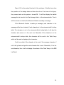
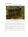
Prototype Development
6. Last is the development of the circuit board and the RGB LED panel.
Fig 3.11 – The Circuit Board
The circuit board consists of several components such as the PIC
microcontroller which is the overall controller of the RGB LED panel. It also has
two types of drivers. The first type is the column drivers; these drivers
manipulate the column segment of the panel. The second type is the row and
color drivers; these manipulate the color of the panel and the row part of the
panel. The circuit board has five ports of an eight-pin connected to the panel.
Lastly, it has a voltage regulator that supplies the power for the whole design
project.
32
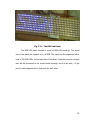
Fig 3.12 – The RGB Led Panel
The RGB LED panel consists of series of RGB LEDs lined up. The actual
size of the panel per segment is 8 x 8 RGB. The panel has five segments with a
total of 320 RGB LEDs. At the back side of the panel, it has the provision of wires
that will be connected to the circuit board thorough via an 8-pin port; 1 8-pin
port for each segment also 1 8-pin port for each color.
33
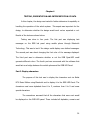
Chapter 4
TESTING, PRESENTATION AND INTERPRETATION OF DATA
In this chapter, the design was tested to further determine its capability in
handling the operation of the whole system. This aspect was important for the
design, to determine whether the design would work out as expected or not.
Results of the tests are shown below.
Testing was done in four parts. The first part was displaying text
messages on the RGB led panel using mobile phone through Bluetooth
Technology. This was to test if the design could display user defined messages.
The second part was about changing the font color of the message displayed.
The third part was to determine whether or not the RGB Quad-LED could
generate different colors. The fourth part was concerned with the software that
would act as a bridge between the mobile phone and the RGB LED Panel.
Part I: Display characters
The purpose of this test was to display the characters sent via Nokia
N70 Music Edition using Bluetooth and to display it to the RGB LED Panel. The
characters used were alphabets from A to Z, numbers from 0 to 9 and some
special characters.
The researchers assumed that all the characters that were sent would
be displayed on the RGB LED panel. These included all alphabets, numeric and
34
some special characters. All sent characters would be displayed with respect to
their types and cases.
The procedure conducted by the researchers for this part is as follows:
1. Connect the mobile phone (N70 Music Edition) to the RGB LED Panel via
Bluetooth Technology. The mobile phone must have an application called
“Bluetooth Chat”, which acts as a communication medium for both parties.
After a successful connection;
2. The researchers typed the default syntax, “@msg” then followed by the
desired characters for testing. After typing the desired characters;
3. The researchers send the message to the RGB LED Panel. The table below
shows the results of the test.
Input Character
Output Character
A,a
B,b
C,c
D,d
E,e
F,f
G,g
H,h
I,i
J,j
K,k
L,l
M,m
N,n
O,o
P,p
Q,q
R,r
S,s
T,t
A,A
B,B
C,C
D,D
E,E
F,F
G,G
H,H
I,I
J,J
K,K
L,L
M,M
N,N
O,O
P,P
Q,Q
R,R
S,S
T,T
35
U,u
V,v
W,w
X,x
Y,y
Z,z
U,U
V,V
W,W
X,X
Y, Y
Z,Z
Table 2 - Character Display (Alphabet)
Input
0
1
2
3
4
5
6
7
8
9
Output
0
1
2
3
4
5
6
7
8
9
Table 3 - Character Display (Numerical)
Input Character
!
@
<
>
?
.
,
:
Output Character
!
@
<
>
?
.
,
:
Table 4 - Character Display (Special Characters)
The researchers sent characters A to Z to the RGB LED Panel and the
same characters were displayed on the RGB LED panel. When the researchers
sent lower case characters a to z to the RGB LED Panel, the output characters
remained in their respective upper case equivalent.
The Panel encountered
problems displaying lower case characters that exceeds the 5x7 character frame,
characters such as “g”, “q”, “j”, “y” and “p”; that is why the RGB LED Panel is
36
programmed to display all Alphabet characters to be in their respective upper
case equivalent. The test results for sending numerical characters 0 to 9 to the
RGB Panel are shown in Table 6. The test results for sending special characters
are shown in Table 7.
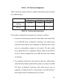
Part II: Testing the seven colors that can be displayed in the RGB
Panel.
The testing is about changing the font color of the messages displayed
on the RGB LED panel. It is important to have different font colors for an RGB
LED Panel that is designed for product marketing. This allows users to have the
flexibility on promoting their products, by trying on different colors to attract
audiences.
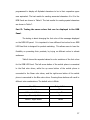
Table 8 shows the expected values for color variations of the font colors
for the RGB LED Panel. The left arrow button of the mobile phone is connected
to the Red color driver; while the up arrow button of the mobile phone is
connected to the Green color driver, and the right arrow button of the mobile
phone is connected to the Blue color driver. Pressing these buttons will result to
different color combinations. The default color is White.
Condition
Output Color
Default
White
White + Left Button
Aqua Blue
Aqua Blue + Up Button
Blue
White + Right Button
Yellow
Yellow + Left Button
Green
37
Default + Up Button
Violet
Violet + Right Button
Red
Table 5 – Expected values for color variation
The procedure conducted by the researchers for this part is as follows:
1. First connect the mobile phone (N70 Music Edition) to the RGB LED Panel
via Bluetooth Technology with Bluetooth Chat application to be able to
communicate to the RGB LED Panel. After a successful connection,
2. Type a test message, “@msg FONT COLOR TEST”. After typing the
desired characters,
3. Send the message to the RGB LED Panel. When the message is already
displayed,
4. Use the keypad arrows (left, right and up) on the mobile phone to create
different color combinations.
The table below shows the results of the test.
Condition
Output Color
Default
White
White + Left Button
Aqua Blue
Aqua Blue + Up Button
Blue
White + Right Button
Yellow + Left Button
Default + Up Button
Yellow
Green
Violet
Violet + Right Button
Red
Table 6 – Actual values for color variation
38
Referring to the results taken during the test, each button would result
to a different color combination as expected. When the default color was
displayed, this would mean that the red, green and blue colors were on, resulting
to the color white. As the left button was pressed, the color red would shut off,
resulting to the color Aqua Blue. Going back to the default color white, if the
right button was pressed, this would shut off the color Blue and would display
the color Yellow. Going back again to the default color white, if the up button
was pressed, the color green would be turned off, displaying color Violet.
Pressing these arrow keys would result to different color combinations. This
would result to 7 different colors as shown in Table 9.
Part III: Generate the multi-colors produced by the RGB Led
The purpose of this test was to verify if the Pulse Width Modulation
actually work to the design. It also tested if the special command “@demo”
which when transmitted from the mobile phone to the RGB LED Panel would
actually display different colors continuously for 26.22 seconds. The distinct
number of colors displayed was not 16 million because a person’s eye was not
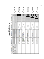
capable of distinguishing every color transition.
The researchers assumed that using Pulse Width Modulation (PWM) it
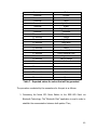
would display multiple colors. Table 10, shows the expected distinguishable
colors that would be displayed when the “@demo” was transmitted:
Time
1 second
Color Displayed
White
39
2 seconds
3 seconds
4 seconds
5 seconds
6 seconds
7 seconds
8 seconds
9 seconds
10 seconds
11 seconds
12 seconds
13 seconds
14 seconds
15 seconds
16 seconds
17 seconds
18 seconds
19 seconds
20 seconds
21 seconds
22 seconds
23 seconds
24 seconds
25 seconds
26 seconds
Pink
Orange
Yellow
Neon
Light Green
Green
Bright Turquoise
Turquoise
Turquoise
Purple
Light Blue
Aqua Blue
Blue
Azure
Amaranth Pink
Cherry Blossom Pink
Bright Pink
Carrot Orange
Amber
Chartreuse Yellow
Lime
Green-Yellow
Jade
Aqua
Cyan
Table 7 – Expected values for colors that will be generated
The procedure conducted by the researchers for this part is as follows:
1. Connecting the Nokia N70 Music Edition to the RGB LED Panel via
Bluetooth Technology. The “Bluetooth Chat” application is used in order to
establish the communication between both parties. Then,
40
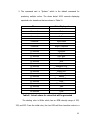
2. The command sent is “@demo” which is the default command for
producing multiple colors. The demo lasted 26.22 seconds displaying
expected color transitions that are shown in Table 11.
Time
1 second
2 seconds
3 seconds
4 seconds
5 seconds
6 seconds
7 seconds
8 seconds
9 seconds
10 seconds
11 seconds
12 seconds
13 seconds
14 seconds
15 seconds
16 seconds
17 seconds
18 seconds
19 seconds
20 seconds
21 seconds
22 seconds
23 seconds
24 seconds
25 seconds
26 seconds
Color Displayed
White
Pink
Orange
Yellow
Neon
Light Green
Green
Bright Turquoise
Turquoise
Turquoise
Purple
Light Blue
Aqua Blue
Blue
Azure
Amaranth Pink
Cherry Blossom Pink
Bright Pink
Carrot Orange
Amber
Chartreuse Yellow
Lime
Green-Yellow
Jade
Aqua
Cyan
Table 8 – Actual values for colors that will be generated
The starting color is White which has an RGB intensity range of 255,
255, and 255. From the initial color, the four LEDs will then transition colors in a
41
counter clockwise direction based on the CIE chart. The colors will be the
transition based on the varying clock pulse. For example at time interval 1 sec,
the transition is from (white) RGB 255-255-255, to (pink) RGB 255-17-255, to
(orange) RGB 255-17-17, to (yellow) 255-255-0, and so on and so forth.
Part IV: Security Tests
The purpose of this test was to know if the “Bluetooth Chat” software
could work as a communication medium between the mobile device and the RGB
LED Panel.
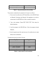
Tables 10 and 11 show the expected results for the Communication
Tests that are divided into two parts; the first test is connecting a mobile phone
without a “Bluetooth Chat” to the RGB Panel. The researchers assumed that the
RGB Panel would not acknowledge the invitation of Mobile Phones without the
application “Bluetooth Chat”. The second part is testing whether the Bluetooth
communication is a point-to-point connection or not. The researchers assumed
that the RGB LED Panel would only accept one user at a time; thus rejecting
other user invitation while a user is currently connected.
Table 10 shows the expected comparative result for mobile phones with and
without “Bluetooth Chat”:
Transmitter
Mobile Phone
without BT Chat
Trial 1
NOT
Acknowledged
Result
Trial 2
Trial 3
NOT
NOT
Acknowledged Acknowledged
Mobile Phone with
BT Chat
User
Acknowledged
User
User
Acknowledged Acknowledged
42
Table 9 – BT Chat Acknowledgement
Table 11 shows the expected results for multiple mobile phones trying to connect
to the RGB LED Panel:
Transmitter
Mobile Phone A with
BT Chat
Mobile Phone B with
BT Chat
Trial 1
Connected
Not Connected
Result
Trial 2
Connected
Trial 3
Connected
Not Connected Not Connected
Table 10 – Point-to-point connection
The procedure conducted by the researchers for this part is as follows:
1. Connect two mobile phones (Nokia N70 Music Edition and a Nokia N90)
to the RGB LED Panel via Bluetooth Technology. One mobile phone
(Nokia N70 Music Edition) has an application of “Bluetooth Chat”, which
acts as a communication medium for both parties. The other mobile
phone (Nokia N90) has no application installed. Mobile A and Mobile B
will try to connect simultaneously to the RGB LED Panel. After finishing
the first part,
2. The researchers followed the second test by which two mobile phones
(Nokia N70 Music Edition and Nokia N73) would try to connect to the RGB
LED Panel via Bluetooth Technology. Both mobile phones have an
application of “Bluetooth Chat” to communicate to the RGB LED Panel.
Both mobile phones will simultaneously try to connect.
43
The table below shows the results of both actual tests:
Transmitter
Nokia N90 without
BT Chat
Trial 1
NOT
Acknowledged
Result
Trial 2
Trial 3
NOT
NOT
Acknowledged Acknowledged
Nokia N70 with BT
Chat
User
Acknowledged
User
User
Acknowledged Acknowledged
Table 11 – Actual values for BT Chat Acknowledgement
Transmitter
N70 with BT Chat
Trial 1
Connected
N73 with BT Chat
Not Connected
Result
Trial 2
Connected
Trial 3
Connected
Not Connected Not Connected
Table 12 – Actual values for Point-to-point connection
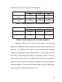
Referring to Table 12, the results are clearly seen in the three trials
made, that the RGB LED Panel only accepts the mobile with the “Bluetooth Chat”
application. The “Bluetooth Chat” application acts as a communication medium
between the mobile phone and the RGB LED Panel. In the second part of the
test, Table 13 shows what kind of Bluetooth connection is used in the design;
based on the results of the test, the design uses point-to-point communication.
Meaning, if a mobile phone is connected to the design, the design will reject all
incoming invitations. The design will be available again, when the mobile phone
that is currently connected decides to disconnect.
44
Chapter 5
CONCLUSION AND RECOMMENDATION
Conclusion
The group was able to develop a design called Programmable 24-Bit RGB
LED Panel via Bluetooth® Technology, using RGB Quad Led to display text
messages in different colors. The design cannot display the 16 million colors
distinctively due to eye limitation which is not capable of seeing each color
transition. The security of the design is very important to keep the integrity of
the data being displayed; this was accomplished by improvising application
software on mobile phones to limit the use of the design.
With the use of the system, small businesses or stores can have an
alternative way to lessen the cost of their advertisement for their products, due
to sending data via Bluetooth® Technology does not require the user to have
load on their mobile phones unlike previous designs that used SMS Technology.
45
Recommendation
More improvements can be made to further enhance the systems
functionality and capability.
Security feature such as authorization of mobile
device before changing the displayed message is one of the enhancements that
the group recommends, so that no one can easily change the displayed message
in the display panel.
Also, for the Bluetooth® range to be extended.
The
display panels can be enlarged as those seen on main highways in the
metropolis. Additional features like display large images and animated images
can further improve this design.
46
REFERENCES
Thomas E. Kissell, Industrial Electronics, Copyright: 2000
Webster Comprehensive dictionary, Encyclopedic Edition, Ferguson publishing
Company, Chicago, Copyright: 2006
Issa Batarseh, Power Electronic Circuits, Copyright: 2004
Myke Predko, Programming and Customizing the Microcontroller, Mcgraw-hill,
Copyright: 1999
William C. Y. Lee, Wireless and Celluar Telecommunications, Mcgraw-hill,
Copyright: 2006
Grob-Schultz, Basic Electronics, Mcgraw-hill, Copyright: 2003
Tony Wakefield, Introduction to Mobile Communications, Auerbach Publications,
Copyright: 2007
Trundle, E. (2001). Newnes Guide to television and video technology, 3rd Edition,
Newnes
Miller, M. ( 2007). Absolute Beginner’s Guide to Computer Basics, 4th Edition,
Que Publishing
Gumhalter, H. (1986). Power supply systems in communications engineering, 2nd
Edition, Siemens Aktiengesellschaft
47
APPENDICES
48
APPENDIX A
Programmable 24-bit RGB LED Color Panel
via Bluetooth Technology
User’s Manual
Prepared by:
Albert M. Agonoy
Antonio Rufo R. Cuenco
Lillette C. Daplas
Mark Dale A. Nieveras
Mapua Institute of Technology
May 2009
49
WARNINGS________________________
To avoid electrical shock, refrain from holding any exposed wires of the
device.
•
This device is intended for adults use only. If the child wants to use the
device, parents should supervise him/her.
•
Avoid prolonged use of the product in dark rooms/areas so to avoid eye
strains.
SAFETY PRECAUTIONS_____________
For your safety, always unplug the device while it is not in use.
The device is mainly used for indoors.
The device uses 220 V of electricity.
Only use the authorized plug adaptor for this device.
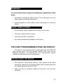
THE 24-BIT PROGRAMMABLE RGB LED DISPLAY
This device is a small-scale model for digital display that uses RGB LED
(light emitting diode). This LED displays multiple colors and uses the
Bluetooth technology. The Bluetooth acts as a communication medium
between the display panel and the mobile phone.
BEFORE USING THE DEVICE_________
•
Only Nokia N70 version mobile phones or early Symbian 60 OS mobile
phones can interact with the device provided that the mobile phone has
an installed application called “BT CHAT”.
•
Make sure that the operating condition of the area is dry and wellventilated.
50
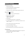
OPERATING THE DEVICE____________
THE RGB LED Panel Display:
1. Open the top flip of the box.
2. Connect the power adaptor to the panel’s power port.
3. Plug the power adaptor to the wall outlet.
4. The panel shows the pre-installed message; the panel is ready for use.
Using the Mobile Bluetooth Chat:
1. Press the
menu button of the N70 mobile phone
2. Select Connectivity → Bluetooth
3. Highlight Bluetooth, then press
Options→ Change→ ON
4. Then press Exit
5. To operate Bluetooth, Select My Own → Bluetooth Chat
6. To connect the mobile phone to the RGB Panel via Bluetooth, select
Options → Connect.
7. When it searches “E-gizmo” Select and press Connect.
8. You are now connected to the Panel.
9. To disconnect, press Option → Disconnect.
10. To Exit, just press the EXIT then it will go back to the My Own Folder.
TO Send Messages
1. Type on the textbox, the “@msg” syntax then followed by 5 spaces then
type the desired message you want to be displayed.
2. Press Options → Send.
51
3. Then it will display the Message you have sent.
TO Show the Color spectrum
1. Type on the textbox “@demo”
2. Press Options → Send.
3. It will show the color spectrum of the Panel.
52
APPENDIX B
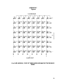
Diagram for Character Loading
t = 1250us
t = 1000us
t = 750us
t = 500us
t = 250us
t = 0us
53
APPENDIX C
Color Spectrum
54
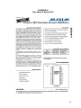
APPENDIX D
Data Sheet of Maxim 6971
55
56
APPENDIX E
Bluetooth Serial Converter UART Interface
57
58
APPENDIX F
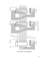
Figures
8 x 8 LED MODULE; FIVE OF THESE MODULES MAKE UP THE RGB LED
PANEL.
59
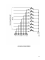
LED MODULE ROW DRIVERS
60
LED MODULE COLUMN DRIVERS
61
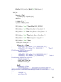
APPENDIX G
Source Code
'****************************************************************
'* Name : UNTITLED.BAS
'* Author : Antonio Rufo R. Cuenco
'* Notice : Copyright (c) 2008 Strategic Instruments
'*
: All Rights Reserved
'* Date : 11/26/2008
'* Version : 1.0
'* Notes : Sourcecode to test DM135 shift-registers
'*
:
'****************************************************************
Device = 18F4550
'Declare XTAL 20
CONFIG_START
PLLDIV = 5
' prescale (Divide by 5 (20 MHz oscillator input)
' default 4mhz result in 48mhz with PLL enabled other osc
input needs to be prescaled
' or divided to have a reult of 4mhz example 20/5 = 4 always
should be 4!!!
CPUDIV = OSC1_PLL2
' postscale [OSC1/OSC2 Src: /1][96 MHz PLL
Src: /2]
USBDIV = 2
' USB clock source comes from the 96 MHz
PLL divided by 2
FOSC = HSPLL_HS
'HS 'HS oscillator, PLL enabled, HS used by USB
FCMEN = OFF
' Fail-Safe Clock Monitor disabled
IESO = OFF
' Oscillator Switchover mode disabled
PWRT = On
' PWRT enabled
BOR = On
' Brown-out Reset enabled in hardware only
(SBOREN is disabled)
BORV = 3
' Minimum setting
VREGEN = OFF
' USB voltage regulator disabled
WDT = OFF
' HW Disabled - SW Controlled
WDTPS = 1024
' 1:1024
MCLRE = On
' MCLR pin Disabled' RE3 input pin enabled
LPT1OSC = On
' Timer1 configured for low-power operation
PBADEN = OFF
' PORTB<4:0> pins are configured as digital
I/O on Reset
CCP2MX = On
' CCP2 input/output is multiplexed with
RC1
STVREN = OFF
' Stack full/underflow will not cause Reset
62
LVP = OFF
ICPRT = OFF
XINST = OFF
' Single-Supply ICSP disabled
' ICPORT disabled
' Instruction set extension and Indexed
Addressing mode disabled
' Background debugger disabled, RB6
and RB7 configured as general purpose I/O pins
CP0 = OFF
' Block 0 (000800-001FFFh) not codeprotected
CP1 = OFF
' Block 1 (002000-003FFFh) not codeprotected
CP2 = OFF
' Block 2 (004000-005FFFh) not codeprotected
CP3 = OFF
' Block 3 (006000-007FFFh) not codeprotected
CPB = OFF
' Boot block (000000-0007FFh) not codeprotected
CPD = OFF
' Data EEPROM not code-protected
WRT0 = OFF
' Block 0 (000800-001FFFh) not writeprotected
WRT1 = OFF
' Block 1 (002000-003FFFh) not writeprotected
WRT2 = OFF
' Block 2 (004000-005FFFh) not writeprotected
WRT3 = OFF
' Block 3 (006000-007FFFh) not writeprotected
WRTB = OFF
' Boot block (000000-0007FFh) not writeprotected
WRTC = OFF
' Configuration registers (300000-3000FFh)
not write-protected
WRTD = OFF
' Data EEPROM not write-protected
EBTR0 = OFF
' Block 0 (000800-001FFFh) not
protected from table reads executed in other blocks
EBTR1 = OFF
' Block 1 (002000-003FFFh) not
protected from table reads executed in other blocks
EBTR2 = OFF
' Block 2 (004000-005FFFh) not
protected from table reads executed in other blocks
EBTR3 = OFF
' Block 3 (006000-007FFFh) not
protected from table reads executed in other blocks
EBTRB = OFF
' Boot block (000000-0007FFh) not
protected from table reads executed in other blocks
Debug = OFF
CONFIG_END
'*************************** Variables Allocations
***************************
Dim CHAR_String[256]
As Byte
63
Dim S_Holder As String * 4
Dim BytesIn[256]
As Byte
Dim A_Holder[4]
As Byte
Dim null
As Byte
Dim CHAR_Column[40]
As Byte
Dim CHAR_count
As Word
Dim Matrix_Column
As Word
Dim Matrix_Column1
As Word
Dim Matrix_Column2
As Word
Dim Matrix_Column3
As Word
Dim Matrix_Column4
As Word
Dim Matrix_Column5
As Word
Dim Segment
As Byte
Dim Segment_holder
As Byte
Dim Speed
As Byte
Dim Segment_Count
As Word
Dim Total_Segment
As Word
Dim Loop
As Word
Dim ind
As Word
Dim Loop_COUNT
As Word
Dim Ram_LEFT
As Byte
Dim CHAR_Reload
As Word
Dim MSSG_END
As Word
Dim dummy
As Word
Dim TIMER0
As TMR0L.Word
Dim Ph_Val
As Byte
Dim StrReload_bit
As Bit
Dim CHANGE_BIT
As Bit
Dim first_run_bit
As Bit
Dim Color_Red
As Bit
Dim Color_Green
As Bit
Dim Color_Blue
As Bit
Dim PWM0
As Bit
Dim PWM1
As Bit
Dim PWM2
As Bit
Dim Loop_bit
As Bit
Dim Demo_bit
As Bit
Dim Demo_flag
As Bit
Dim IntCount As Byte
Dim DutyCycle0 As Byte
' Holds duty cycle for PWM channel
0
64
Dim DutyCycle1 As Byte
' Holds duty cycle for PWM channel
1
Dim DutyCycle2 As Byte
' Holds duty cycle for PWM channel
2
Dim PWMFlags As Byte
Dim Temp As Byte
Dim Phase As Word
Dim BeginPWM As PWMFlags.0
' Used for software flags
' Holds the sinusoidal pointer location
Clear
'*************************** Peripherals Setup
***************************
ONBOARD_USB = False
' Disable the USB and
free the extra RAM
' Maximum
OPTIMISER_LEVEL = 3
optimiser
DEAD_CODE_REMOVE = On
ALL_DIGITAL = True
WARNINGS = OFF
REMINDERS = OFF
TRISA=%00000000
TRISB = %00000001
' Remove redundant ASM
'set ports for input or output
' Make the last four bits of PortB
Outputs
INTCON2.7 = 0
TRISC=%10000000
' Enable Internal PortB Pullup Resistors
'just make sure the USART RX Port C.7 is an
input
TRISD=%00000000
TRISE=%00000000
'and the LCD ports are set up correctly
'**************************** USART Interrupt Setup
***************************
'Declare FSR_CONTEXT_SAVE = off
'On_Interrupt GoTo USART_Int
' define interrupt handler
'INTCON = %11000000
PIE1.5 = 1 ' enable interrupt on USART receive
'RCSTA = $90 ' Enable serial port & continuous receive
'TXSTA = $20 ' Enable transmit, BRGH = 0
65
'SPBRG = 112 ' 4800 Baud @ 48MHz, 0.0%
'SPBRGH = 2
'BAUDCON.3 = 1 ' Enable 16 bit baudrate generator
RCSTA = $90
TXSTA = $24
SPBRG = 225
SPBRGH = 4
BAUDCON.3 =
' Enable serial port & continuous receive
' Enable transmit, BRGH = 1
' 9600 Baud @ 48MHz, 0.0%
1 ' Enable 16 bit baudrate generator
'**************************** T0CON: TIMER0 Control Register Interrupt
Setup ***************************
'
' T0CON: TIMER0 Control Register
'
Symbol TMR0ON = T0CON.7
'
TIMER0 On/Off Control bit
'
1 = Enables TIMER0
'
0 = Stops TIMER0
Symbol T08BIT = T0CON.6
' TIMER0 8-bit/16-bit Control bit
'
1 = TIMER0 is configured as an 8-bit timer/counter
'
0 = TIMER0 is configured as a 16-bit timer/counter
Symbol T0CS = T0CON.5
'
TIMER0 Clock Source Select bit
'
1 = Transition on T0CKI pin
'
0 = Internal instruction cycle clock (CLKO)
Symbol T0SE = T0CON.4
'
TIMER0 Source Edge Select bit
'
1 = Increment on high-to-low transition on T0CKI pin
'
0 = Increment on low-to-high transition on T0CKI pin
Symbol PSA = T0CON.3
'
TIMER0 Prescaler Assignment bit
66
'
1 = TIMER0 prescaler is NOT assigned. TIMER0 clock input
bypasses prescaler.
'
0 = TIMER0 prescaler is assigned. TIMER0 clock input
comes from prescaler output.
Symbol T0PS2 = T0CON.2
'\
Symbol T0PS1 = T0CON.1
' TIMER0 Prescaler Select bits
Symbol T0PS0 = T0CON.0
'/
'
111 = 1:256 prescale value
'
110 = 1:128 prescale value
'
101 = 1:64 prescale value
'
100 = 1:32 prescale value
'
011 = 1:16 prescale value
'
010 = 1:8 prescale value
'
001 = 1:4 prescale value
'
000 = 1:2 prescale value
'**************************** Interrupt Priority Setup
***************************
' INTCON1: Interrupt Control Register 1
'
Symbol GIE = INTCON.7
'
Global Interrupt Enable bit
'
When IPEN (RCON.7) = 0:
'
1 = Enables all unmasked interrupts
'
0 = Disables all interrupts
67
'
When IPEN (RCON.7) = 1:
'
1 = Enables all high priority interrupts
'
0 = Disables all interrupts
'\
Symbol PEIE = INTCON.6
Symbol GIEL = INTCON.6
'/
Peripheral Interrupt Enable bit
'
When IPEN (RCON.7) = 0:
'
1 = Enables all unmasked peripheral interrupts
'
0 = Disables all peripheral interrupts
'
'
When IPEN (RCON.7) = 1:
1 = Enables all low priority peripheral interrupts
'
0 = Disables all low priority peripheral interrupts
Symbol TMR0IE = INTCON.5
'
TIMER0 Overflow Interrupt Enable bit
' 1 = Enables
the TIMER0 overflow interrupt
'
0 = Disables the TIMER0 overflow interrupt
Symbol TMR0IF = INTCON.2
'
TIMER0 Overflow Interrupt Flag bit
'
1 = TIMER0 register has overflowed (must be cleared in
'
0 = TIMER0 register did not overflow
software)
'
' INTCON2: Interrupt Control Register 2
'
Symbol TMR0IP = INTCON2.2
'
TIMER0 Overflow Interrupt Priority bit
'
1 = High priority
'
0 = Low priority
68
''**************************** PIR1: Peripheral Interrupt Request
Register 1 Setup ***************************
' RCON: Reset Control Register
'
'
Symbol IPEN = RCON.7
Interrupt Priority Enable bit
'
1 = Enable priority levels on interrupts
'
0 = Disable priority levels on interrupts
'--------------------------------------------------------------------------INTCON = 0
' Disable Interrupts (just in case)
'
' Setup TIMER0
'
T0PS2 = 0
'\
T0PS1 = 0
T0PS0 =
PSA = 0
' TIMER0 Prescaler to 1:2
'/
0
' Assign the prescaler
T0CS = 0
' Increment on the internal Clk
T0SE = 0
' 0 = Increment On low-to-high
transition On T0CKI pin
T08BIT = 0
' TIMER0 is configured as a 16-bit counter
TIMER0 = 0
' Clear TIMER0
TMR0ON = 0
' Enable TIMER0 off for a while
TMR0IE = 1
' Interrrupt Priorities
TMR0IP = 0
IPEN = 0
69
'******************************* Constants
***************************
IntCount = 32
' Initialise IntCount to 32
DutyCycle0 = 0
'\
DutyCycle1 = 0
' Clear the Duty Cycle Variables
DutyCycle2 = 0
'/
Symbol True = 1
Symbol False = 0
Symbol DTA PORTB.2
Symbol CLK PORTB.3
Symbol Latch_E PORTB.4
Symbol OE_Red PORTB.5
Symbol OE_Green PORTB.6
Symbol OE_Blue PORTB.7
Symbol OE_Col PORTC.2
Symbol EOM = 255'"`"
Symbol Loop_START = 0
Symbol Loop_END = 39
'******************************* Initial Values
***************************
Demo_bit = 0
TIMER0 = 63670
Ph_Val = 255
Phase = 0
first_run_bit = 0
Loop_bit = 1
Speed = 3
Latch_E = 1
OE_Red = 1
OE_Green = 1
OE_Blue = 1
OE_Col = 1
Color_Red = 0
Color_Green = 0
Color_Blue = 0
' Initialise the sinusoidal pointer to 0
HRSOut "Type some characters in the terminal window\n\r",_
"and they will appear on the LCD.",_
"Note that no characters are missed\n\r",_
"even though there is a stupidly large delay within the receiving
loop.\n\r"
' USART Tx Test
70
'----------------------------------------------------------------------------------------------------------------------------------' Include "BUFFERED_HSERIN.INC" ' Load the USART 1 interrupt handler
and buffer read subroutines into memory
'
' INIT_USART_INTERRUPT
' Initiate the USART 1 serial buffer
interrupt
' CLEAR_SERIAL_BUFFER
' Clear the serial buffer and reset its
pointers
'----------------------------------------------------------------------------------------------------------------------------------'
StrN CHAR_String = " <<<<<....MAPUATECH BLUETOOTH MOVING
MESSAGE DISPLAY >>>>>>"
StrN CHAR_String = "
MAPUATECH BLUETOOTH RGB LED MATRIX
DISPLAY!!! ABCDEFGHIJKLMNOPQRSTUVWXYZ 1234567890 < > ! ? @ . , _ "
ON_HARDWARE_INTERRUPT GoTo Int_Handler
'
ON_HARDWARE_INTERRUPT GoTo PWM_InterruptHandler
Declare FSR_CONTEXT_SAVE = Off
GoSub CHANGE_CONTENT
GoSub STORE_ARRAY
INTCON.7 = 1 ' enable interrupts
INTCON.6 = 1
GoTo Start
''''' S T O R E
R A Y ''''''
CHARACTER
COLUMN
SEGMENTS
IN
AR
STORE_ARRAY:
For ind = 0 To CHAR_count
' Fill in Character Arrays
with Segments
' 5 characters at a time
If CHAR_String[ind] >= "A" And CHAR_String[ind] <= "_" Then
71
While Segment_holder <> EOM
GoSub UPPERcase
If Segment_holder = EOM Then Break
If StrReload_bit = 1 Then
If CHAR_Reload = Segment_Count Then
Segment_Count = 0
CHAR_Column[Segment_Count] = Segment_holder
StrReload_bit = 0
EndIf
EndIf
If StrReload_bit = 0 Then
If Segment_Count < 40 Then CHAR_Column[Segment_Count] =
Segment_holder
EndIf
Segment_Count = Segment_Count + 1
Segment = Segment + 1
If first_run_bit = 0 Then Total_Segment = Total_Segment + 1
Wend
Segment = 0
Segment_holder = 0
EndIf
If CHAR_String[ind] >= "a" And CHAR_String[ind] <= 127 Then '"z"
Then
While Segment_holder <> EOM
GoSub LOWERcase
If Segment_holder = EOM Then Break
If StrReload_bit = 1 Then
If CHAR_Reload = Segment_Count Then
Segment_Count = 0
CHAR_Column[Segment_Count] = Segment_holder
StrReload_bit = 0
EndIf
EndIf
If StrReload_bit = 0 Then
If Segment_Count < 40 Then CHAR_Column[Segment_Count] =
Segment_holder
EndIf
Segment_Count = Segment_Count + 1
Segment = Segment + 1
If first_run_bit = 0 Then Total_Segment = Total_Segment + 1
72
Wend
Segment = 0
Segment_holder = 0
EndIf
If CHAR_String[ind] >= " " And CHAR_String[ind] <= "@" Then
While Segment_holder <> EOM
GoSub NUMcase
If Segment_holder = EOM Then Break
If StrReload_bit = 1 Then
If CHAR_Reload = Segment_Count Then
Segment_Count = 0
CHAR_Column[Segment_Count] = Segment_holder
StrReload_bit = 0
EndIf
EndIf
If StrReload_bit = 0 Then
If Segment_Count < 40 Then CHAR_Column[Segment_Count] =
Segment_holder
EndIf
Segment_Count = Segment_Count + 1
Segment = Segment + 1
If first_run_bit = 0 Then Total_Segment = Total_Segment + 1
Wend
Segment = 0
Segment_holder = 0
EndIf
Next ind
If first_run_bit = 0 Then
MSSG_END = Total_Segment
first_run_bit = 1
EndIf
Return
Start:
Display_Char:
73
Matrix_Column = 1
Matrix_Column1 = 1
Matrix_Column2 = 1
Matrix_Column3 = 1
Matrix_Column4 = 1
For Loop = Loop_START To Loop_END
' Create a loop of 10
If Matrix_Column.9 <> 1 Then
SHOut DTA , CLK , lsbfirst , [ 0, 0, 0 ,0 ,0 ,0 ,0 ]
SHOut DTA , CLK , lsbfirst , [ Matrix_Column ]
Matrix_Column = Matrix_Column << 1
EndIf
If Matrix_Column.9 = 1 Then
If Matrix_Column1.9 <> 1 Then
SHOut DTA , CLK , lsbfirst , [ 0, 0, 0 ,0 ,0 ,0 ,0 ]
SHOut DTA , CLK , lsbfirst , [ Matrix_Column1 ,0 ]
Matrix_Column1 = Matrix_Column1 << 1
EndIf
EndIf
If Matrix_Column1.9 = 1 Then
If Matrix_Column2.9 <> 1 Then
SHOut DTA , CLK , lsbfirst , [ 0, 0, 0 ,0 ,0 ,0 ,0 ]
SHOut DTA , CLK , lsbfirst , [ Matrix_Column2 ,0 ,0 ]
Matrix_Column2 = Matrix_Column2 << 1
EndIf
EndIf
If Matrix_Column2.9 = 1 Then
If Matrix_Column3.9 <> 1 Then
SHOut DTA , CLK , lsbfirst , [ 0, 0, 0 ,0 ,0 ,0 ,0 ]
SHOut DTA , CLK , lsbfirst , [ Matrix_Column3 ,0 ,0 ,0 ]
Matrix_Column3 = Matrix_Column3 << 1
EndIf
EndIf
If Matrix_Column3.9 = 1 Then
If Matrix_Column4.9 <> 1 Then
SHOut DTA , CLK , lsbfirst , [ 0, 0, 0 ,0 ,0 ,0 ,0 ]
SHOut DTA , CLK , lsbfirst , [ Matrix_Column4 ,0 ,0 ,0 ,0 ]
Matrix_Column4 = Matrix_Column4 << 1
EndIf
EndIf
74
If Matrix_Column4.9 = 1 Then
Matrix_Column = 1
Matrix_Column1 = 1
Matrix_Column2 = 1
Matrix_Column3 = 1
Matrix_Column4 = 1
EndIf
SHOut DTA , CLK , msbfirst , [ 0, CHAR_Column[Loop] ]
'Total of 56 shifts using 74HC595 for rows of 40
'And MAX6971 For
PulsOut Latch_E,1
columns of 8 shifted 8 Bit more than needed 8-bit only
'To compensate For its 16
Bit Output
OE_Col = 0
'Turn on Column
OE_Red = Color_Red
OE_Green = 1
OE_Blue = 1
DelayUS 200
OE_Red = 1
OE_Green = Color_Green
OE_Blue = 1
DelayUS 200
OE_Red = 1
OE_Green = 1
OE_Blue = Color_Blue
DelayUS 200
'
DelayMS 1
OE_Col = 1
OE_Col = 0
OE_Red = 1
OE_Green = 1
OE_Blue = 1
'
'Mix Colors
' Turn off Everything
If demo_bit = 1 Then
While Demo_bit = 1
' let the TMR0 ISR do its
thing infinitely!!!!
If Demo_flag = 1 Then
Demo_flag = 0
SHOut DTA , CLK , lsbfirst , [ %00000010 ,0 ,0 ,0 ,%01000000
]
75
SHOut DTA , CLK , msbfirst , [ 0, %10000001 ]
'Total
of 56 shifts using 74HC595 for rows of 40
PulsOut Latch_E,10
EndIf
If BeginPWM = True Then
BeginPWM = False
Ph_Val = 4092'2046
Ph_Val = Ph_Val >> 1
Ph_Val = Ph_Val + 1
Phase = Phase + Ph_Val
' Make the value 7-bits wide
' Add the offset
' Add this to the Phase variable
'
' To get the three duty cycle values, The upper 7-bits of Phase are used
as a lookup index to the sine table.
' Offsets of $55 (120 degrees) and $AA (240 degrees) are used for the
2nd and 3rd duty cycles.
'
' Phase 1
Temp = Phase.HighByte >> 1
' Make the value 7-bits wide
GoSub GetSin
' Sine value returned in Temp
DutyCycle0 = Temp
' Place the Sine value into
DutyCyle0
'
' Phase 2
Temp = Phase.HighByte >> 1
' Make the value 7-bits wide
Temp = Temp + $55
' Phase2 = Phase1 + $55 for the
first phase shift of 120 degree
GoSub GetSin
' Sine value returned in Temp
DutyCycle1 = Temp
' Place the Sine value into
DutyCyle1
'
' Phase 3
Temp = Phase.HighByte >> 1
' Make the value 7-bits wide
Temp = Temp + $AA
' Phase3 = Phase1 + $AA for the
second phase shift of 240 degree
GoSub GetSin
' Sine value returned in Temp
DutyCycle2 = Temp
' Place the Sine value into
DutyCyle2
EndIf
Wend
'
EndIf
Next Loop
76
If Loop_bit = 1 Then Loop_COUNT = Loop_COUNT + 1
If Loop_COUNT = Speed Then
Loop_COUNT = 0
CHAR_Reload = CHAR_Reload + 1
If CHAR_Reload > MSSG_END Then
CHAR_Reload = 0
CHAR_count = 0
' Empty total character holder
GoSub CHANGE_CONTENT
EndIf
EndIf
If CHAR_Reload <> dummy Then
dummy = CHAR_Reload
StrReload_bit = 1
Segment_Count = 0
GoSub STORE_ARRAY
EndIf
GoTo Start
CHANGE_CONTENT:
'"
"
For ind = 0 To 255
If CHAR_String[ind] = $00 Then Break
CHAR_count = CHAR_count + 1
Next ind
Return
NUMcase:
Select Case CHAR_String[ind]
Case " "
LookUp Segment,[$00,$00,$00,$00,$00,EOM],Segment_holder
Case "1"
LookUp Segment,[$00, $42, $7F, $40, $00, $00,
EOM],Segment_holder
Case "2"
77
LookUp Segment,[$42, $61, $51, $49, $46, $00,
EOM],Segment_holder
Case "3"
LookUp Segment,[$21, $41, $45, $4B, $31, $00,
EOM],Segment_holder
Case "4"
LookUp Segment,[$18, $14, $12, $7F, $10, $00,
EOM],Segment_holder
Case "5"
LookUp Segment,[$27, $45, $45, $45, $39, $00,
EOM],Segment_holder
Case "6"
LookUp Segment,[$3C, $4A, $49, $49, $30, $00,
EOM],Segment_holder
Case "7"
LookUp Segment,[$01, $71, $09, $05, $03, $00,
EOM],Segment_holder
Case "8"
LookUp Segment,[$36, $49, $49, $49, $36, $00,
EOM],Segment_holder
Case "9"
LookUp Segment,[$06, $49, $49, $29, $1E, $00,
EOM],Segment_holder
Case "0"
LookUp Segment,[$3E, $51, $49, $45, $3E, $00,
EOM],Segment_holder
Case ":"
LookUp Segment,[$00, $36, $36, $00, EOM],Segment_holder
Case "<"
LookUp Segment,[$00, $08, $14, $22, $41, $00,
EOM],Segment_holder
Case ">"
LookUp Segment,[$41, $22, $14, $08, $00, $00,
EOM],Segment_holder
Case "?"
LookUp Segment,[$02, $01, $51, $09, $06, $00,
EOM],Segment_holder
Case "!"
LookUp Segment,[$5F,$00,EOM],Segment_holder
Case "."
LookUp Segment,[$60,$60,$00,EOM],Segment_holder
Case ","
LookUp Segment,[$80,$E0,$60,$00,EOM],Segment_holder
Case "@"
78
LookUp Segment,[$32, $49, $79, $41, $3E, $00,
EOM],Segment_holder
Case Else
LookUp Segment,[$00,EOM],Segment_holder
End Select
Return
UPPERcase:
Select Case CHAR_String[ind]
Case "A"
Segment_holder = LookUp Segment,[$7E, $11, $11, $11, $7E, $00,
EOM]
Case "B"
Segment_holder = LookUp Segment,[$7F, $49, $49, $49, $36, $00,
EOM]
Case "C"
Segment_holder = LookUp Segment,[$3E, $41, $41, $41, $22, $00,
EOM] 'same as the other syntax below!!!
Case "D"
LookUp Segment,[$7F, $41, $41, $22, $1C, $00,
EOM],Segment_holder
Case "E"
LookUp Segment,[$7F, $49, $49, $49, $41, $00,
EOM],Segment_holder
Case "F"
LookUp Segment,[$7F, $09, $09, $01, $01, $00,
EOM],Segment_holder
Case "G"
LookUp Segment,[$3E, $41, $41, $51, $32, $00,
EOM],Segment_holder
Case "H"
LookUp Segment,[$7F, $08, $08, $08, $7F, $00,
EOM],Segment_holder
Case "I"
LookUp Segment,[$41, $7F, $41, $00, EOM],Segment_holder
Case "J"
LookUp Segment,[$20, $40, $41, $3F, $01, $00,
EOM],Segment_holder
Case "K"
LookUp Segment,[$7F, $08, $14, $22, $41, $00,
EOM],Segment_holder
Case "L"
79
LookUp Segment,[$7F, $40, $40, $40, $40, $00,
EOM],Segment_holder
Case "M"
LookUp Segment,[$7F, $02, $04, $02, $7F, $00,
EOM],Segment_holder
Case "N"
LookUp Segment,[$7F, $04, $08, $10, $7F, $00,
EOM],Segment_holder
Case "O"
LookUp Segment,[$3E, $41, $41, $41, $3E, $00,
EOM],Segment_holder
Case "P"
LookUp Segment,[$7F, $09, $09, $09, $06, $00,
EOM],Segment_holder
Case "Q"
LookUp Segment,[$3E, $41, $51, $21, $5E, $00,
EOM],Segment_holder
Case "R"
LookUp Segment,[$7F, $09, $19, $29, $46, $00,
EOM],Segment_holder
Case "S"
LookUp Segment,[$46, $49, $49, $49, $31, $00,
EOM],Segment_holder
Case "T"
LookUp Segment,[$01, $01, $7F, $01, $01, $00,
EOM],Segment_holder
Case "U"
LookUp Segment,[$3F, $40, $40, $40, $3F, $00,
EOM],Segment_holder
Case "V"
LookUp Segment,[$1F, $20, $40, $20, $1F, $00,
EOM],Segment_holder
Case "W"
LookUp Segment,[$7F, $20, $18, $20, $7F, $00,
EOM],Segment_holder
Case "X"
LookUp Segment,[$63, $14, $08, $14, $63, $00,
EOM],Segment_holder
Case "Y"
LookUp Segment,[$03, $04, $78, $04, $03, $00,
EOM],Segment_holder
Case "Z"
LookUp Segment,[$61, $51, $49, $45, $43, $00,
EOM],Segment_holder
Case "_"
80
LookUp Segment,[$80, $80, $80, $80, $80, $00,
EOM],Segment_holder
Case Else
LookUp Segment,[$00,EOM],Segment_holder
End Select
Return
LOWERcase:
Select Case CHAR_String[ind]
Case "a"
Segment_holder = LookUp Segment,[$7E, $11, $11, $11, $7E, $00,
EOM]
Case "b"
Segment_holder = LookUp Segment,[$7F, $49, $49, $49, $36, $00,
EOM]
Case "c"
Segment_holder = LookUp Segment,[$3E, $41, $41, $41, $22, $00,
EOM] 'same as the other syntax below!!!
Case "d"
LookUp Segment,[$7F, $41, $41, $22, $1C, $00,
EOM],Segment_holder
Case "e"
LookUp Segment,[$7F, $49, $49, $49, $41, $00,
EOM],Segment_holder
Case "f"
LookUp Segment,[$7F, $09, $09, $01, $01, $00,
EOM],Segment_holder
Case "g"
LookUp Segment,[$3E, $41, $41, $51, $32, $00,
EOM],Segment_holder
Case "h"
LookUp Segment,[$7F, $08, $08, $08, $7F, $00,
EOM],Segment_holder
Case "i"
LookUp Segment,[$41, $7F, $41, $00, EOM],Segment_holder
Case "j"
LookUp Segment,[$20, $40, $41, $3F, $01, $00,
EOM],Segment_holder
Case "k"
LookUp Segment,[$7F, $08, $14, $22, $41, $00,
EOM],Segment_holder
Case "l"
81
LookUp Segment,[$7F, $40, $40, $40, $40, $00,
EOM],Segment_holder
Case "m"
LookUp Segment,[$7F, $02, $04, $02, $7F, $00,
EOM],Segment_holder
Case "n"
LookUp Segment,[$7F, $04, $08, $10, $7F, $00,
EOM],Segment_holder
Case "o"
LookUp Segment,[$3E, $41, $41, $41, $3E, $00,
EOM],Segment_holder
Case "p"
LookUp Segment,[$7F, $09, $09, $09, $06, $00,
EOM],Segment_holder
Case "q"
LookUp Segment,[$3E, $41, $51, $21, $5E, $00,
EOM],Segment_holder
Case "r"
LookUp Segment,[$7F, $09, $19, $29, $46, $00,
EOM],Segment_holder
Case "s"
LookUp Segment,[$46, $49, $49, $49, $31, $00,
EOM],Segment_holder
Case "t"
LookUp Segment,[$01, $01, $7F, $01, $01, $00,
EOM],Segment_holder
Case "u"
LookUp Segment,[$3F, $40, $40, $40, $3F, $00,
EOM],Segment_holder
Case "v"
LookUp Segment,[$1F, $20, $40, $20, $1F, $00,
EOM],Segment_holder
Case "w"
LookUp Segment,[$7F, $20, $18, $20, $7F, $00,
EOM],Segment_holder
Case "x"
LookUp Segment,[$63, $14, $08, $14, $63, $00,
EOM],Segment_holder
Case "y"
LookUp Segment,[$03, $04, $78, $04, $03, $00,
EOM],Segment_holder
Case "z"
LookUp Segment,[$61, $51, $49, $45, $43, $00,
EOM],Segment_holder
Case 127
82
LookUp Segment,[$FF, $FF, $FF, $FF, $FF, $FF,
EOM],Segment_holder
Case Else
LookUp Segment,[$00,EOM],Segment_holder
End Select
Return
GetSin:
Temp = Temp & %01111111
' Make sure only 7-bits are present
Temp = LookUp
Temp,[16,17,17,18,19,20,20,21,22,22,23,24,24,25,26,26,27,27,28,28,28,29,29,
_
30,30,30,30,31,31,31,31,31,31,31,31,31,31,31,30,30,30,30,29,29,28,28,_
28,27,27,26,26,25,24,24,23,22,22,21,20,20,19,18,17,17,16,15,15,14,13,_
12,12,11,10,10,09,08,08,07,06,06,05,05,04,04,04,03,03,02,02,02,02,01,_
01,01,01,01,01,01,01,01,01,01,02,02,02,02,03,03,04,04,04,05,05,06,06,_
07,08,08,09,10,10,11,12,12,13,14,15,15]
Return
' -----[ Interrupt Handler ]------------------------------------------------------------Int_Handler:
USART_Int:
If PIR1.5 = 1 Then
PIE1.5 = 0
'
'
INTCON.7 = 0 ' disable interrupts
INTCON.6 = 0
Context SAVE
If RCSTA.1 = 1 Then
WREG = RCREG
RCSTA.4 = 0
RCSTA.4 = 1
GoTo USART_RECEIVE_EXIT
EndIf
83
HSerIn 10000,Just_Rx,[ Wait("@"), Str BytesIn ]
Just_Rx:
For ind = 0 To 3
A_Holder [ind] = BytesIn [ind]
Next ind
A_Holder [3] = " "
S_Holder = Str A_Holder
If S_Holder = "msg " Then GoTo MSSG_RECEIVE
If S_Holder = "ryt " Then Color_Red = Color_Red ^ 1
If S_Holder = "lft " Then Color_Green = Color_Green ^ 1
If S_Holder = "fwd " Then Color_Blue = Color_Blue ^ 1
If S_Holder = "bck " Then Loop_bit = Loop_bit ^ 1
If S_Holder = "dem " Then
Demo_bit = Demo_bit ^ 1
If Demo_bit = 1 Then
'
SHOut DTA , CLK , lsbfirst , [ 0 ,0 ,%00011000 ,0 ,0 ]
'
SHOut DTA , CLK , lsbfirst , [ 0, %00011000 ]
56 shifts using 74HC595 for rows of 40
'
PulsOut Latch_E,1
;
SHOut DTA , CLK , lsbfirst , [ 0 ,0 ,%11111111 ,0 ,0 ]
;
SHOut DTA , CLK , msbfirst , [ 0, %00100100 ]
56 shifts using 74HC595 for rows of 40
;
PulsOut Latch_E,10
'Total of
'Total of
Demo_flag = Demo_bit
TMR0ON = Demo_bit
EndIf
'
If Demo_bit = 0 Then
'
StrN CHAR_String = " MAPUATECH BLUETOOTH RGB LED
MATRIX DISPLAY!!! ABCDEFGHIJKLMNOPQRSTUVWXYZ 1234567890 < > ! ? @
.,_"
'
TMR0ON = 0
'
goto Demo_Exit
84
'
endif
EndIf
GoTo USART_RECEIVE_EXIT
MSSG_RECEIVE:
For ind = 0 To 255
CHAR_String[ind] = BytesIn[ind+5]' + NULL_String'Str$ (Dec null)
Next ind
For ind = 0 To 255
BytesIn[ind] = $00
Next ind
Demo_Exit:
first_run_bit = 0
StrReload_bit = 0
Segment_Count = 0
Total_Segment = 0
CHAR_Reload = 0
Loop_COUNT = 0
GoSub CHANGE_CONTENT
GoSub STORE_ARRAY
For ind = 0 To 3
A_Holder [ind] = $00
Next ind
USART_RECEIVE_EXIT:
While PIR1.5 = 1
' Keep reading until RCIF
is clear to flush buffer
null = RCREG
Wend
'
'
' after EOM is received
If Demo_bit = 1 then PIE1.5 = 0
If Demo_bit = 0 Then PIE1.5 = 1
PIE1.5 = 1
Context Restore
'
INTCON.7 = 1 ' enable interrupts
85
'
INTCON.6 = 1
EndIf
'-------------------------------------------------------------------------------------------PWM_InterruptHandler:
If TMR0IF = 1 Then
'
'
INTCON.7 = 0 ' disable interrupts
INTCON.6 = 0
Context SAVE
TMR0ON = 0
'------------------------------------------------------------------------------------------' Interrupt Handler for three software PWM signals using the Timer0
interrupt.
' The resolution is 6 bits per channel (0 to 31)
'
' Input : DutyCycle0, DutyCycle1, and DutyCycle1 hold the 6-bit Duty
Cycles for channels 1 to 3
'
: BeginPWM is true when the interrupt is able to have it's duty
cycle variables altered
TIMER0 = 63670 '65348 35537
' Write TIMER0 to setup
next interrupt interval
'
'State Machine for PWM starts from here
'
Dec IntCount
' Decrement the IntCount variable
If IntCount = 0 Then
' If IntCount is 0, then it is time to
start a new PWM signal period
IntCount = 32 '32
' Initialise IntCount
to 32
BeginPWM = True
' Set flag for main software
loop
If Demo_bit = 1 Then
OE_Red = 0
OE_Green = 0
OE_Blue = 0
EndIf
'\
' Set all PWM output pins low
'/
86
' Otherwise.. if IntCount is not zero then
Else
check the DutyCycle of the signal
' If it's not the beginning of the PWM period, we need to compare
each DutyCycle to the value of IntCount.
' This is done by performing a subtraction and checking to see
whether the result is 0.
' When a match occurs, the output pin for the PWM channel is set to
0.
'
If Demo_bit = 1 Then
null = IntCount - DutyCycle0
If null = 0 Then OE_Red = 1
null = IntCount - DutyCycle1
If null = 0 Then OE_Green = 1
null = IntCount - DutyCycle2
If null = 0 Then OE_Blue = 1
EndIf
EndIf
TMR0IF = 0
' Clear the T0IF bit in the INTCON
register
TMR0ON = 1
'
'
INTCON.7 = 1 ' enable interrupts
INTCON.6 = 1
Context Restore
' Context restore and exit the interrupt
EndIf
End
87