1
Grant Agreement: 287829
Comprehensive Modelling for Advanced Systems of Systems
The COMPASS Examples Compendium
Deliverable Number: D31.3d
Version: 1.0
Date: October 2013
Public Document
http://www.compass-research.eu
D31.3d - The COMPASS Examples Compendium (Public)
Contributors:
Peter Gorm Larsen, Aarhus University
Klaus Kristensen, Bang & Olufsen
Jim Woodcock, University of York
Simon Foster, University of York
Richard Payne, University of Newcastle
Uwe Schulze, Bremen University
Stefan Hallerstede, Aarhus University
Adalberto Cajueiro, UFPE
Editors:
Peter Gorm Larsen, AU
Stefan Hallerstede, AU
Reviewers:
Ana Cavalcanti, York
2
D31.3d - The COMPASS Examples Compendium (Public)
Document History
Ver
0.1
0.2
Date
03-09-2013
22-09-2013
Author
Peter Gorm Larsen
Klaus Kristensen
0.3
0.4
26-09-2013
08-10-2013
Peter Gorm Larsen
Jim Woodcock
0.5
29-11-2013
Stefan Hallerstede
0.6
2-12-2013
Peter Gorm Larsen
0.7
1.0
9-12-2013
19-12-2013
Stefan Hallerstede
Peter Gorm Larsen
3
Description
Initial Template for examples
Added the AV Device Discovery example
Added more examples
Added more simple examples and
overall table
Added Leader Election example (by
Klaus Kristensen et al.); formatting
Taking first review comments into
account
Polishing
final version to be released to the EU
D31.3d - The COMPASS Examples Compendium (Public)
Contents
1
Introduction
6
2
Getting the Example Compendium
9
3
The Stack Example
10
3.1 Case Description . . . . . . . . . . . . . . . . . . . . . . . . . . 10
3.2 Analysing using the Debugger . . . . . . . . . . . . . . . . . . . 10
3.3 Potential Adjustments for Experimentation . . . . . . . . . . . . . 10
4
The Incubator Monitor Example
11
4.1 Case Description . . . . . . . . . . . . . . . . . . . . . . . . . . 11
4.2 Analysing using the Debugger . . . . . . . . . . . . . . . . . . . 11
5
The Incubator Controller Example
12
5.1 Case Description . . . . . . . . . . . . . . . . . . . . . . . . . . 12
5.2 Analysing using the Debugger . . . . . . . . . . . . . . . . . . . 12
6
The Bit Register Example
6.1 Case Description . . . . . . . . . . . . .
6.2 Analysing using the Debugger . . . . . .
6.3 Potential Adjustments to Experiment with
6.4 Analysing using the Model Checker . . .
.
.
.
.
.
.
.
.
.
.
.
.
.
.
.
.
.
.
.
.
.
.
.
.
.
.
.
.
.
.
.
.
.
.
.
.
.
.
.
.
.
.
.
.
.
.
.
.
13
. 13
. 13
. 13
. 13
7
The Simple Airport Control Example
14
7.1 Case Description . . . . . . . . . . . . . . . . . . . . . . . . . . 14
7.2 Analysing using the Debugger . . . . . . . . . . . . . . . . . . . 14
8
The Patient Register Example
15
8.1 Case Description . . . . . . . . . . . . . . . . . . . . . . . . . . 15
8.2 Analysing using the Debugger . . . . . . . . . . . . . . . . . . . 15
9
The Process Manager Example
16
9.1 Case Description . . . . . . . . . . . . . . . . . . . . . . . . . . 16
9.2 Analysing using the Debugger . . . . . . . . . . . . . . . . . . . 16
10 The Dining Philosophers Example
17
10.1 Case Description . . . . . . . . . . . . . . . . . . . . . . . . . . 17
10.2 Analysing using the Debugger . . . . . . . . . . . . . . . . . . . 17
10.3 Analysing using the Model Checker . . . . . . . . . . . . . . . . 17
4
D31.3d - The COMPASS Examples Compendium (Public)
11 The Dwarf Example
18
11.1 Case Description . . . . . . . . . . . . . . . . . . . . . . . . . . 18
11.2 Analysing using the Debugger . . . . . . . . . . . . . . . . . . . 19
11.3 Analysing using Proof Obligations and Theorem Proving . . . . . 19
12 The Library Example
20
12.1 Case Description . . . . . . . . . . . . . . . . . . . . . . . . . . 20
12.2 Analysing using the Debugger . . . . . . . . . . . . . . . . . . . 21
13 The Mini Mondex Example
22
13.1 Case Description . . . . . . . . . . . . . . . . . . . . . . . . . . 22
13.2 Analysing using the Debugger . . . . . . . . . . . . . . . . . . . 22
13.3 Analysing using Model Checking . . . . . . . . . . . . . . . . . 22
14 The Turn Indicator Example
23
14.1 Case Description . . . . . . . . . . . . . . . . . . . . . . . . . . 23
14.2 Analysing using the Debugger . . . . . . . . . . . . . . . . . . . 24
15 The AV Device Discovery Example
15.1 Case Description . . . . . . . . . .
15.2 Current Model limitations and Bugs
15.3 Analysing using the Debugger . . .
15.4 Analysing using Model Checking .
.
.
.
.
.
.
.
.
.
.
.
.
.
.
.
.
.
.
.
.
.
.
.
.
.
.
.
.
.
.
.
.
.
.
.
.
.
.
.
.
.
.
.
.
.
.
.
.
.
.
.
.
.
.
.
.
.
.
.
.
.
.
.
.
26
26
28
28
29
16 The Leadership Election Example
30
16.1 Case Description . . . . . . . . . . . . . . . . . . . . . . . . . . 30
16.2 Current Model limitations and errors . . . . . . . . . . . . . . . . 31
5
D31.3d - The COMPASS Examples Compendium (Public)
1
Introduction
The purpose of this document is to provide an overview of a number of the public
CML examples. The underlying idea is that stakeholders who are interested in
experimenting with the COMPASS technology can use this as a starting point1 .
All of these CML examples have successfully passed the standard syntax and
type checking in the Symphony tool.
Each section of this deliverable provides a brief (1 to 7 pages) introduction to
one example model. Depending upon your own background and your interest
in exploring the COMPASS technology and the particular features that interest
you, you may wish to start with a different section. However, it is expected that
the reader is familiar with the Symphony tool as explained in [CMC+ 13]. The
sections and the examples they present illustrate different aspects as explained
below:
• Section 3 presents a simple stack example.
• Section 4 presents a simple incubator monitor example.
• Section 5 presents a simple incubator controller example.
• Section 6 presents a simple bit register with potential underflow and overflow of operations.
• Section 7 presents a simple airport traffic control system where different
airplanes need to ask permission for landing.
• Section 8 presents a simple system for registering a collection of patients at
a hospital.
• Section 9 presents an example with a scheduler dealing with processes to
be dispatched.
• Section 10 illustrates the standard dining philosophers example in a very
simple form in CML.
• Section 11 presents a small railway dwarf control example.
• Section 12 presents a small library example.
• Section 13 presents a small smart card electronic cash system example (see
http://en.wikipedia.org/wiki/Mondex for the inspiration for
this work).
1
The corresponding sources of all the examples can be accessed by importing them inside the
tool.
6
D31.3d - The COMPASS Examples Compendium (Public)
• Section 14 presents the functionality of a turn indicator for a car.
• Section 15 presents an example for discovery of Audio/Video devices from
Bang & Olufsen.
• Section 16 presents an example for leadership election in a distributed Audio/Video network from Bang & Olufsen.
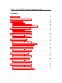
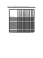
Depending upon what features from CML you would in particular like to examine
Table 1 may also give you a hint about the best examples for you to explore. Note
that there is a tendency that the simpler examples are provided first so if you are
entirely new to CML (and to its ancestors VDM and CSP/Circus) it is probably
advisable to start from the beginning. For some of the examples it is possible to
adjust it to explore more of the features from the Symphony tool. In those cases
one can see the unsupported constructs, for example, from the model checker and
the theorem prover. Their compatibility is checked automatically and warnings
for the unsupported constructs signalled in the main editor window. In some cases
such simpler examples are directly made available in the importable collection of
CML examples.
7
x
x
x
x
x
x
x
x
x
x
x
x
x
x
x
x
x
x
x
x
Table 1: Overview of characteristics for CML models
8
Time
x
x
x
x
x
x
x
x
Parameterised processes
x
x
x
x
x
x
x
x
x
x
x
x
x
x
Recursive processes
Invariants
Sequence types
Mapping types
x
x
x
x
x
x
Actions
x
x
x
x
x
x
Basic processes
x
x
x
x
x
x
x
x
Set types
CML model(s)
Stack
Incubation Monitor
Bit Register
Simple Airport Control
Incubator Monitoring
Incubator Control
Patient Register
Process Manager
Dining Philosophers
Library
Mini Mondex
Turn Indicator
Device Discovery
Leadership Election
Basic data types
D31.3d - The COMPASS Examples Compendium (Public)
x
x
x
x
D31.3d - The COMPASS Examples Compendium (Public)
2
Getting the Example Compendium
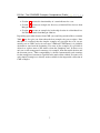
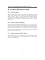
The examples described in the following sections are available for download into
the Symphony tool. To make most of the examples they should be downloaded and
tried out in the tool. Having installed the tool as described in the Symphony User
Manual, the examples are available by means of a the standard import dialogue
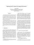
under the category “Symphony” (See Fig. 1). After pressing the button “Next”
follow the instructions to import those examples you wish to look at in detail.
More details about importing existing projects can be found in the Symphony
User Manual.
Figure 1: Importing the Example Compendium in the Symphony Tool
9
D31.3d - The COMPASS Examples Compendium (Public)
3
3.1
The Stack Example
Case Description
The basic stack example is shown in virtually every notation. Initially, the stack is
empty (made by the Init operation after an event starting on the init channel)
and there are Push and Pop operations that can be called and different channels
that connects the Stack process with the outside world. There is an action called
Cycle that is recursively defined.
3.2
Analysing using the Debugger
The Stack process can be debugged and it is possible to add token values
as for example “mk token(42)”. Here the natural behaviour of the stack can
be exercised. Note that you can also set breakpoints and inspect the different
variables when the simulation is stopped at such breakpoints.
3.3
Potential Adjustments for Experimentation
The current version of the Stack does not have an upper limit on its size. You
can try to modify it correspondingly. This can be done by introducing an invariant
on stack and an extra guard in the Cycle action when pushing a new element.
Then you can see what effects that has on the debugger and on the proof obligations generated.
10
D31.3d - The COMPASS Examples Compendium (Public)
4
4.1
The Incubator Monitor Example
Case Description
The basic incubation monitor example is simply a device that continually monitors a temperature that either can be increased with an Increment operation
or decreased with a Decrement operation. This example illustrate the use of
guards since there is a minimum and a maximum temperature. Whenever the
inc and dec channels are used the temperature represented with the state component temp is incremented and decremented by one. Pre and post-conditions
are also incorporated in this example.
4.2
Analysing using the Debugger
The IncubatorMonitor process can be debugged but no input is expected
from the user at all (except for choosing to go up or down in temperature). Note
that you also can set breakpoints and inspect the temp variable when the simulation is stopped at such breakpoints.
11
D31.3d - The COMPASS Examples Compendium (Public)
5
5.1
The Incubator Controller Example
Case Description
The basic incubation controller example is simply a device that continually monitors and controls a temperature that either can be increased with an Increment
operation or decreased with a Decrement operation. This example illustrate
the use of guards since there is a minimum and a maximum temperature. Whenever the inc and dec channels are used the temperature represented with the
state component temp is incremented and decremented by one. Pre and postconditions are also incorporated in this example.
5.2
Analysing using the Debugger
The IncubatorController process can be debugged but no input is expected from the user at all (except for chosing to go up or down in temperature).
Note that you also can set breakpoints and inspect the temp variable when the
simulation is stopped at such breakpoints. Note also that it is easy to reach a
deadlock by giving a value outside the state invariant. Try it and find out how to
repair this.
12
D31.3d - The COMPASS Examples Compendium (Public)
6
6.1
The Bit Register Example
Case Description
This simple bit register example has been provided in VDM by a student called
Andreas Müller from Austria. It has been translated to CML by Jim Woodcock
and used for testing the Symphony tool.
This example defines the main operators you can conduct on a very simple calculator where you can have registers you can store and load values to and from, and
then add and subtract. Note that it only handles bytes up to 255 so it is possible to
see the effect of overflows and underflows.
6.2
Analysing using the Debugger
Just like for the Stack example the RegisterProc process can be debugged
and it is possible to load values into the register and try to add and subtract them
from each other. Here the natural behaviour of the bit register (including underflow and overflow scenarios) can be exercised. Note that you also can set breakpoints and inspect the different variables when the simulation is stopped at such
breakpoints.
6.3
Potential Adjustments to Experiment with
In the current version there are a number of proof obligations generated that you
will not be able to discharge. Please update the argument types for some of the
operations so this can be improved.
6.4
Analysing using the Model Checker
To analyse the bit register with the model checker one currently needs to set the
maximum value for bytes to be 16 and the initial value to be 15 (due to the performance of FORMULA). The CML model that can be analysed by the model
checker is presented in the Simpler-BitRegister project. This both limits
the size for MAX as well as excluding the pre- and post-conditions at the moment.
13
D31.3d - The COMPASS Examples Compendium (Public)
7
7.1
The Simple Airport Control Example
Case Description
This example originally came from [CK04] in a VDM-SL setting. It has been
translated to CML by Jim Woodcock. This small example illustrates the logic behind granting permissions for landings and takeoffs on an airport. This is made at
a very abstract level, but it illustrates how success and failure of operations
can be signalled over dedicated channels for this. The operations in this version
of the model are made in an explicit style, whereas the original model was made
implicitly with pre and post-conditions. In a later version of the interpreter from
Symphony we expect to be able to use the implicit style and still interpret it.
7.2
Analysing using the Debugger
Just like for the Stack and the BitRegister example the Airport process
can be debugged and it is possible to experiment with different scenarios giving permissions for landing specific aircraft and registering the landed ones in a
specific airport. Note that you also can set breakpoints and inspect the different
variables when the simulation is stopped at such breakpoints.
14
D31.3d - The COMPASS Examples Compendium (Public)
8
8.1
The Patient Register Example
Case Description
This example originally came from [CK04] in a VDM-SL setting. It has been
translated to CML by Jim Woodcock. This small example illustrates the logic
behind registering patients with unique identification at a hospital. This is made at
a very abstract level, but it illustrates how success and failure of operations
can be signalled over dedicated channels for this. The operations in this version
of the model are made in an explicit style, whereas the original model was made
implicitly with pre and post-conditions. In a later version of the interpreter from
Symphony we expect to be able to use the implicit style and still interpret it.
8.2
Analysing using the Debugger
Just like for the other example the PatientRegister process can be debugged
and it is possible to experiment with different scenarios registering and removing
patients. Note that you also can set breakpoints and inspect the different variables
when the simulation stopped at such breakpoints.
15
D31.3d - The COMPASS Examples Compendium (Public)
9
9.1
The Process Manager Example
Case Description
This example originally came from [CK04] in a VDM-SL setting. This is essentially a scheduler for a multitasking operating system. Processes are identified
by a unique identification. When a process is created it joins a list of waiting
processes and will initially be in a <READY> state.
9.2
Analysing using the Debugger
Just like for the other examples presented above the ProcessManager process can be debugged and it is possible to experiment with different possibilities.
Note that this example is using indexing over the admitted processes. Thus it is
relatively easy to create a deadlock situation here.
16
D31.3d - The COMPASS Examples Compendium (Public)
10
10.1
The Dining Philosophers Example
Case Description
This is a classical computer science example for the synchronisation in concurrent
systems. In this particular version we simply have two dining philosophers for
illustration purposes. This is a very short example where the philosophers and
the forks are not synchronised, so this illustrates how one can get a deadlock
situation. This can be illustrated both using the interpreter as well as by using the
model checker.
10.2
Analysing using the Debugger
Just like for the other examples presented above the Dphils process can be debugged and it is possible to experiment with different scenarios enabling philosophers to pick up different forks and eat using different channels for getting a fork,
eating and putting a fork down again. It is possible to redefine this example in
a more generic fashion indexing over the different philosophers and the different
forks defined as their own processes.
10.3
Analysing using the Model Checker
The dining philosophers can be directly analysed without modifications. The processes are not parametrised to avoid using expressions (such as increment and
modulus) on communications.
17
D31.3d - The COMPASS Examples Compendium (Public)
11
The Dwarf Example
11.1
Case Description
This CML model has been developed jointly by Peter Gorm Larsen and Jim
Woodcock; it is inspired by the Dwarf Signal control system described by Marcus
Montigel, Alcatel Austria AG. This model is based on a VDM model made by
Peter Gorm Larsen and a CSP model made by Jim Woodcock, both have been
presented at a FM Railway workshop. Dwarf signals are mounted along railway
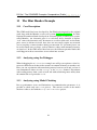
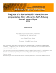
tracks and give indications to the train drivers about when they are allowed to proceed or need to stop. The lights giving the signal for the drivers looks as sketched
in Figure 2. If lights L1 and L2 are turned on it means stop, if L2 and L3 are
turned on it means drive, while a warning signal is shown by L1 and L3 being
turned on (in this case the driver needs to proceed with great care).
Figure 2: A small dwarf light with three different lights
Different safety requirements can be formulated as:
• Only one lamp may be changed at once
• All three lamps must never be on concurrently
• The signal must never be dark except if the dark aspect has to be shown or
there is lamp failure
• The change to and from dark is allowed only from stop and to stop.
Below you can see how such requirements can be analysed using the CML tool
support.
18
D31.3d - The COMPASS Examples Compendium (Public)
11.2
Analysing using the Debugger
The Dwarf model includes four different tests that one can try to experiment
with in the debugger. If you use TEST1 you can step through the TEST1 action step by step and potentially incorporate additional tock steps moving the
time at any point of time after init. In addition it is possible to shine the
dw.currentstate. Trying to violate the safety requirements mentioned above
can be experimented with using some of the other TEST’s. In these cases the preconditions will be violated and a run-time error will be issued.
11.3
Analysing using Proof Obligations and Theorem Proving
The theorem prover plugin allows the generation of an Isabelle theory for the
Dwarf model. Using the Isabelle perspective, model-based theorems may be
stated and discharged with the cml auto tac proof tactic. Such theorems include checking that an initialised state of the signal satisfies the safety invariants,
for example:
lemma NeverShowAll_Init:
"|NeverShowAll(mk_DwarfType(&stop,&stop,{},{},&stop,&stop))|
= |true|"
by (cml_auto_tac)
The proof obligation generator produces four Operation Postcondition
proof obligations. These relate to the correctness of the operation body with respect to the operation bodies. At present these can not yet be automatically discharged.
19
D31.3d - The COMPASS Examples Compendium (Public)
12
12.1
The Library Example
Case Description
This CML model has been developed by Peter Gorm Larsen and Jim Woodcock.
This is a classic standard example that has been treated by a large collection of
formal methods [Win88]. The informal requirements tackled by the different notations was formulated as follows:
Consider a small library database with the following transactions:
1. Checkout a copy of a book / Return a copy of a book;
2. Add a copy of a book to the library / Remove a copy of a book
from the library;
3. Get the list of books by a particular author or in a particular
subject area;
4. Find out the list of books currently checked out by a particular
borrower;
5. Find out what borrower last checked out a particular copy of a
book.
There are two types of users: staff users and ordinary borrowers.
Transactions 1, 2, 4, and 5 are restricted to staff users, except that
ordinary borrowers can perform transaction 4 to find out the list of
books currently borrowed by themselves. The database must also satisfy the following constraints:
1. All copies in the library must be available for check out or be
checked out.
2. No copy of the book may be both available and checked out at
the same time.
3. A borrower may not have more than a predefined number of
books checked out at one time
As such the model presented here does not present any new findings, but it is used
to illutrate how it can be formulated using CML.
20
D31.3d - The COMPASS Examples Compendium (Public)
12.2
Analysing using the Debugger
When debugging the Library example one need to choose the LibraryProcess
and then one can experiment with borrowing a book on the borrow channel, renewing a book on the renew channel, returning a book on the retBook channel,
finding a book on the find channel or finding out how many book a particular
user has borrowed using the loans channel. One can play with different scenarios here.
21
D31.3d - The COMPASS Examples Compendium (Public)
13
13.1
The Mini Mondex Example
Case Description
This CML model has been developed by Jim Woodcock inspired by the original
work done with the Mondex secure card system [SCW00, WSC+ 08]. In 1994,
National Westminster Bank developed an electronic purse (or smart card) system,
called Mondex. An electronic purse is a card-sized device intended to replace
“real” coins with electronic cash. In contrast to a credit or debit card, an electronic
purse stores its balance in itself, thus does not necessarily require any network
access to update a remote database during a transaction. So, electronic purses can
be used in small stores or shops, such as bakeries, where small amounts of money
are involved. In the CML model here however, the different potential faults that
could happen in these transactions are not taken into account.
13.2
Analysing using the Debugger
When debugging the MiniMondex example one will get an option to select between ten different cards that wish to transfer an amount of money to another card.
Here you can experiment with transferring money between cards and see how it
can communicate either over the accept or the reject channel. Experiment
with sending money from a card to itself and with transferring more money than
the amount left on a particular Card.
13.3
Analysing using Model Checking
Due to performance issues and limitations on communication parameters, it is
possible to check only one Card process. The current version of the model
checker is able to deal with the SimpleMiniMondex project.
22
D31.3d - The COMPASS Examples Compendium (Public)
14
The Turn Indicator Example
14.1
Case Description
The CML model has been developed by Jan Peleska and Uwe Schulze, and it
is inspired by collaborative work that has been done together with Daimler also
using SysML and automating testing using RT Tester [Pel02, BPS12].
The model is a simplified version of a controller in a car responsible for turn
indication flashing and emergency flashing, and the interactions between these
two actions. The controller reacts to three external inputs:
• TurnIndLvr: The turn indication lever with allowed values <neutral>,
<left> and <right>;
• EmerFlash: A button to command Emergency Flashing with the states
true = pressed = emergency flashing active and false = released = emergency flashing inactive.
• Voltage: The voltage available from the power source of the car. Values between 103 and 140 represent a value between 10.3 and 14 volt and
are acceptable for flashing. In case of lower or higher values flashing is
disabled.
The controller sends indications to the rest of the car through the channels
• FlashLeft: The value true switches the left turn indication light on and
false switches off the turn indication light.
• FlashRight: The value true switches the right turn indication light on
and false switches off the turn indication light.
The main process is composed of several actions:
• FLASH CTRL: This action on the input channels TurnIndLvr and
EmerFlash and calculates the flashing state of the system. The system can
either be not flashing at all, perform turn indication flashing or can perform
emergency flashing. This action also handles the possible overrides, e.g.
emergency flashing overriding turn indication flashing (if the emergency
switch is pressed while turn indication flashing is active) or turn indication flashing overriding emergency flashing (when turn indication flashing
is commanded while emergency flashing is active). The action uses the internal events newFlashState and newLvrState to communicate with
the other turn indication actions.
23
D31.3d - The COMPASS Examples Compendium (Public)
• OUTPUT CTRL : This action controls the actual switching of the left and
right turn indication lights. It reacts on state changes received from
FLASH CTRL through newFlashState and newLvrState to calculate which lights to switch on or off. The current voltage is received from
the action VOLTAGE through the channel newVoltage and is used to
check if the voltage is acceptable for flashing or not. If any flashing is
to be performed, this action controls the length of the flashing periods and
also provides tip flashing functionality.
• SWITCH OFF and NEW DIRECTION: These actions are used to interrupt
OUTPUT CTRL whenever during active flashing the voltage is not acceptable anymore or the turn indication lever state changes. The internal events
switchOff and newDirection are used to communicate these situations.
• VOLTAGE: This simple action receives new voltage values from the environment and communicates them to the other turn indication actions using
the channel newVoltage.
• TIMER: This action implements two timers (Timer220 and Timer340)
with set and elapsed events that are used by OUTPUT CTRL to model on
and off the flashing periods.
14.2
Analysing using the Debugger
The process TurnIndCtrlProcess can be debugged and the system can be
stimulated to turn indication flashing or emergency flashing. Every execution of
the model should start with an initialisation trace
[FlashLeft.false,
FlashRight.false,
newLvrState.<neutral>,
newFlashState.mk_FlashState(false, false, 0)]
initialising the flashing outputs. The initial values for the flash states are already
defined in the model. After the model is initialised, new values for the voltage, the
turn indication lever state or the emergency switch state can be stimulated through
the channels TurnIndLvr, EmerFlash and Voltage.
Note that the timer process TIMER in the current version of the model only waits
for 2 tock events (Timer220) or 3 tock events (Timer340) instead of 220
respectively 340 tock events. With the original values, a lot of tock events
24
D31.3d - The COMPASS Examples Compendium (Public)
would have to be performed manually when debugging the flashing cycles.
25
D31.3d - The COMPASS Examples Compendium (Public)
15
The AV Device Discovery Example
15.1
Case Description
This Device Discovery CML model represents some SoS aspects of the control
layer (CL) part of the B&O AV Architecture. The CL is the top layer, with which
the user interacts using a local control interface (hence the term control layer).
The CL part of the AV Architecture has the following responsibilities:
• Responsible for device discovery and device management
• Responsible for service discovery and service management
• Responsible for connectivity between remote and local services
• Responsible for event propagation between local and remote services
The Device Discovery model represents the communication protocols between
the announcement- and discovery processes in an IP network. Device Discovery
(DD) refers to the process of identifying devices present on a network. The DD
abstraction contains two logical mechanisms and processes:
• Device Announcement Mechanism (DAM)
• Device Discovery Mechanism (DDM (uses DAM))
The Device Discovery model has three main CML processes.
• The SourceProduct DD SD InterfaceProtocolView process models the device announcement protocol for a B&O AV source product.
• The TargetProduct DD SD InterfaceProtocolView process models the device discovery protocol for a B&O AV Target product.
• The Beo DD SD InterfaceProtocolViews process models the AV
SoS containing the product processes in an IP network.
The CML processes in the model are based on the Interface Protocol View (PDV)
from the COMPASS Interface pattern D22.3 [PHP+ 13]. In the model each CML
process represents one PDV and one PDV represent an AV Control Layer product role (source- or target role D21.4 [HPH+ 13]). In the model both product
roles can be powered on or off by events on their control layer channel. The
“SourceProductPowerchannel” and “TargetProductPowerchannel”
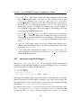
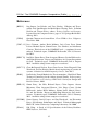
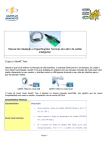
in the PDVs represents these events. The Source product’s SysML PDV state machine diagram, which the CML PDV are translated from is showed in Figure 3.
26
D31.3d - The COMPASS Examples Compendium (Public)
SysML states are translated to CML actions post-fixed with state in their action
name.
Figure 3: Source product SysML state machine
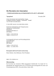
In the model products communicate using the IPMulticastChannel channel. The IPMulticastChannel represents the IP transport layer logic. In the
PDVs we simulate the asynchronous behaviour of the IP multicast logic by using
CML timeouts for breaking channel synchronisation between the processes. Note
that at any time during announcement and query operations states, the products
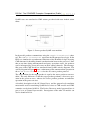
can be interrupted by power-off events on their control channels. The interruptible parts of the CML model are translated from SysML activity diagrams. The
activity diagram in Figure 4 shows a refinement of the announcement operation in
the DD SD Announcement State for the AV source product protocol.
The state machine for the target product is equal to the source products state machine. The only difference is that the target product performs a discovery operation in the power-on state, whereas the source product performs an announce
operation in the power on state.
A detailed description of the AV Control layer, and the pattern-level translation
meta-model used for translating SysML based views to CML models and CML
semantics can be found in D21.4. The Device Discovery model presented here is
part of a set of Control layer models. Descriptions of the other CL models can
also be found in D21.4.
27
D31.3d - The COMPASS Examples Compendium (Public)
Figure 4: Refinement of the announcement operation
15.2
Current Model limitations and Bugs
The target product model does not simulate the device management consistency
part of the DD protocol. The device management will be added later.
The processes control statements do not use the VDM pre function option.
This is currently not working correct in the tool. For now the model uses Boolean
helper functions for conditional checks.
The IP transport layer should be modelled as a separate process, enabling product
scalability of the SoS.
Currently inspection of variables values is not working on windows
15.3
Analysing using the Debugger
The Device Discovery model contains some test processes you can perform. Launch
the Beo DD SD InterfaceProtocolViews process.
The first thing you need to do is to power on the products in the network. Click on
28
D31.3d - The COMPASS Examples Compendium (Public)
the SourceProductPowerChannel.<POWER ON> and TargetProductPowerChannel.<POWER ON> events in the debugger’s event option windows.
Now both products start their announcement and discovery logic. You now have
the following options:
• To simulate a multicast time-out, click tock twice for the process you wish
to time-out.
• To let the target product discover the source product, click the IPMulticastChannel.2 options in the CML event option window. You can verify this by looking at the values in the product DRs set in the
TargetProduct DD SD InterfaceProtocolView process. The set
should now contain the value 2.
Once the source product has been discovered, it should not be discovered again.
Test this by adding a break point in the updateProductSet operation in the
TargetProduct DD SD InterfaceProtocolView process. This break
point should never be hit after the product has been found once.
Try during execution of the models to interrupt the processes protocol actions by
firing the SourceProductPowerChannel.<POWER OFF> or the
TargetProductPowerChannel.<POWER OFF> event.
Shut down the SoS debug by killing the Debugger process pressing the red box.
For getting a better understanding of the products protocol semantics, run the
SourceProduct DD SD InterfaceProtocolView
or
the
TargetProduct DD SD InterfaceProtocolView process by itself.
Click on the events offered by the CML event option window, and observe the
simulated Device Discovery semantics.
You can also run the Test 1 process and just click on the event offered to you in
the CML event option window.
15.4
Analysing using Model Checking
Except for the processes using set manipulation, all other processes can be analysed in the model checker. Simplifications were performed such as replacement of mu construct with explicit recursive processes, time information was
removed and types had to be limited to a finite set. This is represented in the
Simple-AVDeviceDiscovery project.
29
D31.3d - The COMPASS Examples Compendium (Public)
16
The Leadership Election Example
16.1
Case Description
A Bang & Olufsen (B&O) home Audio/Video (AV) network consists of several
devices (such as audio, video, gateway and legacy audio products) which may be
produced by competing manufacturers and distributed across a user’s home. Such
a network is an SoS: it exhibits the dimensions typical of an SoS as described in
[NLF+ 13]. Constituent systems may join or leave the network at any time, but a
consistent user experience (such as a playlist, current song, etc.) must be provided,
and this requires availability and consistency of the system configuration data.
In order to do this, a publish/subscribe architecture is employed. This in turn,
requires that the underlying network is able to elect a leader from among the
CSs. As there is no centralised control, the ability to elect a leader is a required
emergent property of the SoS.
The leadership election (LE) problem is a distributed consensus problem in a network with unreliable processes and asynchronous communication. When the CSs
of the network are in an election state, no publisher is present and the multi-room
experience space is inconsistent and unavailable. During the election, the devices
must react to a set of local transition rules that will guarantee the desired emergent
property of a leader in the network, and allow the network to enter the publishersubscriber state.
The Emergent Leadership model has three main CML processes.
• The Node process models the LE devices behaviour in the network.
• The Transport layer process models the network layer and network protocols behaviour.
• The SoS Election process models the SoS level behaviour by combining a
set of node processes and the transport layer process.
Each LE device may be in one of the states Leader, Follower or Undecided.
After initialisation, a LE Device enters the Off state. From here, it may be turned
on and it enters a parallel state with two sub-states: the Listener and Election
states. In the Listener state, the LE Device repeatedly receives messages from
its environment and performs the update operation. In the Election state, the LE
Device initially enters the Undecided state, where it updates its claim to be undecided. After some time, the LE Device queries its updated attributes (these
30
D31.3d - The COMPASS Examples Compendium (Public)
are updated in the Listener state), and decides if it can be a leader on the network.
If the LE Device can be a leader, it enters the Leader state, updates its claim and
sends a message to all other devices it knows about. From this state, the LE Device
continuously checks if it may be a leader. If, after becoming a leader, it receives a
message from an existing leader, the LE Device enters the Undecided state. If the
LE Device may remain a leader, then it increases its strength of the claim to be a
leader and again sends a message to all other devices. Allowing successful leaders
to increase the strength of their claim is a heuristic to increase the likelihood of
successful leaders remaining as leaders, and thereby reduce the number of new
elections.
If the LE Device is not a leader, it enters the Follower state. Once in this state, the
LE Device updates its claim to be a follower sends a message to all other devices.
Once a LE Device is a follower, it remains in the Follower state unless either there
are no leaders, or there is another LE Device claiming to be leader.
16.2
Current Model limitations and errors
The predicate logic regarding strength calculations need to be improved.
The model has two version of the amLeader operation; this is because of a bug in
the interpreter, which currently not allows an action calling the same operations
twice.
Remove the debug events.
16.2.1
Analysing using the Debugger
The following debug steps cover are analysing these leadership specifications
• Node joins empty network
– Excepted result
∗ The node becomes the leader
• Node joins network which has a leader
– Excepted result
∗ The newly joined node becomes a follower.
31
D31.3d - The COMPASS Examples Compendium (Public)
• Leader leaves network
– Excepted result
∗ The follower becomes leader.
The process you want to run in the debugger mode is the SoS Election process.
Lunch the process from the process option window ,this will take you to the debug
view First you need to init the network layer process and the node processes. Click
init in the event option window. The next steps will test the Node joins empty
network specification against the model.
The event option window will now give you the option to turn the nodes in the
network on. Click on node 0, this will result in node 0 enter the network in the
Undecided state. In this state the node will to see if where a leader in the network
is.
Node 0 is communication with the transport layer, but since where are no other
node in the network the communication will time out, simulate that be clicking on
the tock event in the event option window 4 times.
In the event option window you will now see some “debug” info, saying the
highest_is.0.1, meaning node 0 with strength 1 is the leader. Click on this
and move on.
You will now get another debug event saying
leaderClaim.0.true, this meant the node 0 has the leadership claim. Just
click on the event and move on. Now you can see that node 0 is broadcasting to the
network it’s leader ship claim. The event n_send.0.1.mk_CS(<leader>,0)
means node 0 is sending to node 1, that node 0 is the leader with strength 1. We
have now finished the steps for the Node joins empty network specification. Now
let do the steps for the Node joins network which has a leader specification.
Turn on node 1 from the event option window. Node 1 is now in the Undecided
state and will read from the network. Press the events in this order.
• n_send.0.1.mk_CS(<leader>, 0), means node 0 sends to node 1
• n_rec.1.0.mk_CS(<leader>, 0), means node 1 receive data from
node 0
• n_send.0.2.mk_CS(<leader>, 0), node 0 try to send to node 2
• n_rec.0.2.10, node 0 gets a time-out from the transport layer, trying to
communicate with node 2
That happens now is that node 1 is a follower and node 0 is still the leader. The
follower is now listening to the leader, and the leader is broadcasting its leader
claim. The leader it also listening to the network, so the first event options you
32
D31.3d - The COMPASS Examples Compendium (Public)
gets after the communication trances showed above are the leader (node 0) trying
to read from the network. So you need to time him out, since nobody else is
sending. Do that by clicking tock 4 times.
Now you will get a set of debug events, saying how is the leader. Click the debug
event in this order.
• highest_is.0.1
• highest_is.1.0
• leaderClaim.0.true,means node 0 say am the leader
• leaderClaim.1.false, means node 1 say am not the leader
So now we have a leader and a follower, we can see node 0 is sending its leadership
claim to the network by offing these events
• n_send.0.1.mk_CS(<leader>, 0), means node 0 sends to node 1
• n_send.0.2.mk_CS(<leader>, 0), node o try to send to node 2
We have now completed the steps for Node joins network which has a leader specification, so let us do the steps for the Leader leaves network specification.
To get the leader to leave the network click on the off.0 event in the event
option window. The follower node 1 will now discover the leader is gone and go
to the Undecided state. In this state the node will read from the network, to see
determine how should be the leader since nobody else is sending data, timeout
node 1 by clicking on tock 4 times. You will now get the following debug event
options. Click then in the order
• highest_is.1.0, mean node 1 is the leader
• leaderClaim.1.true
You will now see that Node 1 is broadcasting its leader claim to the network via
these events
• n_send.1.0.mk_CS(<leader>, 0)
• n_send.1.2.mk_CS(<leader>, 0)]
This completed the steps for the Leader leaves network specification and whereby
this example, close down the SoS by clicking on the deInit event. In the model
where are some automatic test you can run. The TestLeaderNode process is a test
case for the Node joins empty network specification. The process contains a set
of legal trances, witch test the SoS election process. Try running the test process
in the simulate mode, and then set a breakpoint in the sendCS action. If you now
33
D31.3d - The COMPASS Examples Compendium (Public)
look in the variable view for node 0’s call stack. You can see that node 0 has no
leaders, meaning node 0 is the leader.
34
D31.3d - The COMPASS Examples Compendium (Public)
References
[BPS12]
Jörg Brauer, Jan Peleska, and Uwe Schulze. Efficient and Trustworthy Tool Qualification for Model-Based Testing Tools. In Brian
Nielsen and Carsten Weise, editors, Testing Software and Systems,
Lecture Notes in Computer Science, pages 8–23. Springer Berlin Heidelberg, 2012.
[CK04]
Quentin Charatan and Aaron Kans. From VDM to Java. Palgrave,
New York, 2004.
[CMC+ 13] Joey Coleman, Anders Kaels Malmos, Luis Couto, Peter Gorm
Larsen, Richard Payne, Simon Foster, Uwe Schulze, and Adalberto
Cajueiro. Third release of the COMPASS tool — symphony ide user
manual. Technical report, COMPASS Deliverable, D31.3a, December 2013.
[HPH+ 13] Jon Holt, Simon Perry, Finn Overgaard Hansen, Stefan Hallerstede,
and Klaus Kristensen. Report on Guidelines for System Integration
for SoS. Technical report, COMPASS Deliverable, D21.4, August
2013. Available at http://www.compass-research.eu/.
[NLF+ 13] Claus Ballegaard Nielsen, Peter Gorm Larsen, John Fitzgerald, Jim
Woodcock, and Jan Peleska. Model-based engineering of systems of
systems. Submitted to ACM Computing Surveys, June 2013.
[Pel02]
Jan Peleska. Formal Methods for Test Automation – Hard Real-Time
Testing of Controllers for the Airbus Aircraft Family. In Integrating
Design and Process Technology, IDPT-2002. Society for Design and
Process Science, 2002.
[PHP+ 13] Simon Perry, Jon Holt, Richard Payne, Claire Ingram, Alvaro
Miyazawa, Finn Overgaard Hansen, Luı́s Diogo Couto, Stefan
Hallerstede, Anders Kaels Malmos, Juliano Iyoda, Marcio Cornelio, and Jan Peleska. Report on Modelling Patterns for SoS Architectures. Technical report, COMPASS Deliverable, D22.3, February
2013. Available at http://www.compass-research.eu/.
[SCW00]
Susan Stepney, David Cooper, and Jim Woodcock. An Electronic
Purse: Specification, Refinement, and Proof. Technical Monograph
PRG-126, Oxford University Computing Laboratory, Jul. 2000.
[Win88]
J.M. Wing. A Study of 12 Specifications of the Library Problem.
IEEE Software, Juli 1988.
35
D31.3d - The COMPASS Examples Compendium (Public)
[WSC+ 08] Jim Woodcock, Susan Stepney, David Cooper, John A. Clark, and
Jeremy Jacob. The Certification of the Mondex Electronic Purse to
ITSEC Level E6. Formal Aspects of Computing, 20(1):5–19, 2008.
36