1
Please check the following hyperlink to get the latest version of this user manual.
http://www.hobbywing.com/download.asp?id=5
FEATURES
► Specially designed for 1/12th on-road competition, the electronic switch, capacitor
module and DC/DC booster are all built-in, save space on chassis.
► Same Factory Pre-set Profiles as XERUN-120A-V3.1 (2-3S version). Up to ten profiles
can be stored in the memory and imported or exported easily. Factory pre-set profiles
include Blinky mode, Modify Mode, Stock mode, Practice mode, Offroad mode, etc.
► Aluminum Upper and Bottom Case with optional colors, giving better heat dissipation,
and allowing higher current.
► External Programming Port (EPP), easy to connect and also a power port for additional
fan.
► Advanced Dynamic Timing technology, providing more customization possibilities for
highest level competitions.
► Multi Protection Functions such as ESC and motor overheat protection, low voltage
cutoff protection and throttle signal loss protection etc make the running safe.
► Precise throttle and brake control, setting of drag brake and brake strength with more
options, new punch and brake rate control functions, throttle cure and brake curve
through the PC client.
► Integrated Data logger, recording the maximum temperature of ESC and motor as well
as the maximum RPM. All running data is easy to be checked by using LCD Programming
Box.
► New USB LINK Software graphic interface, providing extra parameters for advanced
settings.
► Compatible with the portable LCD Programming Box, easy to set the ESC and upgrade
the firmware by connecting PC.
SPECIFICATIONS
Model
XERUN-120A-1S-V3.1
Cont./ Burst Current
Motor Type Supported
120A / 830A
Sensored and Sensorless Brushless Motors
Cars Applicable
1/12 On-road cars
Motor
Llimit
1cell Lipo or 3 cells NiMH
Resistance
Voltage Input
0.00026 ohm
3.0-5.76V(1 cell Lipo or 3-4 cells NiMH)
Attention! This ESC cannot work with 2S Lipo or NiMH ≥ 5 celss NiMH
BEC
Footprint
6V@3A switch mode BEC with built-in DC/DC booster
37.5mm x 31mm
Height
21.8mm
37.8g
Weight (excl. wires)
FAN
External Programming Port Output
03
≥3.0T
(For 3 slots, 2 poles 540 motor with zero timing of the ESC)
Not available
6V voltage from built-in BEC, usable for external cooling fan
WWW.HOBBYWING.COM
FIRST USE OF A NEW ESC
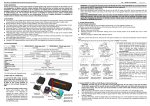
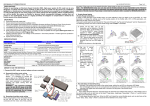
1. Connect the ESC, motor, receiver, battery and servo correctly, as in the Figure 2
(Page1). Never plug in the power wire of ESC to the wrong polarity of battery, it
will seriously damage the ESC.
a) Sensored brushless motor wiring
When using brushless motor with Hall Sensor, it is necessary to connect the sensor
cable to the “SENSOR” socket on the ESC. The ESC can automatically identify the motor
type (sensored or sensorless) by detecting the signal coming from the SENSOR socket.
WARNING! For sensored brushless motor, the #A, #B, #C wires of the ESC
MUST be connected with the motor wire #A, #B, #C respectively. Do not change
the wires sequence!
b) Sensorless brushless motor wiring
When using brushless motor without Hall Sensor, the #A, #B, #C wires of the ESC can be
connected with the motor wires freely (without any order). If the motor runs in the
opposite direction, please swap any two wire connections.
Note: For SENSORLESS motor, you can also set the throttle channel of your
transmitter to the REVERSE direction, and then the motor will run oppositely. You will
need to calibrate the throttle range again after changing the direction of throttle
channel. Please keep in mind that this method is ONLY available for SENSORLESS motor.
2. Throttle Range Setting
(Throttle Range Calibration)
In order to match the ESC to your transmitters throttle range, you must calibrate it before
use.
Calibration must be performed after any of the following, otherwise the ESC will not work
properly;
►Before the first run of a new ESC.
►Before using a new transmitter.
►Following changes to the transmitter settings such as the neutral position of the
throttle stick, ATV or EPA parameters, etc.
►Following changes to different ESC software versions.
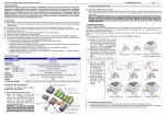
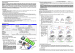
There are 3 points that need to be set. They are the “Top point of forward”, the “Top point
of backward” and the “Neutral point”.The Figure 3 and Figure 4 (Page2) show how to set
the throttle range with a FutabaTM transmitter.
A) Switch off the ESC, turn on the transmitter, set the direction of throttle channel to
”REV”, set the throttle trim to “0”, set the “EPA/ATV” value of throttle and brake channels
to “100%”, and disable any ABS function on your transmitter.
B) Hold the switch button for 2 seconds until the red LED begins to flash. Release the
switch button.
C) Set the 3 points correctly, as in the Figure 4 (Page2).
With the transmitter at neutral point, press the switch once. The green LED flashes once
and the motor sounds "Beep" once.
04