1
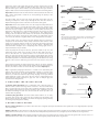
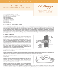
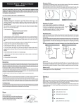
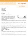
L
.
R
.
B
A
E L E M E N T
A C T I V E
INSTALLATION
MANUAL
&
G
G
S
P
I
C
K
U
P
S
S YS T E M
USER'S
GUIDE
4 8 3
N .
F R O N T A G E
N I P O M O ,
C A
R D .
9 3 4 4 4
W W W . L R B A G G S . C O M
TA B LE
OF
CONT ENTS
1. Package contents
2. Overview and cautions
3. Strapjack/preamp installation
4. Pickup Installation
5. Finishing the installation
6. Other applications
1.PACK AGE
CONT ENTS
One (1) Element Active System with undersaddle pickup, endpin preamp and volume control pre-attached
One (1) Battery Bag
Three (3) self-stick wire clips
2.OVE RVI E W
AND
C AUT IONS
The Element Active System combines Element undersaddle pickup with a pre-contoured, all-discrete class A endpin preamp. A soundholemounted volume control gives you additional control and versatility without having to drill any holes in your instrument. The Element Active is
designed to interface with just about anything you plug into, but best results will be achieved with a high-quality, full-range P.A. Plugging in and
unplugging the cord will turn the preamp on and off.
We recommend that this system be installed by a professional dealer/installer. We do not provide installation advice or support for home or
hobbyist installations. Installers: please read the instructions carefully before proceeding. We will not be responsible for any damage to the guitar
or personal injury resulting from installa-tion, improper installation, use or misuse of the product.
3.S T R A PJ ACK /PR EAMP
INSTAL L ATI O N
Drilling the strapjack hole: For proper installation, this jack requires a clean
1/2" hole in the tail block of the instrument. If the guitar lacks this hole, start
by placing a piece of masking tape on the outside of the instrument over the
drilling area (to avoid chipping the finish), drill a small pilot hole in the tail
block and then follow with a step drill.
Installing the strapjack: Remove the strap ring, retaining nut and one
washer from the end of the jack. There should still be one star locking washer,
one flat washer and a nut remaining on the jack. Bring the jack down through
the soundhole into the body and insert it into the pre-drilled hole in the tail
block. Using the internal nut (be sure to include the flat and star washers), set
the proper depth that will allow the entire smaller threaded section to
protrude from the instrument (see figure 1).
fig. 1
tail
block
smaller
threaded
section
protrudes
With the jack in place, lay the remaining washer over the threads and attach
the external retaining nut until it’s tight. Finish by attaching the strap ring (it
should cover the retaining nut and washer). Asserting too much pressure may
crack the finish. Now bring the preamp into the guitar (do not adhere it yet), connect a battery, and plug the strapjack cable into the "output"
socket. Then proceed to following section.
4 . P ICK UP
I NSTA LL ATI ON
Installation notes: For optimum performance of the Element, the bridge slot must have a clean, flat surface free of any debris or over-spray from
the finish. The slot must be a minimum of .125” (1/8”) deep, but we suggest a depth of at least .187" (3/16”) to avoid excessive saddle tilt.
The commonly-known 50/50 rule applies: The amount of saddle visible above the bridge surface (with pickup installed) should be no greater than
the amount of saddle in the slot beneath the bridge surface; otherwise the balance and output of the pickup may suffer.
8.2 Short saddle note: The first 1/8" of the Element pickup is not active. If you do not have a minimum of 1/4" of saddle beyond the hi-E string, you
may experience low output on this string. To remedy this, drill a small horizontal hole in the end of the slot to extend the pickup further under
the saddle (see figure 2). To drill this hole without disrupting the floor of the saddle slot, place a small jeweler's screwdriver under the tip of the
drill bit. On short saddles we also advise that the pickup exit hole be drilled into the end wall of the saddle slot rather than the slot's floor (see
figure 3) to likewise extend saddle/pickup contact at the exit end. Again use the jeweler's screwdriver to protect the saddle floor as you drill.
8.3 Installation: Remove the strings from the guitar. To duplicate the string height exactly, scribe a line along the front edge of the saddle where
it extends above the bridge. The line will later be used as a guide when removing material from the bottom of the saddle to compensate for the
thickness of the pickup (.037” total). Remove the saddle to drill the hole for the pickup. The drill bit needs to be as large as the saddle slot will
allow.
Inspect the inside of the guitar and note the position of the braces and the
iBeam in relation to the saddle slot. Drill at either end of the slot on the side
that will enable you to avoid all braces as you penetrate the top, as shown in
figure 5. Blow out the slot with compressed air and check for remaining debris.
Important: Round the inside of the hole where it meets the bottom of the slot
with a small, sharp knife or small file to avoid pinching the pickup as the
saddle lies on it.
Feed the pickup into the slot from inside the guitar with either side up.
Inserting a toothpick or similar object through the hole from the outside is
helpful in finding the location of the hole on the inside of the guitar.
Important: The fit of the saddle in the slot is the single most important factor
in this installation. It is crucial that the bottom of the slot and the lower
surface of the saddle be flat to make even contact with the pickup. The saddle
should fit loosely enough in the slot that it can be pulled out with your
fingertips. It will then have a slight forward lean when the strings are under
tension. It is absolutely necessary to compensate for this slight lean by
sanding a tilt in the bottom of the saddle so it still sits flat on the pickup when
the strings are at tension (see figure 6). If the saddle is too tight, binds at all or
is too loose, this will have a negative effect on the string balance and output.
Set the saddle in the slot, noting how much material must be removed to
compensate for the thickness of the pickup. Sand the bottom surface of the
saddle on a belt sander until the scribe line is just above the bridge top. Finish
sanding the bottom by hand. It is best to do this against a machined flat
surface with fine sandpaper. Use a straightedge with a strong light source to
inspect the flatness of your saddle.
Insert the pickup all the way into the slot, place the saddle on top of it, and
temporarily secure it with a piece of tape. Secure the wire with a wire clip as
close to the exit hole as is practical, with a one- to two-inch service loop.
Failure to secure the wire may produce boominess and feedback. Now restring
the guitar, and plug into your amp or PA. Confirm that the EQ controls are at
their default positions and test the Element, paying careful attention to string
balance. If the sound is satisfactory, proceed to the next section. If not, read
on.
fig. 2
extension
fig. 3
fig. 4
drill bit
jeweler's screwdriver
short saddle:
drill side wall
normal saddle:
drill floor
fig. 5
This view depicts the bridge at an angle that is level with the guitar
top and perpendicular to the saddle slot. Note the rounded edge
where the hole has been drilled.
drill bit
slot
bridge
guitar top
brace
String balance problems are almost always the result of an uneven interface
between the bottom of the saddle and the saddle slot. If the string balance is
uneven, check these surfaces to ensure that they are both completely flat.
fig. 6
Tip: A segmented packaging knife blade is a useful tool in determining the
flatness of the saddle slot. Break off enough blade segments so as much of the
blade fits into the slot as possible. Briefly use a back-and-forth scraping
motion to see if the slot bottom scrapes evenly. Any high or low spots will be
readily apparent. A minor low spot in the slot may be compensated for by
shims under the pickup; however, for gaps over .005" or multiple gaps, we
recommend rerouting the slot.
5 . FI NI SHI NG THE
I NSTA L L AT ION
5.1 Volume wheel placement: Find a comfortable and convenient place to
affix the volume control at the edge of the sound hole -- most users will find it
best to position the unit on the side of the soundhole that will be above the
strings when playing. Clean the desired placement area completely, peel off
the adhesive backing, and stick once. Be sure that the chosen spot does not
interfere with any bracing.
5.2 Battery Bag placement: Stick the double-sided adhesive to an easily
accessible spot inside of the guitar near the preamp. Insert the battery and
battery clip into the bag. The battery can then be changed by opening the flap
on the bag and pulling out the battery.
6 . OT HE R
proper saddle-pickup contact
(saddle lean exaggerated)
fig. 7
Element Active input (A)
+-
+aux passive input (B)
A PP LIC ATI ONS
Passive auxiliary channel: It is possible to add a mini-mic or magnetic pickup to the Element Active System. Do not use high impedance pickups
such as the iBeam.
Adding a mini-mic: To add a mini-mic, solder the hot lead to positive and the ground lead to negative of the auxiliary passive input and run both
pickup and mic down a stereo cord to a 2-channel mixer with phantom power for the mic (see figure 8). The mic will be on the ring channel.
Adding a magnetic pickup: Add a magnetic pickup the same way to the auxiliary passive channel, and run both signals down a stereo cord to a 2
channel mixer or use a stereo Y cord and two Para D.I.s. The magnetic pickup will be on the ring channel.