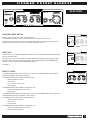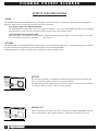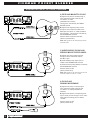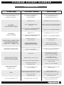
1
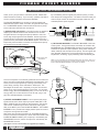
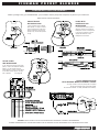
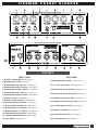
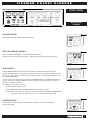
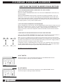
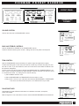
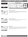
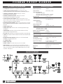
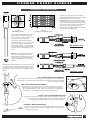
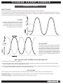
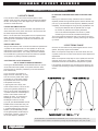
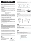
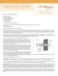
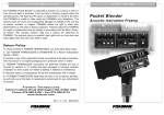
O W N E R ’ S
M A N U A L
POCKET
BLENDER
®
ACOUSTIC INSTRUMENT PREAMP
FISHMAN
POCKET
BLENDER
INTRODUCTION: THE BLENDER SYSTEM
Thank you for your purchase of a Fishman product. Please read
these instructions carefully. If you have any questions, feel free to
call our product information line at (978) 988-9665.
The POCKET BLENDER is a compact, 2-channel preamp that
addresses the specific needs of acoustic stringed instrument players. The BLENDER System combines the sounds from a pickup
and an instrument-mounted mini-microphone.
1) MICROPHONE and PICKUP: A microphone alone is capable of
capturing the natural ambience and resonance of an acoustic
stringed instrument. A single piezo pickup delivers a clear, balanced, high-output signal with low feedback. Combining the two
sounds results in tone quality and projection in which the sum is
greater than the parts. Before the BLENDER System, there was no
simple and practical means to combine a microphone and pickup
for the performing acoustic musician.
UNDER-SADDLE PIEZO
TRANSDUCER
MINI-MICROPHONE MOUNTED ON
X-BRACE NEAR SOUNDHOLE
The mini-microphone is conveniently positioned on the instrument
with a mounting clip specifically designed for the application. This
allows you the unique opportunity of having a permanent microphone setup, precisely at the instrument's "sweet spot". The
advantages of this are clear - especially to anyone who has ever
had to set up a microphone without a sound check - five minutes
before the gig! With the BLENDER System, you can now arrive at
the gig, take your mic'ed instrument out of its case, plug in and
play with complete freedom of movement.
2) STEREO INSTRUMENT CABLE: The microphone and pickup
signals are fed into a stereo output jack (also called TRS or TIP /
RING / SLEEVE) that is mounted on the instrument. The two signals are then routed through a stereo instrument cable (again,
TRS) to the INPUT jack on the POCKET BLENDER. The POCKET
BLENDER in turn provides low voltage phantom power to the minimicrophone through the same cable.
With pickup and microphone wired to TIP and RING respectively,
and your instrument connected by a stereo instrument cable to the
POCKET BLENDER's INPUT jack, the pickup is controlled by the
TRANSDUCER channel, and the microphone is controlled by the
MICROPHONE channel.
(See pages 13-14 for more information on Suggested Input Options)
2
By consolidating the two signals plus phantom power, you save
both setup time and aggravation. The stereo instrument cable provides a simple solution to the hassle of multiple cable runs and
outboard phantom power supplies.
3) THE POCKET BLENDER: The POCKET BLENDER is the brain
of the system. The signals from the instrument are routed to the
MICROPHONE and TRANSDUCER channels. Each channel is optimized for the particular input impedance, level, phase and equalization needs of both microphone and pickup. The two signals are
then "blended" together and a composite signal can be sent to
amplification, recording, signal processing and/or broadcast gear.
NOTE: If your instrument has an onboard preamp, and you want to route microphone and pickup signals through a stereo instrument cable, you may need to
install a Fishman SMART SWITCH for the system to operate.
FISHMAN
POCKET
BLENDER
PREPARING YOUR INSTRUMENT
Before you begin using your Pocket Blender, you will need to have a pickup and microphone in place on your instrument.
Here are four common scenarios:
PASSIVE PICKUP
AND MICROPHONE:
If your instrument has a passive
piezo pickup, it’s easy to connect
it and a microphone to the same
stereo endpin jack. Connect the
pickup to tip, and the microphone
to ring.
PICKUP WITH
POWERJACK AND
MICROPHONE:
If your instrument has a piezo or
magnetic pickup and a Fishman
Powerjack, connect a microphone
to the ring by soldering it to the
appropriate terminal on the
Powerjack circuit board.
ACTIVE PICKUP
AND MICROPHONE:
If your instrument has an active piezo
pickup - such as the Fishman Acoustic
Matrix - you will need a Fishman
Smart Switch to connect a microphone
to the stereo endpin jack for the system to operate.
See Page 23
PICKUP AND MICROPHONE
WITH SEPARATE MONO INSTRUMENT CABLES:
You may choose to route the pickup and microphone
through two separate mono instrument cables.
You will need a stereo "Y" cable (available from Fishman).
WARNING: INSTALLATION BY A QUALIFIED PROFESSIONAL REPAIRMAN IS STRONGLY RECOMMENDED.
FISHMAN TRANSDUCERS WILL NOT BE RESPONSIBLE FOR ANY DAMAGES TO YOUR INSTRUMENT DUE TO IMPROPER INSTALLATION.
3
FISHMAN
POCKET
CONTENTS
INTRODUCTION
...................2
PREPARING YOUR INSTRUMENT . . . . . . . 3
QUICK START . . . . . . . . . . . . . . . . . . . . . .4
FEATURES . . . . . . . . . . . . . . . . . . . . . . . .5
BLENDER
QUICK START
You don't have to read this manual to get up and running, but we
recommend that you do in order to get the most out of your
POCKET BLENDER.
Here's what you need to do if you want to "plug in and play".
COMPONENTS
1) POCKET BLENDER
2) 9 Volt Alkaline Battery
POWER
INPUT JACK . . . . . . . . . . . . . . . . . . . . . . .6
3) Pickup and mini-microphone connected to a Stereo
Jack (TRS = Tip / Ring / Sleeve) See Page 2.
4) Stereo Instrument Cable
5) XLR or 1/4" mono instrument cable.
FRONT PANEL MICROPHONE CHANNEL . . . . . . . . . . . . .7
PROCEDURE
FRONT PANEL TRANSDUCER CHANNEL . . . . . . . . . . . . .9
1) Lift the battery compartment lid on top of the POCKET
BLENDER and install a fresh 9 Volt alkaline battery.
Replace the lid.
FRONT PANEL MASTER SECTION . . . . . . . . . . . . . . . . .10
2) Connect the stereo cable to the instrument and to the INPUT
jack on the POCKET BLENDER.
REAR PANEL . . . . . . . . . . . . . . . . . . . . .11
3) Set all front panel switches to the OUT position. Set the
phantom power switch on the rear panel to the IN position.
Set both VOLUME controls fully counter-clockwise.
Set the MASTER level to 3:00. Set the BASS and TREBLE
controls to 12:00.
SUGGESTED INPUT OPTIONS . . . . . . . . .13
SUGGESTED OUTPUT OPTIONS . . . . . . .15
OUTPUTS / EFFECTS . . . . . . . . . . . . . . .16
TROUBLESHOOTING . . . . . . . . . . . . . . . .17
OPTIONAL ACCESSORIES
SPECIFICATIONS
BLOCK DIAGRAM . . . . . . . . . . . . . . . . . .18
APPENDIX I: MICROPHONE . . . . . . . . . . .19
4) Run a cable from one of the outputs on the rear panel of
the POCKET BLENDER to your amp or PA system.
5) With the POCKET BLENDER'S MASTER LEVEL at 3:00,
adjust both the MICROPHONE and TRANSDUCER VOLUME
controls to approximately the same level.
BATTERY OPERATION
Make note of the following precautions when using the POCKET
BLENDER under battery power:
The POCKET BLENDER has no ON/OFF switch. Under battery power, the POCKET BLENDER is turned on only when
the STEREO IN jack is plugged in.
Power is always on when using an AC Adapter.
See Page 6
APPENDIX II: PHASE . . . . . . . . . . . . . . . .21
To avoid excessive battery drain:
APPENDIX III: SMART SWITCH . . . . . . . .23
LIMITED WARRANTY . . . . . . . . . . . . . . . .24
a. Unplug the INPUT jack when the unit is not in use.
b. When using the POCKET BLENDER without a mini-electret
microphone, be sure the phantom power is OFF
(switch is pushed OUT).
Battery life is an estimated 60 hours continuous use.
4
FISHMAN
POCKET
BLENDER
FEATURES
FRONT PANEL
REAR PANEL
1) BATTERY COMPARTMENT ( See Page 6 )
2) MICROPHONE VOLUME ( See Page 7 )
3) MICROPHONE BASS CONTROL ( See Page 7 )
17) PHANTOM POWER SWITCH ( See Page 11 )
18) 1/4” INPUT JACK (TRS) ( See Pages 6 & 11 )
4) MICROPHONE TREBLE CONTROL ( See Page 7 )
5) TRANSDUCER VOLUME CONTROL ( See Page 9 )
6) TRANSDUCER BASS CONTROL ( See Page 9 )
19) MICROPHONE EFFECTS SEND ( See Page 11 )
20) MICROPHONE EFFECTS RETURN ( See Page 11 )
7) TRANSDUCER TREBLE CONTROL ( See Page 9 )
8) BATTERY LOW LED ( See Page 10 )
21) TRANSDUCER EFFECTS SEND ( See Page 11 )
9) MASTER VOLUME CONTROL ( See Page 10 )
10) MICROPHONE TRIM CONTROL ( See Page 7 )
11) MICROPHONE PHASE SWITCH ( See Page 7 )
22) TRANSDUCERS EFFECTS RETURN ( See Page 11 )
23) 1/4” UNBALANCED OUTPUT ( See Page 12 )
12) MICROPHONE HI CUT SWITCH ( See Page 8 )
13) MICROPHONE LO CUT SWITCH ( See Page 8 )
14) TRANSDUCER TRIM CONTROL ( See Page 9 )
24) GROUND LIFT SWITCH ( See Page 12 )
25) XLR BALANCED OUTPUT ( See Page 12 )
15) TRANSDUCER PHASE SWITCH ( See Page 9 )
16) MUTE SWITCH ( See Page 10 )
26) AC ADAPTER INPUT ( See Page 6 )
5
FISHMAN
POWER
POCKET
BLENDER
A - BATTERY POWER
Make note of the following precautions when using the POCKET BLENDER under
battery power:
The POCKET BLENDER has no ON/OFF switch. Under battery power, the POCKET
BLENDER is turned on only when the STEREO IN jack is plugged in.
Power is always on when using an AC Adapter
To avoid excessive battery drain:
a. Unplug the INPUT jack when the unit is not being used.
b. When using the POCKET BLENDER without a mini-electret microphone,
be sure the phantom power is OFF.
BATTERY COMPARTMENT
To replace the battery, lift the battery compartment lid on the top of the POCKET
BLENDER.
B - AC POWER
USE ONLY the Fishman Model-910 or the Roland PSA series Regulated AC
Adapters.
The POCKET BLENDER is turned on at all times when using an AC Adapter.
Use of the AC Adapter will prevent battery drain.
You may daisy-chain your AC Adapter in parallel with other devices as long as the
combined current draw does not exceed the milliamp output of the AC Adapter.
INPUT JACK
The INPUT jack is a TRS (Tip/Ring/Sleeve) input that can accept two discrete signals through a stereo instrument cable.
Two signals from your instrument (For example: Internal Microphone and Pickup)
are routed through a stereo instrument cable to the INPUT jack. The Ring goes to
the MICROPHONE channel and the Tip goes to the TRANSDUCER channel.
See Page 3.
6
FISHMAN
POCKET
BLENDER
FRONT PANEL
MICROPHONE
CHANNEL
VOLUME CONTROL
Controls the volume of the MICROPHONE channel.
BASS AND TREBLE CONTROLS
Control the BASS and TREBLE for the MICROPHONE channel.
These are boost/cut shelving tone controls. Setting them at 12:00 yields a flat response.
TRIM CONTROL
Sets the MICROPHONE channel sensitivity for optimum signal strength before clipping.
To attain the best signal to noise ratio, start with the control fully clockwise and play your loudest note or chord. If you hear distortion, lower the control with a small slotted screwdriver until
the distortion disappears.
The Trim control can also be used to calibrate the MICROPHONE and TRANSDUCER Volume
controls. If there is a disparity between the signal strength of the two channels, use the Trim
control to "normalize" the levels.
Try setting the Trim controls this way:
1) Set the Master Volume to 3:00.
2) Set the MICROPHONE and TRANSDUCER Channel levels to 12:00.
3) Play a note or chord on your instrument and lower the MICROPHONE or TRANSDUCER
Trim control until both levels are equal, or are balanced to suit your taste.
PHASE SWITCHES
Compensate for Phase differences that often occur between instrument, microphone,
pickup and speaker.
7
FISHMAN
POCKET
BLENDER
HOW TO USE THE POCKET BLENDER'S PHASE SWITCHES
1. GET THE MICROPHONE PHASE ALIGNED WITH THE SOUND SYSTEM
Determine your position on stage.
Adjust the POCKET BLENDER Master Volume to 3:00 and the TRANSDUCER channel Gain fully
counter-clockwise.
Adjust the MICROPHONE channel Volume to just below the threshold of feedback. Play a sustained note or chord on your instrument while flipping the MICROPHONE channel Phase switch.
Listen to and compare each position. Find the Phase switch position that yields the least low frequency (instrument cavity resonance) feedback. If you decide to move more than a few feet from
your playing position, you may need to repeat this test.
2. GET THE PICKUP IN PHASE WITH THE MICROPHONE
Having completed part one of this test, raise the TRANSDUCER channel Volume control to suit your
taste. Play a sustained note or chord on your instrument while flipping the TRANSDUCER channel
Phase switch. Listen to and compare each position. When the pickup and microphone are In
Phase, the sound is full with lots of deep bass. When Out of Phase, the sound is thinner with less
bottom end.
3. MAKE NOTE OF THE RELATIVE POSITION OF BOTH PHASE SWITCHES
Once you have the POCKET BLENDER Phase aligned, note and memorize the relative position of
both Phase switches. They will be either in the same position, or one in and one out.
When you set up in a different venue, the Phase of the house sound system and room acoustics
can contribute to different Phase relationships compared to your previous gig. You will also find that
the Phase issue depends a lot on the exact performance setting; it tends to be a bigger problem in
small rooms and less of a problem in large outdoor setups.
To determine if there is a Phase difference at a new venue, play a sustained note or chord and invert both Phase switches at once. Listen to and compare each position. The proper Phase switch
position yields the least low frequency (instrument cavity resonance) feedback.
See Page 21 for more information on Phase.
HI CUT SWITCH
Pushing this switch in rolls off the treble frequencies from the MICROPHONE channel.
This can be helpful in reducing high frequency feedback.
LO CUT SWITCH
Pushing this switch IN rolls off the bass frequencies from the MICROPHONE channel.
This can be helpful in reducing excessive boominess.
8
FISHMAN
POCKET
BLENDER
FRONT PANEL
TRANSDUCER
CHANNEL
VOLUME CONTROL
Controls the volume of the TRANSDUCER channel.
BASS AND TREBLE CONTROLS
Controls the BASS and TREBLE for the TRANSDUCER channel.
These are boost/cut shelving tone controls. Setting them at 12:00 yields a flat response.
TRIM CONTROL
Sets the TRANSDUCER channel sensitivity for optimum signal strength before clipping.
To attain the best signal to noise ratio, start with the control fully clockwise and play your loudest note or chord. If you hear distortion, lower the control with a small slotted screwdriver until
the distortion disappears.
The Trim control can also be used to calibrate the MICROPHONE and TRANSDUCER Gain controls. If there is a disparity between the signal strength of the two channels, use the Trim control
to "normalize" the levels. Try setting the Trim controls this way.:
1) Set the Master Volume to 3:00.
2) Set the MICROPHONE and TRANSDUCER Channel levels to 12:00.
3) Play a note or chord on your instrument and lower the MICROPHONE or TRANSDUCER
Trim control until both levels are equal, or are balanced to suit your taste.
PHASE SWITCHES
Compensate for Phase differences that often occur between instrument, microphone,
pickup and speaker.
Refer to Page 8 for more information on How to Use the POCKET BLENDER's Phase Switches.
9
FISHMAN
POCKET
BLENDER
FRONT PANEL
MASTER
SECTION
LOW BATTERY INDICATOR
When plugging into the Input of the POCKET BLENDER, The Low Battery LED will flash momentarily, indicating that the power is on. When the Low Battery LED stays on with the Input jack
plugged in, it is time to change the battery.
MASTER VOLUME CONTROL
Controls the overall volume of the XLR and 1/4" outputs. The Master Volume does NOT affect
the level of the MICROPHONE or TRANSDUCER effects sends.
MUTE SWITCH
Shuts off all signals to the Output section and allows you to disconnect your cable from the
POCKET BLENDER or from your instrument silently. It does not shut off the signal to the effects
sends. You may connect an electronic tuner to the TRANSDUCER Effects Send and tune your
instrument in silence with the Mute switch in.
10
FISHMAN
POCKET
BLENDER
REAR PANEL
PHANTOM POWER SWITCH
Pushing this switch IN turns the Phantom Power ON.
The IN position provides 9 volts of phantom power to the Ring of the Input jack.
Pushing this switch OUT shuts OFF the Phantom Power. Shut off the Phantom Power when
using a dynamic microphone or pickup in the MICROPHONE channel.
INPUT JACK
The INPUT jack is a TRS (Tip/Ring/Sleeve) input that can accept two discrete signals through a
stereo instrument cable.
Two signals from your instrument (For example: Internal Microphone and Pickup) are routed
through a stereo instrument cable to the INPUT jack. The Ring goes to the MICROPHONE
channel and the Tip goes to the TRANSDUCER channel.
See Page 3.
EFFECTS LOOPS
The MICROPHONE Effects Loop allows you to interface the MICROPHONE channel signal
with outboard effects and signal processors.
The MICROPHONE channel Send is affected by the:
•
•
•
•
Bass and Treble controls
Trim control
HI cut and LO cut switches
Phase switch
The MICROPHONE channel Return is affected by the:
• Volume and Master Volume controls
• Mute Switch
The TRANSDUCER Effects Loop allows you to connect the TRANSDUCER channel signal with
outboard effects and signal processors. See Page 16.
The TRANSDUCER channel Send is affected by the:
• Bass and Treble controls
• Trim control
• Phase switch
The TRANSDUCER channel Return is affected by the:
• Volume and Master Volume controls
• Phase and Mute switches
11
FISHMAN
POCKET
BLENDER
EFFECTS LOOP APPLICATIONS
• SENDS
The TRANSDUCER and MICROPHONE Sends by themselves are excellent for use in cases when fixed level signals (regardless of
changes in stage level) are needed. Typical applications for the Sends are:
ELECTRONIC TUNER VIA TRANSDUCER SEND
The TRANSDUCER Send provides a strong, clear signal for electronic tuners. Since the TRANSDUCER Send is not affected by
the Mute switch, you may tune your instrument with the Outputs to the house system silenced.
LIVE RECORDING OR BROADCAST FEED
Since the Sends are not affected by the Microphone, Transducer or Master Volume controls, a true fixed level DI ( via a direct
box ) can be sent to recording or radio gear.
See Page 16.
• RETURNS
The MICROPHONE or TRANSDUCER Returns by themselves can be used as alternative inputs. A signal appearing at one of the Returns will replace the signal appearing at the respective Input of the POCKET BLENDER.
A typical application for a Return would be a CD or tape player replacing the Microphone.
OUTPUTS
The 1/4" Output provides an unbalanced, instrument-level signal of the two channels combined. It is primarily used as a send to an instrument amplifier.
The XLR Output provides a balanced, instrument-level signal of the two channels combined.
It is primarily used as a send to a PA or recording console.
GROUND LIFT
Used to eliminate hum that may occur when connecting the POCKET BLENDER to the XLR
input of other devices. With the switch pushed in, the ground is lifted from XLR pin #1.
12
FISHMAN
POCKET
BLENDER
SUGGESTED INPUT OPTIONS
1) INTERNAL MICROPHONE AND PICKUP
Pickup goes to Tip, microphone goes to Ring.
Pickup and microphone signals are routed through a
stereo instrument cable to the INPUT jack.
Pickup signal is controlled by TRANSDUCER Channel.
Microphone signal is controlled by MICROPHONE
Channel.
The Phantom Power should be turned on
(switch pushed IN).
NOTE: If your instrument has an onboard battery, and you want to
route microphone and pickup signals through a stereo instrument
cable, you may need to install a Fishman SMART SWITCH for the
system to operate. See Page 23
2) PICKUP ALONE
Single pickup is sent through a mono instrument cable
to the INPUT jack.
The signal is controlled by the TRANSDUCER Channel.
Under battery power, turn the Phantom Power OFF
(switch pushed OUT) to save battery life.
3) MINI-MICROPHONE ALONE
Microphone is sent through a mono instrument cable
to the RING jack of a stereo "Y" cable (available from
Fishman). The signal is controlled by the MICROPHONE channel.
The Phantom Power is ON (switch is IN).
13
FISHMAN
POCKET
BLENDER
SUGGESTED INPUT OPTIONS, Continued
4) PIEZO AND MAGNETIC PICKUP
A) Signal from piezo is routed through a
mono instrument cable to the TIP jack
of a stereo "Y" cable
(available from Fishman).
This signal is controlled by the TRANSDUCER channel.
B) Signal from magnetic pickup is sent
through a mono instrument cable to the
RING jack of a stereo "Y" cable (available
from Fishman). This signal is controlled by
the MICROPHONE channel.
Phantom Power must be turned OFF
(switch is pushed OUT).
NOTE: Both signals may be routed through a stereo
instrument cable.
5) UNDER-SADDLE PICKUP AND
SURFACE-MOUNT PIEZO PICKUPS
A) Signals from both pickups are sent
through a stereo instrument cable to
the INPUT jack.
B) Under-saddle pickup signal (TIP) is
routed to the TRANSDUCER channel.
C) Surface-mount pickup (RING) is routed to
the MICROPHONE channel.
Phantom power is OFF
(switch pushed OUT).
NOTE: Both signals may be routed through two mono
instrument cables and a stereo "Y" cable.
6) PICKUP AND
DYNAMIC MICROPHONE
A) Signal from pickup is sent through a
mono instrument cable to the TIP jack
of a stereo "Y" cable (available from
Fishman).
B) Signal from dynamic microphone (possibly for vocals) is sent through a mono instrument cable to the Ring jack of a stereo
"Y"cable.
Phantom power is OFF
(switch pushed OUT).
14
FISHMAN
POCKET
BLENDER
SUGGESTED OUTPUT OPTIONS
1) 1/4" UNBALANCED OUTPUT
CONNECTED TO AN INSTRUMENT AMPLIFIER
Connect the 1/4" Output to the input of your instrument amplifier.
The amp will see a blended signal of both microphone and pickup.
2) XLR OUTPUT JACK
CONNECTED TO PA SYSTEM
Connect the XLR output to the input of your
PA system. The PA will see a blended signal
of both microphone and pickup. This is a
great way to control exactly what the soundman has to work with and what the audience
will hear.
3) XLR AND TRANSDUCER EFFECTS SEND
CONNECTED TO PA...TRANSDUCER SENT TO
STAGE MONITORS.
Connect the XLR output to the input of your PA system.
The house will see a blended signal of both microphone
and pickup.
Send only the transducer signal via a direct box to the stage
monitors. Having the transducer signal on stage without the
microphone signal can help reduce feedback.
15
FISHMAN
POCKET
BLENDER
OUTPUTS / EFFECTS
USING MULTIPLE OUTPUTS
All the POCKET BLENDER's outputs
can be used simultaneously.
This offers a basic combination of
signal routing and interfacing
options to accommodate most
performance and recording
situations.
EFFECTS LOOPS
The POCKET BLENDER has two
Effects Loops for Microphone and for
Transducer signals. The SENDS can
be used as additional outputs. The
RETURNS can be used as alternate
inputs.
The TRANSDUCER effects send provides a perfect output signal for electronic tuners.
16
FISHMAN
POCKET
BLENDER
TROUBLESHOOTING
SYMPTOM
DISTORTED OR NO MICROPHONE SIGNAL
WITH ACTIVE PICKUP
(BATTERY ON INSTRUMENT)
NO SIGNAL
WITH BATTERY POWER
NO SIGNAL
WITH AC POWER
MICROPHONE CHANNEL DEAD
WITH MINI-MICROPHONE
CONNECTED TO INPUT JACK
MICROPHONE IS DEAD AND PICKUP
APPEARS IN MICROPHONE CHANNEL
NOISE OR DISTORTION
FROM EITHER CHANNEL
DISTORTION FROM EXTREMELY
‘HOT’ SIGNALS SUCH AS
EXTERNAL PICKUP
TYPICAL CAUSE
SOLUTION
MICROPHONE IS GROUNDED-OUT
BY THE INSTRUMENT’S
ONBOARD PREAMP
INSTALL A FISHMAN SMART SWITCH
OR USE SEPARATE CABLES
FOR MICROPHONE AND PICKUP
MUTE SWITCH IN
SET MUTE SWITCH TO OUT POSITION
LOOSE BATTERY COMPARTMENT
TERMINALS
REMOVE BATTERY AND RE-TENSION TERMINALS
BY PULLING THEM UP WITH YOUR FINGER
DEVICE APPEARING AT MIX EFFECTS RETURN
IS BREAKING THE SIGNAL PATH
REMOVE PLUG FROM EFFECTS RETURN
MUTE SWITCH IN
SET MUTE SWITCH TO OUT POSITION
DEVICE APPEARING AT MIX EFFECTS RETURN
IS BREAKING THE SIGNAL PATH
REMOVE PLUG FROM EFFECTS RETURN
PHANTOM POWER IS OFF
( SWITCH IS OUT )
TURN PHANTOM POWER ON
( SWITCH IS IN )
DEVICE APPEARING AT THE
MICROPHONE EFFECTS RETURN
IS BREAKING THE SIGNAL PATH
REMOVE PLUG FROM THE
MICROPHONE EFFECTS RETURN
MICROPHONE AND PICKUP ARE WIRED TO STEREO
OUTPUT JACK BACKWARDS
( MICROPHONE TO TIP AND PICKUP TO RING )
WIRE PICKUP TO TIP AND MICROPHONE TO
RING OF STEREO OUTPUT JACK
LOW BATTERY
WHEN LOW BATTERY LED STAYS ON
WITH INPUT JACK PLUGGED IN,
IT IS TIME TO CHANGE THE BATTERY
TRIM CONTROL(S) SET TOO HIGH
LOWER TRIM CONTROL(S)
UNTIL DISTORTION DISAPPEARS
MECHANICAL NOISE FROM INSTRUMENT
LISTEN TO INSTRUMENT ACOUSTICALLY
TO ISOLATE NOISE
MECHANICAL NOISE FROM
INSTRUMENT CABLE
TIGHTEN ALL PLUG HARDWARE
INPUT CLIPS WITH TRIM CONTROL
ALL THE WAY DOWN
CONSULT FISHMAN TECH SUPPORT LINE
AT 978-988-9665
AN UNREGULATED POWER SUPPLY WILL CAUSE THE
POCKET BLENDER TO HUM UNDER AC POWER
USE ONLY FISHMAN 910-R
OR ROLAND PSA SERIES AC ADAPTERS
POORLY SHIELDED OR
UNSHIELDED CABLE
USE ONLY QUALITY FULLY SHIELDED
INSTRUMENT CABLES
INSTRUMENT CABLE IS TOO LONG
USE ONLY 15’ OR SHORTER INSTRUMENT
CABLES WITH PASSIVE PICKUP
HUM
PIEZO HIGH FREQUENCY LOSS
17
FISHMAN
POCKET
BLENDER
OPTIONAL ACCESSORIES
SPECIFICATIONS
• A/C ADAPTER: FISHMAN 910-R regulated 9V power supply.
Nominal Input Level:
-20 dBV
• CROWN GLM-200 MINI-MICROPHONE: Ships without jack; ready
to be wired to the jack of your choice. Soldering and assembly required.
Input Overload:
(20Hz-20kHz) -8 dBV
• UNIVERSAL MICROPHONE MOUNT: Allows you to mount a
mini-microphone to your instrument.
Input Stage Impedance:
Transducer: 10 M Ohms
Microphone without phantom power: 1.0 M Ohm
Microphone with phantom power: 10 k Ohms
• INTERNAL MICROPHONE MOUNT: Allows you to mount a
mini-microphone to the X-brace of your guitar.
Phantom Power:
9 Volts, .5 mA
Output Type:
Electronically balanced XLR
and unbalanced 1/4"
• GUITAR MICROPHONE ASSEMBLY: Mounts to the X-brace of your
guitar. Includes a mini-microphone, internal microphone mount and stereo
endpin jack. Soldering and assembly required.
• BASS MICROPHONE ASSEMBLY: Mounts to the bridge foot of an acoustic
bass. Includes pre-wired mini-microphone, microphone mount and a stereo
bass jack.
• STEREO ENDPIN JACK
• STEREO BASS JACK: Mounts on the A and D strings between bridge
and tailpiece.
Output Impedance:
XLR: 220 Ohms
1/4": 1 k Ohms
Nominal Output Level:
-11 dBV
Output Overload:
(600 Ohm load) 14 dBV
Effects Loop Nominal Levels:
Transducer channel: -3.5 dBV
Microphone channel: -3.0 dBV
• TRANSDUCERS: We make a full line of quality transducers for many
types of acoustic stringed instruments.
Effects Loop Send Impedance:
1 k Ohm
Return Impedance:
23 k Ohms
• BP-100-M: Bass pickup and mini-microphone pre-wired to stereo bass jack.
Bass Control Range:
± 8 dB shelving
• V-200-M: Violin pickup and mini-microphone pre-wired to a Carpenter-style
output jack.
Treble Control Range:
± 13 dB shelving
Front Panel Trim Gain Range:
16 dB
• MICROPHONE STAND ADAPTER: Allows you to mount the POCKET
BLENDER on any Microphone stand.
Overall THD:
.07% @ 1 kHz, -14 dBV input
Overall Dynamic Range:
110 dB
• 15" STEREO CABLE
Signal to Noise Range:
87 dB (A-weighted, referred to
nominal -20 dBV input)
Dual Power Supply:
9 volt regulated, or single 9 volt battery
(estimated 60 hours continuous use)
Dimensions:
6.75" x 2" x 3"
Weight:
1 lb 2 oz
• PADDED CARRY BAG
• STEREO Y CABLE: 1/4" stereo male to (2) 1/4" mono female.
• SMART SWITCH: If your instrument has an onboard battery, and you
want to route microphone and pickup signals through a stereo instrument
cable, you may need to install a Fishman SMART SWITCH for the system
to operate. See Page 23
All specifications subject to change without notice
BLOCK DIAGRAM
18
FISHMAN
POCKET
BLENDER
APPENDIX I: MICROPHONE
A variety of microphones can be used with the
POCKET BLENDER. However, the Crown GLM-200
is Fishman's microphone of choice for the
BLENDER system. It is a mini-electret condenser
microphone with a hyper-cardioid response pattern.
Its high SPL rating (130 dB), small size and crystal
clear "rising" frequency response make it ideal for
close mic'ing acoustic stringed instruments.
Fishman offers the GLM-200 optimized specifically
for use with the BLENDER System.
GLM-200
RESPONSE PATTERN
GLM-200
FREQUENCY RESPONSE CURVE
The POCKET BLENDER provides 9 Volts of
Phantom power to the GLM- 200 via the
microphone channel. Phantom Power is sent
through the Ring of the INPUT jack.
A small Zener diode is included with the
GLM-200 microphone. It is pre-wired to both
the Bass and Violin jack assemblies (BP100-M, BMA, V-200-M). It is included separately with all other kits. It will prevent harmful electric spikes from damaging the microphone.
ONE STEREO CABLE
NOTE: The Zener diode MUST be wired to
the output of the GLM-200. Microphones
installed without the Zener diode are not covered under warranty. However, the Zener
diode is not needed when a smart switch is
installed.
The GLM-200's small size allows it to be conveniently mounted
in or outside the sound chamber of most stringed instruments.
The microphone, with a (TRS) stereo jack included, can be
attached to the instrument using one of the following mounting
systems:
TWO MONO CABLES
GMA - GUITAR MICROPHONE ASSEMBLY
The microphone is mounted in the sound hole with a clip that attaches to the X-brace under
the instrument's soundboard. The jack is run through the instrument's endpin hole. Soldering
and some assembly is required.
BMA - BASS MICROPHONE ASSEMBLY
The microphone is held in a isolation collar to reduce low frequency microphonics
which are common with bowed instruments. The mount attaches to a bridge foot
with an adhesive-backed nylon clip. The jack (pre-wired to Tip) mounts between
the A&D strings. . Also available with a pre-wired pickup (BP-100-M).
V-200-M - PICKUP AND MINI-MICROPHONE
The microphone is held in an isolation collar to reduce low frequency microphonics
which are common with bowed instruments. The mount is integrated into a
Carpenter-style jack that attaches above the instrument's chin rest.
UNIVERSAL MICROPHONE MOUNT
For mandolin, banjo, dulcimer, harp. A small alligator clip at one end holds the
microphone. At the other end, a set of firm-gripping rubber-covered jaws attach
to the instrument's housing.
19
FISHMAN
POCKET
BLENDER
APPENDIX I: MICROPHONE Continued
USING OTHER MICROPHONES
The POCKET BLENDER is also compatible with other manufacturers' minielectret microphones. Consult the manufacturer for specific minimum power
requirements, wiring configuration and instrument mounting systems
(the Fishman microphone mounts are dedicated to the Crown GLM series).
Dynamic microphones (such as the SM 58) may be used with the POCKET
BLENDER. You'll need a low to high impedance adapter plugged into the
Ring jack of a stereo "Y" cable. Turn off the Phantom Power (switch is out) for
this application.
Typical resonances are:
Guitar; 95-105 Hz
Violin; 275-300 Hz
Bass; 65-75 Hz
Cello; 125-135 Hz
To address Cavity Resonance Feedback:
1) POSITION THE MICROPHONE away from the opening on non-flat-top
instruments. This works well in low volume settings.
2) TURN DOWN BASS CONTROL on MICROPHONE channel.
3) PUSH IN BASS CUT SWITCH on MICROPHONE channel.
4) INVERT PHASE SWITCHES on both channels. See Pages 8 & 21
POSITIONING THE MICROPHONE
It's worth taking the time to experiment
with the placement of the Crown GLM-200.
Here are some suggestions to help
you get started:
INTERNALLY MOUNTED MICROPHONE
(flat top guitars) Start with the microphone centered in the soundhole, slightly
below the top. Position the face of the
microphone (marked "FRONT") toward the
sound chamber of the instrument. Tilting
the microphone as much as 90 degrees
may help reduce boominess.
EXTERNALLY MOUNTED MICROPHONE (violin, bass, cello, f-hole mandolin,
arch-top guitar). Start with the microphone centered halfway between a bridge
foot and F-hole. Position the face of the microphone (marked front) towards
the instrument. Tilting the microphone as much as 90 degrees may help
reduce boominess. Placing the microphone directly over an F-hole will produce a deep, woody tone. However, the microphone will feedback at the
instrument's cavity resonance. This can be easily remedied by notching out
the feedback with an external equalizer (see below). Placing the microphone
over the soundboard will produce a tight, focused tone with more midrange
emphasis but less overall volume.
5) OUTBOARD EQUALIZATION: This works well in higher volume settings.
An external equalizer (such as the FISHMAN Dual Parametric D.I.) may be
used through the BLENDER's MICROPHONE channel EFFECTS LOOP.
See FIG. 1 See Page 16
a. PARAMETRIC EQ: We suggest cutting 5 dB at the instrument's cavity
resonance with a .5 octave bandwidth (Q).
b. GRAPHIC EQ (although less precise and much noisier) may also be
used. Cut 5 dB at the instrument's cavity resonance with 1/3 octave cuts
on either side of the center frequency.
HIGH FREQUENCY FEEDBACK
Occurs when the microphone's rising response creates a feedback loop with a
high frequency driver in your speaker system. This feedback usually starts
above 1.5 kHz, peaks at 4 kHz and subsides at 9 kHz. There are several
approaches to minimizing HIGH FREQUENCY FEEDBACK:
1) STRATEGIC POSITIONING: This works best in low to medium volume settings. The simplest solution for this type of feedback is to keep the microphone out of the path of the loudspeaker.
You can do this by:
a. Avoid standing directly in front of your amp.
b. Send separate MIX and TRANSDUCER signals to your soundman and
have only the TRANSDUCER signal sent to your stage monitor.
2) TURN DOWN TREBLE CONTROL on MICROPHONE channel.
3) REVERSE PHASE SWITCHES on both channels.
ADDRESSING FEEDBACK
4) OUTBOARD EQUALIZATION: This works well in higher volume settings.
An external equalizer (such as the FISHMAN Dual Parametric D.I.) may be
used through the POCKET BLENDER's MICROPHONE channel EFFECTS
LOOP.
See FIG. 2
LOW FREQUENCY CAVITY RESONANCE
a. Parametric EQ: We suggest cutting 5 dB at 4 kHz, with a 1.5 octave
bandwidth (Q).
All stringed instruments' sound chambers are tuned to resonate at an optimum frequency, in the instrument's lowest octave. Placing a microphone
directly over the opening of the instrument may result in feedback at this "cavity resonance".
b. GRAPHIC EQ (although less precise and much noisier) may also be used.
Cut 3 dB at 1.2 kHz. Gradually increase the amount of cut to -9 dB at 4-5
kHz. Above 5 kHz, gradually decrease the amount of cut to -3 dB at 10 kHz.
20
FISHMAN
POCKET
BLENDER
APPENDIX II: PHASE
WHAT IS PHASE?
Phase is the relationship between two signals or sound waves, originating from the same instrument.
For our purposes, Phase relationships are expressed as being either "in phase" or "out of phase". In phase tends to enhance, while out
of phase tends to suppress the natural characteristics of an instrument. A simple way to determine the quality of Phase (in or out) of two
sounds is to compare phase switch settings at low volumes.
IN PHASE
In phase is when the waveforms of two signals
or sounds originating from the same instrument
are similarly aligned in time. Similar phase is
like looking at yourself in a mirror; your reflection directly follows your movement.
OUT OF PHASE
out of phase is when the waveforms of two signals
or sounds originating from the same instrument
are aligned such that the upper peak of one wave
occurs at the same moment in time as the lower
peak of the other. Out of phase is like looking at
yourself in a live video monitor; the image you see
is similar, but the perspective is shifted. When you
move to the right, the image appears to move to
your left.
WHAT ARE THE POCKET BLENDER'S PHASE SWITCHES FOR?
The phase switches are useful for two reasons:
A. Due to the interactive and changing nature of phase, acoustic amplification depends on maintaining optimum phase relationships
between amplified instruments, sound systems and venues.
B. Since an industry standard for polarity has never been established for all sound equipment, the phase switches compensate for any
unintentional phase differences that might occur between components.
APPLICATIONS
When amplifying acoustic instruments with a microphone/pickup combination, there are two crucial phase relationships:
ACOUSTIC PHASE - The relationship between the sound waves of a mic'ed acoustic instrument and the speaker system.
ELECTRONIC PHASE - The relationship between pickup and microphone signals.
21
FISHMAN
POCKET
BLENDER
APPENDIX II: PHASE Continued
1. ACOUSTIC PHASE
In any situation where the mic'ed instrument faces a loudspeaker, there will be an interactive phase relationship between
the two. This usually occurs with stage amps, side fill and floor
monitors at close distances.
LOW VOLUME AMPLIFICATION
At low volumes, when a mic'ed instrument and speaker are at
similar levels and are in phase, the sound is full and solid, with
the lower frequencies emphasized.
When a mic'ed instrument and speaker are out of phase at low
levels, the bass frequencies cancel out to some extent. The
resulting sound is somewhat unnatural and unbalanced compared to in phase.
HIGH VOLUME LEVELS
At high volume levels, when a mic'ed instrument and speaker are
in phase, the sound pressure from the speaker will excite the
instrument's sound chamber, creating a feedback loop at the
instrument's lowest octave. This "cavity resonance" feedback
can be dealt with by putting the mic'ed instrument and speaker
out of phase or by adding outboard equalization.
A. PUTTING THE CAVITY RESONANCE
OUT OF PHASE TO REDUCE FEEDBACK.
Inverting the MICROPHONE channel PHASE switch will put the
mic'ed instrument and speaker out of phase with each other,
cancelling the low frequency feedback (not recommended for
bass instruments).
B. USING AN OUTBOARD EQUALIZER TO REDUCE FEEDBACK
Notching out instrument cavity resonance with an outboard
equalizer patched through the Microphone channel effects loop
(See Page 20) will eliminate the low frequency feedback problem
completely. The advantages to using notching equalization are:
• The physical distance from the speaker will no longer
be a factor for potential low frequency feedback.
• The mic'ed instrument/speaker can remain in phase ,
maintaining a more natural and balanced response.
This is the preferred method for bass, since the mic'ed instrument and speaker can remain in phase , preserving low frequency content.
2. ELECTRONIC PHASE
Once the mic'ed instrument is phase aligned with the sound
system, the pickup signal can be added.
When a microphone and pickup are at similar levels and are
in phase , the sound is full and solid, with the lower frequencies
emphasized.
When a microphone and pickup are out of phase , the bass frequencies cancel out to some extent. The resulting sound is
somewhat unnatural and unbalanced compared to in phase .
It is especially important for the microphone and pickup to be
in phase when recording to attain the fullest and most natural
sound.
If you move from your position on
stage more than a few feet, you may
have to invert the phase switch again
to maintain an out of phase relationship between the mic'ed instrument
and speaker. Here's why:
A typical guitar has a cavity resonance of about 100 Hz. This is the frequency that generally feeds back
when a mic'ed guitar and speaker are
in phase . 100 Hz has a wavelength of
about 11 feet. Phase inverts 180
degrees for every 1/2 a frequency's
wavelength. In this case, 1/2 the
wavelength is about 5 1/2 feet.
If you set your MICROPHONE channel
PHASE switch to eliminate cavity resonance ( out of phase ) and then move
5 1/2 feet towards or away from the
speaker, you will effectively put the
mic'ed guitar/speaker relationship at
100 Hz back in phase ; in the line of
fire for low frequency feedback.
The PHASE switch on the BLENDER's MICROPHONE channel in effect electronically "moves" your
instrument's position relative to the speaker by inverting the phase 180 degrees every time you flip it.
22
FISHMAN
POCKET
BLENDER
APPENDIX III: SMART SWITCH
If your instrument has an active
pickup/preamp and you are going to route
electret microphone and pickup signals
through a single stereo cable, you may
need to install a SMART SWITCH for the
system to operate.
WHAT IS A SMART SWITCH?
The SMART SWITCH is a voltage sensing
electronic switch. A SMART SWITCH must
be installed with certain pickup/preamp/microphone configurations due to the physical limitations of the stereo (TRS) jack
used on the instrument.
WHY DO I NEED A SMART SWITCH?
Most instrument mounted preamps have no on-off switch. Instead, they rely on a "switching" stereo jack that turns the preamp on when a 1/4" plug is inserted. The actual switching is
performed by the plug: it shorts the negative battery wire (RING
connection) to ground. Similar in function to the input jack on a
"stomp box" pedal, the switching jack can extend battery life
since the preamp is turned off with the plug removed. The standard wiring configuration is as follows:
TIP = Pickup Signal
RING = Negative Battery Wire
SLEEVE = Ground
WHAT DOES THE SMART SWITCH DO?
The Smart Switch takes over the preamp power switching duty
and frees up the RING terminal on the output jack for the microphone signal. The Smart Switch takes its cue by electronically
sensing phantom power, sent from the Blender and in turn
switching on the preamp.
In cases where the microphone is not needed, the Smar t Switch
will know to turn on the preamp with a mono phone plug inser ted. Pretty smart, eh?
WHO NEEDS A SMART SWITCH?
The following Fishman pickup/preamp systems will require a
SMART SWITCH to be installed in conjunction with the Fishman/Crown GLM- 200 Microphone:
AGP-2 and ABGP
Onboard Guitar Preamps
Acoustic MATRIX
Professional System
Acoustic MATRIX Natural
Acoustic MATRIX Hot
Adding the Fishman/Crown GLM-200 microphone to a switching
jack configuration creates an electronic version of musical
chairs in which the microphone signal and negative battery wire
are both vying for the same RING terminal on the stereo jack.
Attempting to connect both the Microphone and Battery wire to
the RING terminal will ground out the microphone.
Other manufacturers' preamps may also require a SMART
SWITCH. Contact the Fishman's PRODUCT INFORMATION
LINE at 978-988-9665 for assistance.
NOTE: The SMART SWITCH is NOT required when using a
Fishman POWERJACK endpin preamp in conjunction with the
Fishman/Crown GLM 200 microphone.
23
L I M I T E D
W A R R A N T Y
The FISHMAN POCKET BLENDER is warranted to function for a period of One (1) Year from
the date of purchase. If the unit fails to function properly within the warranty period, free
repair and the option of replacement or refund in the event that FISHMAN TRANSDUCERS
is unable to make repair are FISHMAN TRANSDUCERS’ only obligations. This warranty does
not cover any consequential damages or damage to the unit due to misuse, accident, or
neglect. FISHMAN TRANSDUCERS retains the right to make such determination on the
basis of factory inspection. Products returned to FISHMAN TRANSDUCERS for repair or
replacement must be shipped in accordance with the Return Policy, as follows. This warranty
remains valid only if repairs are performed by FISHMAN TRANSDUCERS. This warranty
gives you specific legal rights and you may also have other rights which may vary from state
to state.
RETURN POLICY
To return products to FISHMAN TRANSDUCERS, you must follow these steps...
1) Call FISHMAN TRANSDUCERS at 978-988-9199 for a Return Authorization number.
2) Enclose a copy of the original Bill of Sale as evidence of the date of purchase, with the
product in its original packaging and a protective carton or mailer.
3) Clearly label the outside of the shipping carton with the Return Authorization number.
4) Ship the carton prepaid to:
FISHMAN TRANSDUCERS
340-D FORDHAM ROAD WILMINGTON MA 01887 USA
PHONE 978 - 988 - 9199
FAX 978 - 988 - 0770
www.fishman.com
MODEL #
SERIAL #
DEALER
DATE OF PURCHASE
9-97