1
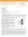
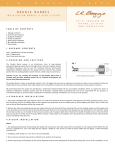
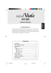
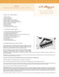
ANTHEM SL
INSTALLATION MANUAL
TM
1.PACKAGE CONTENTS
One Anthem-SL with TRU•MIC, Element pickup, endpin preamp, volume control and battery lead __ pre-assembeled
One battery bag
Six self-stick wire clips
Two adhesive pads for volume control
One extra adhesive set for Tru • Mic
2. OVERVIEW AND CAUTIONS
The Anthem SL Classical features our patent pending TRU•MIC microphone technology. The mic is designed to capture the majority of your guitar’s true voice in a
way that only a microphone is capable of - plus it is amazingly feedback resistant. Our Element under saddle pickup carries only the lowest frequencies for punch
and authority. The TRU•MIC and Element pickup are preset for optimum performance and the soundhole mounted controller has volume and mic gain trim controls.
This system must be installed by a professional dealer/installer. We do not provide installation advice or support for home or hobbyist installations. Installers: please
read the instructions carefully before proceeding. We will not be responsible for any damage to the guitar, pickup system or personal injury resulting from installation.
3. STRAPJACK INSTALLATION
Drilling the strapjack hole
For proper installation, this jack requires a clean 1/2” hole in the tail block of the
instrument. If the guitar lacks this hole, start by placing a piece of masking tape on
the outside of the instrument over the drilling area (to avoid chipping the finish),
drill a small pilot hole in the tail block and then follow with a step drill bit.
fig. 1
Installing the strapjack
Remove the strap ring, retaining nut and one washer from the smaller threaded
section of the jack. There should still be one star locking washer, one flat washer
and a nut remaining on the larger threaded section of the jack. Bring the jack down
through the soundhole into the body and insert it into the pre-drilled hole in the
tail block. Using the internal nut (be sure to include the flat and star washers), set
the proper depth that will allow the entire smaller threaded section to protrude
from the instrument (see figure 1). With the jack in place, lay the remaining washer
over the threads and attach the external retaining nut until it’s tight. Finish by
attaching the strap ring (it should cover the retaining nut and washer). Asserting
too much pressure may crack the finish.
Tail Block
4. ELEMENT PICKUP INSTALLATION
For optimum performance
The bridge slot must have a clean, flat surface free of debris and excess over-spray from lacquer, (sometimes left from guitar manufacturers). String balance problems
are often the result of an uneven interface between the bottom of the saddle and the saddle slot floor. Both surfaces must be completely flat to give you the best
chance at a successful installation.
The depth of the saddle slot is an important factor. A tip to help determine if your slot depth is adequate is the 50/50 rule which basically says: The amount of saddle
visible above the bridge surface (with pickup installed) should be equal to or less than the amount of saddle in the slot beneath the bridge surface. An installation in
which you have a tall saddle in a very shallow slot could be the cause of problems ranging from string to string imbalance, excess feedback, and poor tone quality.
Drilling the hole
Drill the hole at either end of the slot approximately 3/16” beyond the outer string. Use a bit no smaller than 3/32” but of course no larger than the width of the saddle
slot. Before you drill, inspect the inside of the guitar and note the position of the braces in relation to the saddle slot. Drill the hole at a slight angle being careful to
avoid all braces as the drill bit penetrates the top. Now using a small file or exacto blade, slightly chamfer and de-burr the edge of the hole where the pickup bends
to protect it from being kinked or pinched. Remove all loose debris from the slot (see figure 2).
Drill hole at slight angle
Avoid drilling through brace
3/16”
3/16”
Chamfer edge
Bridge
Guitar Top
fig. 2
Preparing the saddle
You will need to compensate for the thickness of the pickup in the overall height of the saddle by removing approximately .032” of saddle material. We recommend
you do this from the bottom of the saddle. This will allow you to make sure the bottom of the saddle is absolutely flat while maintaining intonation/compensation
on the topside.
Remove the majority of the material on a belt sander first. Finish it off by hand sanding against a perfectly flat surface with semi fine sandpaper; 180 to 220 grit paper
is good. Finally, check the flatness of the saddle by shining a light behind it while it rests on the flat surface.
Saddle fit
Another very important consideration is the fit of the saddle. The saddle should fit loosely enough that you could remove it from the slot using only your finger tips,
but not so loose that it will fall out if you were to turn the guitar over.
A saddle that fits too tight won’t be able to seat firmly on the pickup and thus will not function properly. The most common results of this are very poor string balance,
low output, low frequency microphonic response, boominess and bad tonality.
A loose fitting saddle will result in saddle tilt or lean while under
pressure. This will cause poor contact in a different way. When
the strings are at full tension, the saddle will pull forward and
distribute pressure solely on the front edge of the pickup. This
will result in poor tonality and possible string balance problems.
One way to compensate for a loose fitting saddle is to sand an
intentional angle on the bottom surface of the saddle so that it
will make even contact under full string tension (see figures 3a
& 3b). This is not an easy task to accomplish accurately, so we
recommend that only the most experienced installers attempt
this. The best option is to create a new saddle.
Ideal Saddle Fit.
fig. 3a
Loose saddle
Proper saddle-pickup contact
(saddle lean exaggerated)
fig. 3b
Installing the pickup
Once you have the saddle prepared, feed the pickup into the slot from inside of the guitar. Tip: insert a tooth pick, small Allen wrench or similar object through the
hole from outside the guitar to aid you in locating the hole inside the guitar. As you lay the pickup in the slot, make sure the black dot at the end of the pickup is facing
up. This will insure proper pickup phase orientation. Place the saddle in the slot over the pickup and temporarily secure it with a piece of tape. Secure the wire with a
wire clip as close to the exit hole as practical (see figures 4a & 4b). Failure to secure the pickup may produce excess boominess and feedback.
Special considerations
Saddle material: Undersaddle pickups respond differently to various saddle materials and sometimes the differences can be startling. Variations in the saddle
material effect everything from output to string balance and tone. It’s sometimes a good idea to experiment with a couple different types of saddles to get the best
results.
5. TRU•MIC INSTALLATION
The TRU•MIC is designed to adhere directly to the guitar’s soundboard or bridge plate using the included peel-and-stick VHB adhesive. For optimum results, place
the mic directly under the bridge or as close as feasible (see figures 4a & 4b for placement recommendations). Unlike most soundboard transducers or internal
microphones, the TRU•MIC’s position is not critical. As such, repositioning the TRU•MIC to find the optimal location should not be necessary.
Prior to attaching the TRU•MIC, be sure to clean the intended mounting surface to remove dust, oil or any other debris. Remove the backing from the adhesive pads
on the TRU•MIC and carefully place it in the desired location on the soundboard or bridge plate. Press firmly on the TRU•MIC while applying equal counter-pressure on
the guitar top from the outside of the guitar to prevent damaging the soundboard.
Now secure the wire with the provided self-stick wire clips. It is helpful to secure the leads from both the Element and TRU•MIC with the same wire clip at the point
where they come together beneath the bridge (figures 4a & 4b).
6. TRU•MIC REMOVAL
If, at some point, you wish to remove the Tru-Mic or want to experiment with placement, here is the recommended method of removal. The VHB adhesive is very
strong and increases its bond with age so it’s important to proceed with caution. To remove, get a firm grasp on the Tru-Mic from the sides and gradually twist back
and forth as you pull it away from the soundboard or bridge plate surface. Don’t try to pull too quickly or with too much force as you may inadvertently damage the
soundboard. Maintain firm and steady tension as you pull and twist and it will come free after a few moments. If there is any adhesive remaining on the mounting
surface, it should be easily removed by your thumb or fingertip.
fig. 4a
without bridgeplate
fig. 4b
with bridgeplate
6. BATTERY BAG PLACEMENT
Stick the double-sided adhesive to an easily accessible spot on the back, side or neck block. Insert the battery and battery snap into the bag. The battery can then be
changed by opening the flap on the bag and pulling out the battery.
7. MOUNTING THE CONTROL
Attach the adhesive pad to the volume control. Remove the protective backing
from the adhesive pad and mount the control in a convenient place on the rim of
the soundhole. Make sure the mounting area is thoroughly cleaned to insure good
adhesion.
Roll this wheel towards the neck to increase the volume or towards the bridge to
decrease the volume.
Secure all wires with the wire clips provided and re-string the guitar.
8. TESTING & ADJUSTMENTS
Plug into your acoustic amp or PA and confirm that the EQ controls are at their
default positions.
fig. 5
A. MIC LEVEL CONTROL ( Adjusts the level of the TRU•MIC relative to the level
of the Element)
IMPORTANT: Setting this control correctly is vital to the sound of the Anthem
system.
Play through a P.A. or acoustic amplifier while you are making adjustments. A
small flat-head jeweler’s screwdriver will be needed.
Your amplified tone should be well balanced and true to the acoustic sound
and feel of the guitar. If it lacks clarity and top-end, increase the mic’s level by
turning the control clockwise. Back it off slightly If you experience excessive
handling noise and/or brightness.
A
B. VOLUME CONTROL
483
N. FRONTAGE ROAD
•
NIPOMO, CA
• 93444 • (805) 929 - 3545 •
W W W. L R B A G G S. CO M
B