1
1-4
Safety Application Instructions General Information
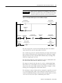
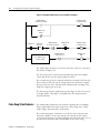
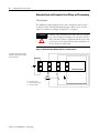
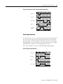
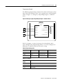
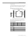
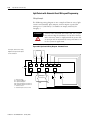
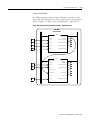
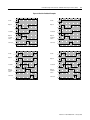
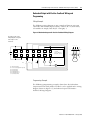
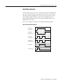
Figure 1.3 Example Ladder Logic to Latch and Reset an Output
Output Module
Connection Faulted
Output Faulted
*** Internal Tag ***
L
Output Point
Status
Fault Reset
Fault Reset
Oneshot
Output Module
Connection Faulted
Output Point
Status
ONS
Output Faulted
*** Internal Tag ***
U
Output Faulted
*** Internal Tag ***
Output Point
Data
User defined logic to
activate output
The ladder logic in Figure 1.3 has the same latch and reset concept as
that shown in Figure 1.2.
The first rung latches an internal indication that either the module
connection or the specific output point has failed.
The second rung resets the internal indication, but only if the fault has
been repaired, and only on the rising edge of the Fault Reset signal.
This prevents the safety function from automatically restarting if the
Fault Reset signal gets stuck on.
The third rung includes application-specific logic to drive the state of
an output point. This logic is conditioned by the output faulted
internal indicator.
False Rung State Behavior
The information provided in this manual regarding the GuardLogix
Safety application instructions depicts the “True Rung State” (Relay
Ladder Logic) behavior of the instructions.
The “False Rung State” behavior is exactly the same (internal state
machines continue to run and change states based on the inputs)
except that all outputs, including prompts and fault indicators, are set
to zero when the instructions are disabled or on a false rung.
Publication 1756-RM095A-EN-P - January 2005