1
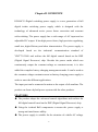
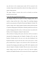
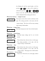
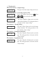
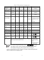
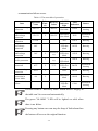
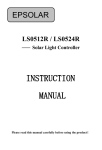
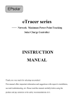
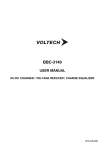
user manual Digital AC/DC Power Supply EG600CU 40~60V 0~10A USER MANUAL CONTENTS Chapter I ATTENTIONS ......................................................................... 1 Chapter II OVERVIEW ........................................................................... 3 Chapter III TECHNICAL SPECIFICATIONS................................................ 5 Chapter IV OPERATION MODE ............................................................. 7 Section I Power Mode Introduction ...................................................... 7 Section II Charging Mode Introduction.................................................. 8 Section III Multi-machine Operation ................................................... 10 Chapter V OPERATION INTERFACE ..................................................... 12 Section I Panel Shows.......................................................................... 12 Section II Human-Machine Interface ................................................... 13 Section III Display Operation ............................................................... 15 Chapter VI PROTECTION FUNCTION ................................................... 20 Chapter VII SIMPLE TROUBLESHOOTING GUIDE ................................. 23 Chapter VIII MAINTENANCE PROCEDURE ........................................... 25 Chapter IX OVERALL DIMENSIONS ..................................................... 26 All rights reserved. The contents in this document are subject to change without notice. Chapter I ATTENTIONS Thank you very much for selecting our product! This manual offers important information and suggestions with respect to installation, use and troubleshooting, etc. Please read this manual carefully before using the product and pay attention to the safety recommendations. This manual contains important safety, function, installation and operating instructions for the digital power supply. The following symbols are used throughout this manual to indicate potentially dangerous conditions or mark important safety instructions. Please take care of it when meeting these symbols. CAUTION: Indicates a critical procedure for safe and proper operation of the digital power supply. NOTE: Indicates a procedure or function that is important for the safe and correct operation for the digital power supply. Safety Information Read all of the instructions and cautions carefully before installation. Reversing the load polarity is very easy to damage the equipment or come into the unpredictable dangers. Do not disassemble the product in order to avoid personal injury. -1- There is non-security voltage inside of the power supply. Please call the professionals in our company if you need repair. Do not install, replace parts or perform any unauthorized modifications on the instrument. Turn off the power before moving the working power supply. In order to avoid the risk of loose connection, please ensure that all connections are tight. Do not put heavy things on the power supply to avoid failures. -2- Chapter II OVERVIEW EG600CU--Digital switching power supply is a new generation of full digital isolate switching power supply which is designed with the technology of advanced active power factor correction and resonant soft-switching. The power supply has a wide range of AC input and an adjustable DC output. It has high power factor, high precision regulating, small size, high efficiency and other characteristics. The power supply is developed based on the industrial communication standard of YD/T731-2008 and realizes the full digital control based on the DSP (Digital Signal Processor) chip. Besides the power mode which can continuously output the constant-voltage or constant-current, it is also added the complete battery charging management mode. It can be used as the constant-voltage constant-current or battery charging power supply in order to meet the different applications. The input port can be connected to mains or the output of oil-machine. The product can form a hybrid power system with the other products. FEATURES The product adopts the advanced control algorithms and realizes the full digital control based on the DSP (Digital Signal Processor) chip. Using the isolated Hall components to assure the power supply a strong anti-interference ability. The power supply is suitable for the situation of volatile AC voltage -3- whose range from 176 to 265V. Output voltage can be adjusted continuously from 40 to 60V. The minimum adjustable voltage is 0.1V. Output current can be adjusted continuously from 0 to 10.5A. The minimum adjustable current is 0.1A. The output charging current can be set as constant according to the actual battery‟s AH. Without reducing rated power at the ambient temperature of 55℃. The power supply has a complete three-stages charging mode for bulk charge, equalizing charge and float charge. Multiple products with the same type can be connected in parallel or series and „Hot-Swappable‟ application can be realized. HMI uses the LED to display rich content, the 2X6 matrix buttons to realize concise menu operation. It also has other functions such as buzzer, LED indication, alarm and so on. RS485 communication is realized via RJ45 isolated port and CAN communication is realized via the isolated port. Using a standard chassis with the 19 inches width and the 2U height. -4- Chapter III TECHNICAL SPECIFICATIONS Table 3-1 EG600CU technical parameters Technical Index Parameter AC input voltage range AC input frequency range Power factor Surge Load regulation Power grid regulation Voltage-stabilizing accuracy Efficiency Standby power Item Output voltage in power mode Equalize Voltage Float Voltage Output current (limitary-current) Equalize Duration Equalize Calendar Item Working humidity Working temperature Storage temperature Dielectric strength Test Condition Vin220V,Vout40V~60V/10A Vin220V,Vout60V/10A Vin220V,Vout48V,0-10A Vin187~242V,Vout48V/10A Vin187~242V,Vout48V Vin220V, Vout40V~60V/10A Vin220V Setting Range MIN 176 47.5 86 Operation Tips MIN Continuous-adjustable; 40 Accuracy is 0.1V Continuous-adjustable; 40 Accuracy is 0.1V Continuous-adjustable; 40 Accuracy is 0.1V Continuous-adjustable; Accuracy is 0.1A Continuous-adjustable; 30 Accuracy is one minute Continuous-adjustable; 10 Accuracy is one day Environment Pointer Condition MIN Non-condensing Output without derating at +55℃ -15 -40 Safety Index AC-GND AC1500V one Minute DC-GND AC500V one Minute AC-DC AC3000V one Minute Structure Parameters -5- TYP 220 50 0.96 MAX 265 52.5 0.97 8 0.5 0.1 0.6 90.4 10 Default MAX UNIT V Hz A % % % % W Unit 48 60 V 57.6 60 V 54.8 60 V 10.5 10.5 A 120 180 MIN 30 90 DAY TYP MAX 95 +55 +85 Unit % ℃ ℃ 15 0.1 1 mA mA mA Dimensions(H&W&L) Output terminal Ground terminal Net weight(reference) 110(4.3)X 483(19.0)X 518(20.4) mm(inches) M6 M5 7Kg Please set up the charging voltage and current according to the battery’s parameters! -6- Chapter IV OPERATION MODE The product has two modes, one is power mode and the other is charging mode. The power mode has the character of constant-voltage constant-current and can be used as a conventional DC power supply. The charging mode has a perfect battery charging mechanism. Users can select the appropriate mode according to the actual application. Section I Power Mode Introduction Power mode has two output functions, one is constant-voltage and the other is constant-current. The DC output voltage can be set from 40 to 60V. The DC output current can be set from 0 to 10.5A. The output current is defined by the output voltage and the load resistance in power mode. The product outputs constant voltage and the green LED is lighted on solid, as long as the output current is lower than the limit current setpoint. If the load current is greater than the current setpoint, the device will be converted to constant-current mode and the red LED will be lighted on solid. The output can be switched automatically between the mode of constant-voltage and constant-current according to comparing the current setpoint with load current. For example, the device in the constant-voltage mode will be converted to the constant-current mode automatically when the load current excesses the setpoint. In the same -7- way, the device in the constant-current mode will be converted to the constant-voltage mode automatically when the load voltage reaches at the output voltage setpoint. The output voltage or current value can be set directly on real-time interface in power mode. Section II Charging Mode Introduction The charging voltage has two points in battery charging mode, one is equalize voltage and the other is float voltage. The equalizing charging mode has two parameters of Equalize Duration and Equalize Calendar. The equalize voltage, float voltage, Equalize Duration (duration after the stable of equalize charging point) and Equalize Calendar (period between the two equalize charging mode) all can be set. At the same time it can realizes the limitary-current charging by setting the output current. After each time of turning on the power, the device will be converted to automatic float charging mode, the Equalize Calendar will be start (the Equalize Calendar starts for the next cycle only after finishing the last Equalize Duration except for the first time of turn on the power). At this point, whether there is output or not, the device will be converted to the automatic float charging mode and the green LED will be lighted on solid when the Equalize Calendar is finished. When the device detects that the output voltage excess the value that is lower 0.5V than the equalize setpoint, the Equalize Duration will be start and will not be stopped until -8- it has been finished then the product will be converted to automatic float charge mode automatically and the yellow LED will be lighted on solid. The Equalize Duration will be paused until the condition is satisfied again if the voltage point is less than the value that is lower 0.5V than the equalize setpoint in half-way. There are two buttons on the panel, one is forced equalize charge and the other is forced float charge. It will be converted to forced equalize charging mode and the green LED flashes when pressing the forced equalize charging button in float charging mode. The next cycle is automatic equalize charging mode when the Equalize Duration and Equalize Calendar are finished after enabling the forced equalize charging mode. The function is invalid when the power supply has been in equalize charging mode. It will be converted to forced float charging mode and the yellow LED flashes when pressing the forced float charging button in equalize charging mode. The function is invalid when the power supply has been in float charging mode. The device will keep in float charging mode after the forced float charging mode has been enabled. The Equalize Calendar timer which has been started will be cleared (it starts once again until the Equalize Duration finished) when pressing the forced equalize charging button. The Equalize Duration which has been started without finishing will be paused when pressing the forced float charging button. It will not be cleared until the Equalize Calendar has -9- been finished in order to prevent the device to working in equalize charging mode for a long time during convert the mode repeatedly between forced float charging mode and forced equalize charging mode. Section III Multi-machine Operation Parallel Running Multiple same type power supplies can be connected in parallel, but the output voltage must be set at the same value. Turn on the power supply one by one. The load voltage is the same with each power supply and the load current is the sum of each power supply. The wiring diagram is shown below. Digital power supply + - Digital power supply + Digital power supply - + Figure 4-1 Parallel connection - Cathode Anode + Series Running Multiple same type equipments can be connected in series, but the current value of output should be set consistently. Turn on the power supply one by one. The load current is the same with each power supply and the voltage is the sum of each power supply. The wiring diagram is shown below. Suggest: The output of each power supply should parallel a power resistance of 10K / 1W and a protection diode (pay attention to the -10- technical parameters of the diode). Digital power supply Digital power supply Digital power supply + + + - - Cathode Anode + Figure 4-2 Series connection -11- Chapter V OPERATION INTERFACE Section I Panel Shows 1 Front Panel: 2 Figure 5-1 Front panel Rear Panel: 3 5 6 4 8 Figure 5-2 Rear panel Illustrate: ① ON/OFF switch ② Human-machine interface ③ RS485 port ④ CAN bus port ⑤ DC output Negative terminal ⑥ DC output Positive terminal ⑦ DC output fuse ⑧ AC input socket with insurance (Note: CAN bus port is reserved) -12- 7 Section II Human-Machine Interface Figure 5-3 Human-machine interface Table5-1 Interface specification Items LED indications Code Action Function Constant-voltage output Constant-current output Automatic equalize charging mode Forced equalize charging mode Automatic float charging mode Forced float charging mode Power Mode Charging Mode CV Green On solid CC Red On solid EC Green On solid Green Blink Yellow On solid Yellow Blink Green Green Red and Green Off On solid FC MODE ALARM Soft-touch button Color MEC Forced equalize charging mode Forced float charging mode Menu switch MFC MENU -13- Remark Specific to see “Table 6-1 The state table of protection” Valid only in charging mode Valid only in charging mode Switch between the interface of real-time, SET Enter setting ESC OK ↑↓ Exit setting Confirm setting Change the setting value or the page of interface Move the cursor between the bits of the value or the page of interface Switch between the power mode and charging mode Turn on or off the output ←→ MODE OUT Alarm buzzer setting and failure. Exit setting without saving if no operation within 60 seconds. Display the last operation mode when turning on the power each time. Turn the output on or off on any page except setting state The alarm of faults ; Button operation tips; Buzzing when pressing any button each time Display the parameters, failure tips and so on “*” tube Interface description: The interface includes three parts, real-time, setting and failure. The page of failure does not exist when there is no failure. Each interface contains several pages to display the actual contents. Press ↑ or ↓button to flip page cyclically. Press ← or → button to jump to the first or last page of the interface. -14- The power mode or charging mode, real-time clock and day generating capacity will not be changed or cleared. They will maintain the current mode or parameters when restoring the factory settings. When restoring the factory settings, the device will be converted to the automatic float charging mode. The Equalize Duration and the Equalize Calendar are cleared. The last working mode and parameters will be selected when turning on the power supply. Section III Display Operation Initialization EG600CU The device type is displayed firstly when turning on the power. Power Mode MENU V.OUT 48.0 MENU ID. 02 MENU 1.IOVP The interface will be changed circularly between the interface of real-time, setting and failure when pressing MENU. Press↑ or ↓ button to flip the page cyclically. Press ← or→ button to jump to the first or last page. ▼Real-time Interface — Output Voltage The interface of “Real-time Output Voltage” will be V.OUT 48.0 displayed if the initialization is normal. During setting , the first digit flashes when pressing SET, -15- the flashing bit will be moved right or left by pressing → or ←, the value will be added or subtracted by pressing ↑ or ↓ . Press OK or ESC button to save the value or not. The current status will be maintained when setting up the device. ▼Real-time Interface — Output Current C.OUT 10.0 The output current value can be set directly in this page. The setting procedure is the same with the “output voltage”. The device will not stop running when setting in both modes. ▼Real-time — Output Power Real-time output power can‟t be set in both modes. P.OUT 600 ▼Real-time — Input Voltage V.IN 220 Real-time input voltage can‟t be set in both modes. ▼Real-time — Date DT.14.05.18 The real-time date value can be set in this page. The setting procedure is the same with the “output voltage” in both modes. ▼Real-time — Time TM.09.12.55 The real-time time value can be set in this page. The setting procedure is the same with the “output voltage”. This page exists in both modes. ▼Set Interface — Device Address ID. 02 The device‟s ID can be set in this page without -16- shutdown in both modes. The setting procedure is the same with the “output voltage”. ▼Set Interface —Series Rate SBR 1152 The SBR can be set in this page without shutdown in both modes. The setting procedure is the same with the “output voltage”. Press ↑ or ↓ button to change the value. ▼Set Interface —Restore Factory settings RSET YES Restore factory settings. The setting procedure is the same with the “output voltage”. Press ↑ or ↓ button to change the value. The device will be shut down when saving the setting value. Table 5-2 The parameters in power mode Item Code MIN Default MAX Unit Output voltage V.OUT 40.0 48.0 60.0 V Output current C.OUT 0.0 10.5 10.5 A Real-time output P.OUT W power Real-time input V.IN V voltage Real-time date DT Y.M.D Real-time time TM H.M.S Device address ID 0 2 180 Serial port baud SBR 9600 115200 115200 B rate Restore factory RSET NO YES settings Failure interface Fault codes in power mode:IOVP, ILVP, IOCP, OOVP, OLVP, OSCP, DOTP, BOVP, ONLP, CFAL -17- Remark Fixed Fixed Press ↑ or ↓ button to change the value. Press ↑ or ↓ button to change the value. The largest figure represents the latest failure. The letters represent the failure code. Charging mode ▼Real-time Interface --Output Voltage V.OUT 54.8 The page of real-time output voltage can‟t be set. ▼Real-time Interface --Generating Capacity of Day D.GE 5.15 Power value flashes when pressing SET. Press OK or ESC button to clear the value or not. ▼Set Interface --Equalization Voltage V.EC 57.6 The value of equalize voltage can be set in this page without shutdown. The setting procedure is the same with the “output voltage”. ▼Set Interface -- Floating Voltage V.FC 54.8 The value of float voltage can be set in this page without shutdown. The setting procedure is the same with the “output voltage”. ▼Set Interface --Equalization Hold Time T.EC 120 The value of Equalize Duration can be set in this page. The setting procedure is the same with the “output voltage”. ▼Set Interface --Equalization Cycle CT.EC 30 The value of Equalize Calendar can be set in this page. The setting procedure is the same with the “output voltage”. -18- Table 5-3 The parameters in charging mode Item Real-time charging voltage Output current Real-time output power Real-time input power Generating capacity of day Code MIN Default MAX V.OUT C.OUT 0.0 10.5 10.5 Unit Remark V Fixed A P.OUT W Fixed V.IN V Fixed Manual reset; Automatic reset(when KWH the real-time is zero hour); Power on Y.M.D H.M.S D.GE Real-time date DT Real-time time TM Equalize charging V.EC 40.0 57.6V 60.0 V voltage Float charging V.FC 40.0 54.8V 60.0 V voltage Equalize Duration T.EC 30 120 180 MIN Equalize Calendar CT.EC 10 30 90 DAY Device address ID 0 2 180 Serial port baud Press ↑ or ↓ button to SBR 9600 115200 115200 B rate change the value. Restore factory Press ↑ or ↓ button to RSET NO YES settings change the value. Failure interface The code of failure in charging mode: IOVP, ILVP,IOCP, The largest figure OOVP, OLVP, DOTP, BOVP, CFAL represents the latest failure. The letters represent the failure code The failures and pressing any button of MODE OUT will stop the output, but the current charging status will not be affected. The Equalize Duration will be paused when working in equalize charging mode and the Equalize Calendar without being affected when working in float charging mode. -19- Chapter VI PROTECTION FUNCTION Input Under-voltage and Over-voltage Protection To prevent long-term work in the case of low voltage or high voltage which will shorten the life or damage the equipment when the grid fluctuates heavily. The device will be shut off when the over-voltage or under-voltage occurs. It will be recovered automatically when the grid voltage is normal. Input Over-current Protection It will trigger input over-current protection when turning on the power or the input current is too large cased by abnormality. Output Short-circuit Protection It will trigger short-circuit protection when the output short-circuit occurs. Power supply has a once-time self-recovery function of output short-circuit. The device will be shut off after one second when the load wirings are connected together. The system will be recovered automatically after five seconds for the first time. If the load is still short-circuit, the system will be shut off and no longer recovered automatically. If the system does not detect the short circuit fault once again after the first time within one minute, the system will reset the self-recovery function of output short circuit and repeat the above process。 Output Under-voltage and Over-voltage Protection -20- The device has output over-voltage protection. It will be shut off automatically and the LED of the corresponding failure will be lighted when the output is over-voltage. It will trigger under-voltage protection when the output voltage is too low. The system will be shut off after two seconds. The remaining protections and self-recovery mechanism are consistent with the protection of output short-circuit. Bus Over-voltage Protection It will trigger bus over-voltage protection to prevent the equipment being damaged when the input DC bus voltage is too large caused by abnormality. No-load Protection in Power Mode It will trigger no-load protection to prevent the device working in no-load mode for a long time, save energy and extend the life when working in power mode. Over-temperature Protection The device has over-temperature protection and self-recovery functions. The system is designed with sufficient margin in normal operating conditions. If the temperature of heat sink exceeds 85℃, the device will be shut off automatically and recovered below 75℃. Communication Failure It will prompt users communication failure when there is a communication error between human-machine interface and internal control circuit. The device must be restarted immediately when the -21- communication failure occurs. Table 6-1 The state table of protection Item Input overvoltage protection Input undervoltage protection Input overcurrent protection Output overvoltage protection Output undervoltage protection Output short circuit protection Over temperature protection Bus overvoltage protection No-load protection in Power Mode Communication failure Operation Value Delay Time (S) Recovery Values 265±3V 2 250±3V 176±3V 2 190±3V 12.5A 94V ALARM Indicator Light Red LED fast blink LED Indication Buzzer IOVP Intermittent buzzing Red LED slow blink ILVP Intermittent buzzing Off IOCP Buzzing OOVP Buzzing OLVP Buzzing OSCP Buzzing DOTP Intermittent buzzing Green LED fast blink Green LED slow blink Orange LED blink Orange LED slow blink 2 Self-recov ery 1 Self-recov ery 85℃ 5 75℃ 475V 1 OFF BOVP Buzzing 0A 2 Red LED blink ONLP Buzzing Orange LED fast blink CFAL Intermittent buzzing 30V The null items of "Recovery Value" which need to reapply in the table can‟t be recovered automatically. The green "ALARM " LED will be lighted on solid when there is no failure. Pressing any button once can stop the beep of fault alarm then the button will recover the original function. -22- Chapter VII SIMPLE TROUBLESHOOTING GUIDE Item Failure Possible Reasons Simple Solution 1 HMI displays “IOVP”; Red LED fast blink; Intermittent buzzing; Output termination. The input voltage is too high; The input voltage has a great fluctuation. 2 Input undervoltage; HMI displays “ILVP”; Red LED The input voltage has slow blink; a great fluctuation. Intermittent buzzing; Output termination. 3 HMI displays “OLVP”; Green LED slow blink; Always buzzing; Output termination. Measuring the input voltage is too high or not; Checking the value of input voltage is accurate or not; If the input is mains, it will be recovered automatically after mains has been recovered. If the input is oil-machine, it needs to be turned off. Then checking the state of the oil-machine. Measuring the input voltage is too low or not; Checking the value of the input voltage is accurate or not; If the input is mains, it will be recovered automatically after mains has been recovered. If the input is oil-machine, it needs to be turned off. Then checking the state of the oil-machine. Please make sure that the current exceeds the limitation and then increase it when connecting with a resistive load and so on. Checking the battery voltage is normal or not (Only 48V system). Make sure that the battery Output undervoltage during work process; Load current exceed the current limitation set by the current set value. -23- 4 5 6 7 has been damaged or not and replace it in time when connecting with battery. The system has a recovery function and needs to be turned on again when exceeding the recovery time. HMI displays Output is short circuit Checking the output is when working; short circuit or not. “OSCP”, Red and Orange LED light on Output has short The system has a recovery solid; phenomenon. function and needs to be Always buzzing; turned on again when exceeding the recovery Output termination. time. HMI displays Over temperature The output will be “DOTP”; protection; recovered automatically as soon as the temperature Orange LED slow Temperature of heat becomes lower. blink; sink is too high. Intermittent buzzing; Output termination. In Power Mode: No load. In Power Mode: HMI displays The device will be shut off “ONLP”; Red automatically after 2s LED is lighted on when working in no load solid; status. Always buzzing; The device needs to be turned on again after Output termination. troubleshooting. HMI displays Communication The device needs to be failures. “CFAL”; Orange turned on again when LED fast blink; communication failure occurs. Intermittent buzzing -24- Chapter VIII MAINTENANCE PROCEDURE The company is responsible for free repair within 18 months starting from the date of shipment to the original end use,if the device is used under the environment and rules prescribed in the manual. Maintenance Procedure Before requesting warranty service, check the User Manual to be certain that there is a problem with the power supply. Return the defective product, the purchase invoice to us if problem cannot be solved. To obtain rapid service under this warranty, the returned products must include the product model, serial number and detailed reason for the failure, the operational parameters, type of batteries and system loads. This information is critical to a rapid disposition of your warranty claim. This warranty does not apply under the following conditions 1. Damage by accident, negligence, abuse or improper use. 2. Unauthorized product modification or attempted repair. 3. Damage during shipment. 4. Damage results from acts of nature such as lightning, weather extremes. 5. Irreclaimable mechanical damage. -25- Chapter IX OVERALL DIMENSIONS Unit:mm(inches) (4.33) (3.46) (17.32) (20.39) (17.79) (19.13) (19.0) Document Version: V4.0 -26- BEIJING EPSOLAR TECHNOLOGY CO., LTD. Tel:86-10-82894856 / 82894896 Fax:86-10-82894882 E-mail:[email protected] Website:http://www.epsolarpv.com Address:BLDG #18, CO.PARK, NO.8 HEYING ROAD, CHANGPING DISTRICT,BEIJING,CHINA.