1
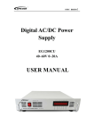
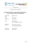
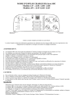
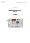
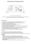
BBC-3140
USER MANUAL
DC-DC CHARGER / VOLTAGE REDUCER / CHARGE EQUALIZER
7673-3140-3520
Introduction
BBC-3140 is a Processor Controlled 3 Stage DC-DC Charger for charging 12V
lead acid batteries from a 24V DC source. It can also be used as a regulated
13.8V DC Voltage Reducer or a Charge Equalizer.
Available are 3 standard charging selections: Wet, AGM/Gel and CalciumCalcium.
There are also two user defined charging profiles in which user can set:
Absorption, Float Voltage and Absorption time via the optional Remote Display
Module.
Features
●
●
●
●
●
●
●
Micro-Processor Control.
Three in one unit. (24V-12V Battery Charger, Voltage Reducer and Charge
Equalizer)
Charging profile selection for Wet, AGM/GEL and Calcium-Calcium batteries.
Car ignition connection is available to enable operation only when the car is
operating.
Socket for Remote Battery Temperature Sensor.
Cooling fan with variable speed thermo control.
Following Protections :
1. Output Short Circuit (constant current).
2. Output Over Current.
3. Input Over Voltage and Under Voltage.
4. Output Over Voltage.
5. Over Temperature.
6. Output reverse polarity (thermal fuse).
7. Battery Over Temperature Protection when connected with remote
temperature sensor.
Front Panel Operation
LED 2 Charging Status: BLINKS = Charging ON = Full
SWITCH
SWITCH TO ↑ ON
LED1
1
AGM / GEL
OFF
2
WET
OFF
3
CALCIUM-CALCIUM
OFF
4
User Defined Charge A
ON
5
User Defined Charge B
ON
6
Output V = ½ Input V
LED1 OFF , LED2 OFF
All switches to OFF : Output = 13.8VDC
LED1 OFF , LED2 OFF
2 or more switches to ↑ ON : NO OUTPUT
LED1 BLINKS , LED2 OFF
A. LED operation status:
Green: Unit in normal operation and power on.
Red: Unit is not operating and is in protection mode or wrong dip switch
selection.
LED1. Battery type / DIP Switches status.
Indicates one of the three standard battery type is selected.
OFF:
Orange blinking: Error in setting of DIP switches. More than one switch set to
“ON”.
Orange constant: User defined charge profile selected. Must be used with
optional Remote Panel.
LED 2. Charging status:
Green blinking: Charging in progress.
Green constant: Charging stopped / Battery full.
D. Remote Temperature sensor socket for battery.
E. Output to battery or load.
F. Power ON / OFF switch.
G. Explanation of the DIP switches settings for Battery Type or charge
profile selection.
There are 6 DIP switches. Up position is the ON or Selected position.
Caution
Only one switch is allowed to be set to ON (up position) at any one time.
If more than one switch set to ON, output will shut down and the orange B LED will
blink until selection has been corrected.
DIP 1 UP:
DIP 2 UP:
DIP 3 UP:
DIP 4 UP:
AGM/GEL battery type. Absorption 14.1V, Float 13.2V.
Wet battery type. Absorption 14.4V, Float 13.5V.
Calcium-Calcium type. Absorption 15.5V, Float 13.8V.
User defined 1 in which Absorption, Float Voltages and Absorption
time are set via Remote Display Module.
DIP 5 UP: User defined 2 in which Absorption, Float Voltages and Absorption
time are set via Remote Display Module.
DIP 6 UP: Charge Equalizer with output voltage at half the input voltage.
All 6 DIP: All switches down or OFF : Unit becomes a DC Voltage Reducer with
regulated 13.8V output.
H. Remote Display connecting / connector is RJ12.
Installation and operation
Charger Mode
Mount the charger as close as possible to the battery bank to avoid voltage drop
due to long cables.
The cables must have proper sized lugs with heat-shrink insulation.
Correct fuses are to be installed at the positive terminals of both batteries.
The output cable should be large enough to handle 50 Amp current.
Check for correct polarity.
Terminal connectors must be tight.
1. Turn the power switch F to OFF position.
2. For ignition control, connect the red cable from back of the unit to the car’s
ignition switch. The unit will operate when ignition is switched ON and the
power switch F is in ON position.
3. For continuous operation connect the red wire from the back of the unit to the
positive 24V DC source such as a battery.
Protection
Input Low Voltage Disconnect (LVD) protection:
This is to protect the input DC source (usually starting battery). When the input
voltage is less than 21V for 5 minutes, LVD protection is triggered and output is
shut down. LED A turns to red. When the input voltage is back up above 24V for 5
minutes the unit will return to normal operation and LED A will turn to green.
Battery Over Temperature Protection (OTP):
When battery temperature is detected by remote temperature sensor to be over
60℃ the output will shut down and LED A will turn to red.
Input Over Voltage Protection (OVP):
When input voltage is higher than 32V output will shut down and LED A will turn to
red. When Input voltage drops down to less than 30V unit will return to normal
operation and LED A will return to green.
Output Over Voltage Protection (OVP):
When the output voltage is higher than 17.5V the output will shut down.
Unit needs to be switched OFF and then ON manually to restore normal
operation.
Output Over Current Protection (OCP):
When output current goes over 40 Amps the unit will operate in Constant Current
Mode condition.
Charging Profiles
FLOAT:
When the unit is switched ON and the current is less that 10Amps the charger will
stay in Float Mode at 13.2V to 13.8V. If the current drawn is larger than 10Amps
or the battery voltage is lower than 12.5V for 5 minutes the charger will enter into
Bulk Charge mode.
BULK:
In Bulk Charge Mode the charger will supply maximum (40Amps) until battery
voltage rises to selected Absorption voltage level. Unit will then enter into
Absorption Charge Mode.
ABSORPTION:
In Absorbtion Charge Mode the charging voltage is kept constant. The charger will
change from Absorption to Float when the charge current drops to 4Amps or after
3 hours in Absorption mode.
Voltage Reducer Mode:
When used as a Voltage Reducer switch all Dip switches to down (OFF) position.
The output will be a regulated DC voltage of 13.8V with a maximum 40Amp DC
current .
All protections are applicable in this mode as in the charger mode.
Note : LED1 and LED2 are both off in the Voltage Reducer Mode.
Charge Equalizer Mode:
When used as a Charge Equalizer switch Dip Switch 6 in up (ON) position.
Remote Display Module BBR-3100 (optional)
I.
Introduction
The Remote Display Module is an optional module which has two functions:
1. Displays real time key information of the BBC-3140.
2. Sets charging parameters of the two user defined charging profiles.
II. Connection
1. 10 Meters Phone Cable
2. In Line Coupler 6P6C
3. BBR-3100 Remote Display Module
III. Panel Buttons Operation
1.
2.
3.
4.
To switch ON LED backlight.
Scroll up display of the real time information of main unit BBC-3140.
Scroll down display of the real time information of main unit BBC-3140.
Enter input of charging parameters for the User Defined Charge Profiles.
IV. Indications
When Remote Display Module is connected to BBC-3140 it will display:
Initialization
Version of Software
Brand or Make
It will then scroll to show all the real time information according to the mode
selected in the main unit.
Following is displayed when in charger mode:
Battery type selected.
Charging voltage.
Charging current.
Temperature of the battery.
State of charging (bulk, absorption, float).
Type of fault if unit is in fault mode.
Following is displayed when in user defined charging mode:
Batt type shows: “U def” and so on.
When in Voltage Reducer Mode no battery type is shown and the display
shows “Power” or “Half” depending on the selection.
Decoding the indications of the display.
1. IUVP:
2. IOVP:
3. Over-temp:
4. Power:
5. Half:
Input Under Voltage Protection.
Input Over Voltage Protection.
Battery Over Temperature protection.
Unit is set at 13.8V Voltage Reducer Mode.
Output = Half the Input voltage. Charge Equalizer Mode.
V. Setting the User Defined Charging Parameters
The Absorption voltage (13.0V to 15.5V), float voltage (12.6 to 14.0V) and
maximum absorption time (1 to 6 hour) can be set in the User Defined Charging
Modes.
VI. Flow Chart of Value Setting Instruction
This example is how to set the values by user.
Specifications
Rated Output Power
40A at 13.8V
Efficiency
86%
Input Voltage Range
22 – 30VDC
Output Voltage Rage
See operation mode
DC-DC Battery Charger Mode
Float (GEL/AGM)
13.2V
Float (WET)
13.5V
Float (Calcium-Calcium)
13.8V
Absorption (GEL/AGM)
14.1V
Absorption (WET)
14.4V
Absorption (Calcium-Calcium)
15.5V
User Defined Float Voltage Range
12.6V ~ 14.0V
User Defined Absorption Voltage Range
13.0V ~ 15.5V
User Defined Absorption Time Range
1 ~ 6hours
DC Voltae Reducer Mode
Regulated Output Voltage
13.8V
Charge Equalizer: Output V = Half Input V
11 ~ 15V
Moving Output Voltage tolerance of Charge Equalizer
Half Input Voltage ±0.5V
Voltage Regulation:
Load
200mV
Line
80mV
Ripple & Noise
35mVrms
DC Input Current
No Load Input Current (Standby)
170mA
Full Load Input Current (at output 13.8V / 40A)
26.5A
Input Current Level when Output Short Circuit
2.5A
Protections
Input Low Voltage Disconnect (Auto reset)
21V
Input Over Voltage (Auto shut down)
32V
Output Over Voltage (Auto shut down)
17.5V
Output Over Current / Short Circuit (Auto reset)
41A
Battery Over Temp. (with remote temp. sensor)(Auto shut down)
60°C
Unit Over Temperature Protection
Yes
Reverse Polarity (Output)
30A x 2 Fuses
Approval
CE EMC EN55014
Dimensions (L x W x H) mm
243 x 156 x 61