1
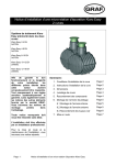
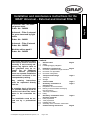
Installation and maintenance instructions for the
GRAF Universal – External and internal Filter 3
English
Universal Filter 3 for external green areas
Order- No.: 340020
Universal – Filter 3 external
for areas traversed by light
traffic
Order- No.: 340021
Universal – Filter 3 internal
Order- No.: 340022
Modular add-on pack 2
Order- No.: 342002
The points described in these
instructions must be followed
correctly. If not correctly observed, any right to claim on
the guarantee may be refused. For all additional
GRAF articles purchased
there are separate installation
instructions enclosed in the
transportation packing.
Any missing instructions
must be requested directly
from us.
A complete check of the tank
for possible damage must be
carried out before the installation in the excavation begins.
The installation must be carried out by a professional
firm.
Contents
1.
1.1
1.2
2.
2.1
2.2
2.3
3.
3.1
3.2
4.
5.
5.1
5.2
5.3
5.4
6.
General notes
Safety
Labelling/Tagging obligation
Page 2
Installation requirements
Page 2
Universal 3 pedestrian weight resistant
Universal 3 for light traffic
Universal 3 integrated
Transport and storage
Transport
Storage
Page 3
Technical data
Page 3
Assembly / Installation of
external Filter
Preparation of the excavation
Placing in the excavation and laying
the connections
Telescope installation
Filling
Page 4
6.1
6.2
6.3
6.4
Assembly / Installation of the
Page 5
Universal 3 Internal
Filter preparation
Tank preparation
Installing the Filter
Assembly of the extraction mechanism
7.
Commissioning and Service
US Adaptation Copyright RainHarvest Systems, LLC
Page 1 of 6
Page 6
1. General notes
1.1
Safety
When working on the installation, the appropriate accident prevention regulations (in Germany BGV C22) must be followed. For safety reasons, especially when entering the tank, it
is important that a second person is present.
Furthermore, when carrying out assembly and installation work, inspection, maintenance and
repairs, all work regulations and norms must be followed. You will find the advice in the appropriate sections of these instructions.
The installation of the system and/or single equipment parts must be carried out by a professional worker.
The complete system must always be out of operation and guarded against unauthorized
use when carrying out work on the plant or parts of the system.
The tank cover must always remain closed except when working in the tank, otherwise there
exists a very high danger of accidents. The seating and condition of the cover must be
checked on a regular basis.
The GRAF Company offers an extensive range of accessories that are all compatible with
one another and may be used to construct a complete system. The use of other manufacturers’ accessories can impair the function of the system and liability for any resulting damages
will no longer be covered under the guarantee.
1.2
Labelling/Tagging obligation
All pipe work and outlets of the water systems are to be labelled with the words “Not drinking water” either in words or graphically (German norm DIN 1988 Part 2, paragraph 3.3.2.)
so that after years of use, an accidental connection to the drinking water system is prevented. Even when correctly labelled it may possibly be mistaken, for example by children.
For this reason, all the outlets of the systems process water must be fitted with child safe
valves.
2. Installation requirements
2.1
-
2.2
-
-
2.3
-
Universal – Filter 3 pedestrian weight resistant
The Filter with the green telescopic attachment and cover may only be installed in green
areas that are not traversed by traffic.
The amount of short-term load of the polyethylene cover is max. 150 kg, the long-term
area load max. 50 kg
The maximum installation depth to the filter bottom is 1050 mm.
Roof areas provided with a pipe connection of DN 100 = 350 m² and for DN 150 = 500
m².
Universal – Filter 3 external for light traffic
Through the use of the telescopic attachment (anthracite) and the cast iron cover Class B
according to DIN EN 124 the filter may be installed in areas traversed by light traffic. Under no circumstances are the tanks to be installed in areas traversed by heavy goods vehicles or machinery (see point 5.3.2)
The earth covering above the inlet supply pipe must be at least 450 mm; the maximum
installation depth to the filter bottom is 1050 mm.
Roof areas provided with a pipe connection of DN 100 = 350 m² and for DN 150 = 500
m².
Universal – Filter 3 integrated
The Filter is suitable for installation in a pilot shaft or in a cistern.
The difference in height between the supply pipe and outlet is 250 mm
The Filter may not be installed directly in the earth.
The filter is suitable for roof areas up to 300 m².
US Adaptation Copyright RainHarvest Systems, LLC
Page 2 of 6
3.1
Transport
During the transport the filter must be well secured against slipping or falling. If the Filter is
to be secured for transportation with webbing straps, it is to be ensured that the filter remains
undamaged.
Stress and excess loading caused by impact are to be avoided. Under no circumstances is
the filter to be rolled or slid over the ground surface.
3.2
Storage
Any necessary temporary storage of the filter must be on an appropriate level surface without
sharp objects. During the storage it is important to avoid damage caused by the surrounding
environment or foreign objects.
4. Technical data
US Adaptation Copyright RainHarvest Systems, LLC
Page 3 of 6
English
3. Transport and storage
5. Assembly and installation of external Filter
5.1
Preparation of the excavation
So that sufficient working room is available and the filter can be evenly embedded, the surface area of the excavation should exceed the filter dimensions on all sides by approximately
50 mm. The excavation slope is according to DIN 4124. The installations excavation must
be level and smooth. The depth of the excavation must be measured so that the final installation depth of the filter bottom is a maximum 1050 mm. As an under surface for setting down,
a layer of smooth sand with a grain size of 8/16 according to DIN 4226 – 1 and a layer depth
of approximately 10 mm should be used.
Important: The setting down surface for the filter must be absolutely level to ensure an optional performance.
5.2
Placing in the excavation and laying the connections
The filter is installed in the prepared excavation and is then connected to the relevant pipes
etc. Attention, it is important to note that all the pipes to be installed have a must have a gradient of at least 1% in the flow direction without sagging or bending downward. An emergency run-off must also be connected so that a congestion or back surge may be avoided.
Important: DIN 1986 must be followed, therefore the diameter of the supply pipe = the diameter of the run-off pipe.
5.3
Telescope installation
5.3.1 Telescope pedestrian resistant
The telescope is pressed into the filter housing
from above. For excavation depths < 930 mm
the telescopic attachment and in some
circumstances, the filter housing must be
shortened.It is important to pay attention that
the inlet pipe is not obstructed in any way by
the telescope when installed. Before pushing
in the telescope the profiled sealing ring is
placed in the housings recess. The telescope
and the sealing ring must be thoroughly coated
with the lubricating soap included in the delivery (use no lubrication that is mineral oil based).
Attention: If the lubricating soap becomes dry and the telescope becomes difficult to move
then there is the danger that the sealing ring will be forced out of its recess. Before filling, the
sealing ring must be checked once again that it is seated correctly in position. The telescope
must be sufficiently embedded and supported that no forces are transferred to the housing.
5.3.2 Telescope suitable for light traffic
The telescope is installed as in Point 5.3.1. To ensure the function in areas traversed by light
traffic, the telescope must be embedded around the collar with lean mixed concrete.
The concrete encasement must be uninterrupted, 20 cm wide and approximately 30 cm
deep. Attention: It is important to use the cast steel cover. Transport vehicle weight of heavy
goods vehicles and machinery is not permitted. The telescope must be sufficiently embedded
and supported that no forces are transferred to the housing.
5.4
Filling
Important: Before and during the filling, the horizontal position of the filter must be checked.
The lengthwise embedding of the filter is with smooth sand with a grain size of 8/16 according to DIN 4226 – 1 with a width of approximately 30 cm
Each layer is to be of no more than 30 cm and must be tamped down lightly with a compacting machine or hand held tamper. Care must be taken during the embedding to ensure the
filter is not damaged. To ensure that no forces are applied to the filter housing, the telescope
must be well embedded and compacted. (For areas traversed by light traffic see section
5.3.2) Finally, the cover is set in place and secured so that it is child proof (Section 1.1 must
be followed). The screws holding down the cover are to be made so tight that they can
not be removed and the cover opened by a child!
US Adaptation Copyright RainHarvest Systems, LLC
Page 4 of 6
6. Assembly / Installation of the Universal 3 Internal
Length of the HT/canalisation pipe – connections (completed on site) from
the filter to the inlet connection and including the coupling:
Diamant:
2.200 lt.:
3.350 lt.:
4.800 lt.:
6.500 lt.:
7.800 lt.:
9.200 lt.:
Carat:
800 mm
1050 mm
1350 mm
1650 mm
1900 mm
2200 mm
2.700 lt:
3.750 lt:
4.800 lt:
6.500 lt:
7.500 lt:
9.600 lt:
13.000 lt:
1220 mm
1350 mm
1510 mm
1700 mm
1350 mm
1510 mm
1700 mm
6.2
Tank preparation
The siphon is installed in the lowest seal (3)
of the tank dome. The inlet pipe (150 mm
long) is mounted on the side opening (1); the
pipe is inserted from the outside. The
emergency overflow (2) (pipe length 250
mm) is installed above the siphon (3) and is
installed by pushing through from the inside.
Important: The sealing ring from the HT –
pipe coupling of the emergency overflow (2)
must be removed.
6.3
Installing the Filter
The fixing collar is pushed over the inlet pipe that is
mounted on the tanks’ dome. Finally the prepared
filter assembly is placed into the tank dome from
above then connected with the emergency overflow
and inlet pipe using the fixing collar. In this case it is a
butt joint that requires no collar.
6.4
Assembly of the extraction mechanism
Remove the seal from the filter basket and push the
metal angle of the lift out mechanism over the rim as
shown in the picture.
Finally place the seal over the rim and pull back the
metal angle.
US Adaptation Copyright RainHarvest Systems, LLC
Page 5 of 6
English
6.1
Filter preparation
Before the installation in the tank, the filter must be prepared as shown in the adjacent depiction.
7. Commissioning and Service
Before commissioning and at every inspection, the lifting out mechanism must be positioned
at 90° to the inlet so that no large objects such a s leaves and twigs can catch on the handle.
The straining filter is removed for cleaning and the basket must be thoroughly cleaned with
water until all the pores are open. It is advised to clean every 4 to 5 weeks (more often in
Autumn due to more leaves and twigs) or according to requirements.
The filter strainer basket must be lightly pressed into place taking care that the seal sits precisely after every cleaning.
At the occasion of each inspection, the overflow siphon must be checked and flushed in necessary.
Otto GRAF GmbH, Carl-Zeiss-Straße 2-6, D- 79331 Teningen – Tel.: 0049/(0)7641/589-0, Fax: 0049/(0)7641/589-50
www.graf.info, [email protected], Stand: 01/08
GRAF Distribution SARL 45, route d'Ernolsheim, F- 67120 Dachstein-Gare – Tel.: 0033/388497310, Fax: 0033/388493280
www.graf.info, [email protected], Version: 01/08
GRAF IBERICA Tecnología del Plástico S.L. – Sant Miquel 37 – ES-17003 Girona – Tel.: 0034/972913767 – Fax: 0034/972913766
www.graf.info, [email protected], Versión: 01/08
US Adaptation Copyright RainHarvest Systems, LLC
Page 6 of 6