1
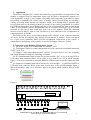
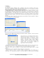
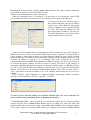
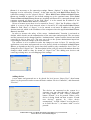
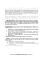
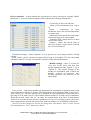
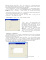
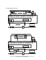
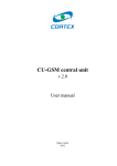
INTIEL
THE ELECTRONICS ON YOUR SIDE
Building Management System (BMS)
User’s Manual
tel.:00359 596 333 66 ||| fax:00359 596 325 80 ||| [email protected] ||| www.intiel.com
9 Peter Beron Str, Pomorie 8200, Bulgaria
1
1. Application
The devise is designed for a control and monitoring of great number of temperatures. Each
module is equipped with 10 temperature inputs type Pt-1000 or independent contacts of a
room thermostat, as well 10 relay outputs concerning each temperature point and one output
for sending a command to the central source of energy. The device has ability for selecting a
cooling or heating mode depends on customers’ needs, as in heating mode it provides antifreezing protection of the heating system. By means of the weekly programmer it could be
kept different temperature levels during each day of the week within four time periods during
a day. To each module could be added another one, as it could be fixed from 1 up to 255 subnetworks as each one of them could have from 1 up to 255 modules. When the connected
devices are more than 32, then to each 32nd device is to be added an active recapitulation or
connection-block for RS485.
The control of the device is provided by means of PC software, as the connection between
the device and the PC could be done through a local network or internet. There is an option
for a level access limitation, which prevents incompetent intervention in the system. A
comprehensive description of the software is exposed in chapter “Software” bellow.
2. Connection of the Building Management System
2.1 The power supply is to be connected to terminals ~230V.
2.2 Temperature sensors or contact thermostats are to be connected to terminals mentioned
with T1 up to T10.
2.3 Outputs – relay independent contacts 3A/250V, as outputs from 1 to 10 are switching,
and output Heating/Cooling only switching on contact.
2.4 PC communication input or input for previous module “IN”, as it is to be used FTP or
UTP cables with connectors RJ45, as the cable is to be done as for “PC to HUB”/straight/
figure 1. It is to be connected to converter RS485 to USB in order to provide connection with
PC.
2.5 Output for communication with a next device “Next module” – it could be used FTP or
UTP cable with connectors RJ45, as the cable is to be done as PC to HUB /straight/ figure 1.
When the module is only one or last one a tap is to be placed which could be find out in the
device set.
Figure 2
.
~230V
Output10
Output 9 Output 8
Output 7 Output 6 Output 5 Output 4 Output 3 Output 2 Output 1 Heat./Cool.
CON5
Next
Module
IN
PC
Т10
Т9
To Next
Module
Т8
IN
Т7
Т6
Т5
Т4
Т3
Т2
Т1
RS485
to
USB
tel.:00359 596 333 66 ||| fax:00359 596 325 80 ||| [email protected] ||| www.intiel.com
9 Peter Beron Str, Pomorie 8200, Bulgaria
2
3. Software
3.1 Installation
The software requires Windows XP or Windows Vista and 10 MB free disk space.
Applications “Intiel Tracer Client” and “Intiel Tracer Server” are to be installed, as well the
drivers for RS485 to USB converter during its connection.
3.2 Intiel Tracer Server – manage all clients connected locally or remotely. Initially or with a
port changing the following announcement is being shown: “It could not be fix a connection
with the hardware”. The button OK is to be pressed in order to go on. The server can be
maintained only by user with administrator level. In “User Login” window is to be entered
Name and Password “admin”, which is the official user name and password for initial system
entering.
After pressing “Select” button the system passes to next window “Device controller”. It has to
be selected menu File and then Options
New users can be added or the existing ones edited in window “Options”. A new user can be
added by means of “New” button.
Unspecified text is to be added in fields “Name”,
Password” and “Names”. In field “Level” is to be
selected “Super operator” or “Operator”. “Super
operator” level has access to all settings in
software application Intiel Tracer Client.
“Operator” level is able only to monitor the
current values and parameters without an
opportunity to make any changes.
Changing the existing User date could be provided by double click above the operator name.
Then a new window “User” is being opened where the desired changes can be made.
Any User can be erased as initially it is being selected and the button “delete” is being
pressed.
The software is to be restarted in order the changes to come in force.
Window “Options”, “Device”- provides setting of connection type. The default one is
“Serial port” for connection by means of converter RS485 to USB between the Building
tel.:00359 596 333 66 ||| fax:00359 596 325 80 ||| [email protected] ||| www.intiel.com
9 Peter Beron Str, Pomorie 8200, Bulgaria
3
Management System and the software Intiel Tracer Server. The other possible connection
type is UDP by means of converter RS485 to LAN.
Call the system administrator in case of problems!
When the connection type is “Serial port” it is necessary to be selected the virtual COM
port to which the device is connected. The rest settings are to remain as default ones.
A tick is to be placed to UDP in order to
have UPD connection, also the IP address
of the device with which the information
will be exchanged is to be entered /RS485
to LAN/. The converter RS485 to LAN
has unspecified IP address 192.168.0.16.
For input /Destination/ port is fixed 1024,
and for output /Source/ one 1025.
In case of any IP conflicts there is opportunity to choose another free port. The settings of
RS485 converter to LAN are to be done in UDP field, as button “Options” is to be pressed, as
a new window is being shown where are being indicated current IP, ports, speed, network
mask and Gateway IP. All the previous mentioned settings could be changed by the user. If an
incorrect IP address is entered or it is forgotten, when there could not be provided
communication between Intiel Tracer Server and RS485 converter to LAN it is necessary to
be restored the factory settings. In order to restore to factory IP refer to “LAN settings” in
description “Building Management System, a reference control module” or “RS485 converter
to LAN”. Once after the factory IP address is restored, then it is necessary the following IP
address 192.168.0.016 to be entered in Intiel Tracer Server, UDP, Host. In field “Server”,
“Port”, port 8000 is entered as default, as it is to be changed with another free one in case of
conflict.
There could be chosen Bulgarian or English language concerning software operation
interface. It could be done in window “Options”, “General”.
To come in force all made changes the software and the device are to be restarted. The
device restart can be provided by means of stopping and starting.
3.3 Intiel Tracer Client – this is a software for connection with the devices, which operation
requires first the start of Intiel Tracer Server and to be added user with user name and
password with the relevant access rights. After Intiel Tracer Client is being started window
“User login” appears, as during initial starting or changing the location of Intiel Tracer
tel.:00359 596 333 66 ||| fax:00359 596 325 80 ||| [email protected] ||| www.intiel.com
9 Peter Beron Str, Pomorie 8200, Bulgaria
4
Server it is necessary to fix connection settings. Button “Options” is being selecting. The
language is to be selected by “General”, in the same way like with Intiel Tracer Server. For
connection settings is to be selected “Server”. When Intiel Tracer Client and Intiel Tracer
Server are installed at same PC the default settings are to be remained same. When Intiel
Tracer Client and Intiel Tracer Server are installed at different PCs connected through local
computer network of “Server” in the field “Host” is to be entered the IP address of the
computer where Intiel Tracer Server is installed.
In case of remote access there is to be entered in “Proxy”, “Host” the IP address of the PC,
which is a server of the local network, where is located a PC with installed Intiel Tracer
Client. In field “Host” of “Server” is to be entered a real static IP address of the global
internet network, which is the IP address of the computer where the application Intiel Tracer
Server is installed.
In order to increase the safety of the access “Authentication” function is activated as
default, which checks out the authentication of the user name and password. The user name
and the password can be changed and the “Authentication” option could be deactivated with
removing its tick in front of it. The user can refer to the system administrator/supervisor
concerning the network settings of the local network.
The software is to be restarted in order the changes to come in force. To enter the user
application a user name and password are to be placed, which are indicated in Intiel Tracer
Server, as depends on the level access those data could be only watched for level “User” or
changed for level “Super User”. The description bellow will give more information about the
changes which could be done by means of “Super User” like adding new devices and
removing existing ones, as well changing of the settings.
Adding devices
A user name and password are to be placed for level access “Super User”, then button
select is to be pressed in order to enter the basic window “Device Controller”, and afterwards
“Devices”
The devices are connected to the system in a
sequence way one after the other, as after each
one being added in field “Device searching”
button “Search” is to be pressed. When a new
device is being found out then a notice “Found
new devices” appears. In ““New device
enumeration”” in field “Subnet” is to be placed 1,
as in field “Device” 1, as button “Add” is to be
pressed.
tel.:00359 596 333 66 ||| fax:00359 596 325 80 ||| [email protected] ||| www.intiel.com
9 Peter Beron Str, Pomorie 8200, Bulgaria
5
The next device is being connected and “Search” button is to be pressed. After appearing of
the notice “Found out new device” in “New device enumeration” in field “Subnet” is to be
placed 1, as in field “Device” respectively 2 and the button “Add” is to be pressed. After each
pressing of “Add” button at the upper part of the window from left to the right appears a list
of “Multi-thermostat1”, “Multi-thermostat2”, etc. The same is being repeated until all devices
which are going to be monitored are being entered. The number of the subnets can be from 1
up to 255. When the devices are more than 32, then to every 32nd device are to be added an
active recapitulation or RS485 connection-block.
When the option “Auto generated” number is activated you have to be sure that the list from
the upper part “Multi-thermostat 1”, “Multi-thermostat 2”, etc. is complete and there are no
missed devices, because there could be dangerous of double named devices, and the software
will not be able to refer to the right one.
Change device number – from this filed it could be changed all numbers of subnets and
devices. First in filed “From number” the subnet and device numbers are to be entered which
suppose to be changed, as in field “To number” are to be placed the new numbers of subnet
and device. In case any device is being changed to subnet 0 and device 0, then it will be
deleted automatically from the list.
Automatic addition – from this field it could be automatically added in the list the existing
with real number devices connected to the system. There is opportunity for selection among
the following options:
• “In all subnets” – it scans all subnets from 1 up to 255 about devices. The procedure
takes time, as it could be interrupted by means of pressing “Stop” button as only the
devices which are being found will be added only.
• “In select subnet” - it scans the relevant subnet for devices from 1 up to 255 The
procedure can be interrupted by means of pressing “Stop” button as only the devices
which are being found will be added only.
• “Select device” – it adds only the selected device, assigned with the number of the
subnet and devices.
After selecting the desired option button “Search and add” is to be selected”
Clear list – from this field can be deleted not currently used devices in case to avoid the
window overburden with a large list of devices. There is opportunity for selection among the
following options:
• “In all subnets” – it deletes all existing list.
• “In select subnet” – it deletes the list with devices from the selected subnet.
• “Select device” – it deletes a particular device from the list as, assigned with number
of subnet and device.
After selecting the desired option button “Remove”
tel.:00359 596 333 66 ||| fax:00359 596 325 80 ||| [email protected] ||| www.intiel.com
9 Peter Beron Str, Pomorie 8200, Bulgaria
6
Device controller – in that window the relevant device can be selected for example “Multithermostat 1”, as a new window appears which contents the following information:
Current day of the week and time.
Name of each thermostat from 1 up to
10.
Inputs – temperature or room
thermostat, shows the current temperature
or contact state.
Indication ErrHi means the temperature
sensor is missing or it is interrupted.
Indication ErrLo means there is a short
circuit in the sensor.
Outputs – shows the current state of
each one of them. Green means switched
on, as red switched off.
Thermostat settings – button “Options” is to be pressed, as a new setting window is being
opened.
Field “Name” can be consisted of unspecified text up to 48 symbols. The tick concerning
“Module enabled” is to stop or permit the operation of the relevant thermostat.
Module settings – there is a timer for
every day of the week with four time
periods mentioned with “Option 1” up to
“Option 4”. The general settings of the
module are mentioned with “General for
module”, consists of hysteresis, antifreezing functions, and selection of the
input signal.
Time periods – each time period has an opportunity for assignation of operation time period
and a temperature which is to be kept. The temperature can be assigned within 10 up to 80 C,
with a step of 10C. The time periods can be assigned in hours and minutes, as the hours are in
the range of 0-24 with a step of 1 hour and the minutes within 10-50 with a step of 10minutes.
When the periods “from” and “to” are same for example hours from 24 to 24 and minutes
from 0 to 0 it means the time period is prohibited. In case of recovering of hour zones /have
same operation time periods/ the time period with less number is to be fulfilled with priority.
After the relevant changes for the day are being done, then button “Save”is to be pressed
for confirmation or “Exit” button for a denial.
tel.:00359 596 333 66 ||| fax:00359 596 325 80 ||| [email protected] ||| www.intiel.com
9 Peter Beron Str, Pomorie 8200, Bulgaria
7
Hysteresis selection – dt is within 2 – 10 °С, with a step of 1 °С. It shows the temperature
with which it should be decreased after reaching the assignation during heating mode or
increased during cooling mode in order to start the output again.
“Anti-freezing function” – it is active only in heating mode, as it can be assigned within 010°С with a step of 1°С. In case it is enabled the desired temperature will be kept despite of
the fact the module is not enabled. It can be prohibited with removing the tick in front
“Enable”
Selection the type of the input signal – there is opportunity for selection among temperature
sensor Pt-1000 or independent contact of a room thermostat.
After the relevant changes are being done, then button “Save” is to be pressed for
confirmation or “Exit” button for a denial.
General options – consists of timer settings and mode selection.
Timer – Device 1 – fix the current day of the
week, hour and minute of the module. In case a
tick is placed “Set all active devices”, then the
date and time will be fixed concerning all active
devices stated in the list in the same time.
Mode- Device 1- selection of operation mode
with placing a tick for “Heating” or “Cooling”
mode.
After the relevant changes are being done, then
button “Save” is to be pressed for confirmation
or “Exit” button for a denial.
Calibration – ATTENTION !
The calibration option is to be used only by authorized persons. The devices are calibrated
during the production, and second calibration is to be done in case of certain problematic in
measurement precision of the devices.
In case of calibration it is necessary jumper CON5/figure 2, pg.3/ to be removed. A resistor
of 1000Ω for temperature of 0 °С is to be connected to the output which is to be calibrated,
as the instructions mentioned at the display are to be followed. The test concerning 100 °С is
to be done with a resistor of 1385 Ω, as the instructions are to be followed again.
The tolerance of the resistors should not exceed 1%.
tel.:00359 596 333 66 ||| fax:00359 596 325 80 ||| [email protected] ||| www.intiel.com
9 Peter Beron Str, Pomorie 8200, Bulgaria
8
By means of placing a tick “Calibrate all inputs” it could be calibrated in the same time and
the ten module inputs. For that purpose after the notice “Please place a standard for 0 °С” to
each inputs are to be connected resistors of 1000Ω for 0 °С. Respectively after the notice
“Please place a standard for 100 °С” to each inputs are to be connected resistors of 1385Ω for
100 °С.
The tolerance of the resistors should not exceed 1%.
In case of any doubt about the incorrect calibration procedure button “Stop” is to be pressed
before termination of Stage 4 at the display.
After the procedure completion jumper CON5 among pin 1 and 2 is to be placed. /figure 2,
pg. 3/.
5. Technical data
Power supply
Nominal output
Nominal current trough the outputs
Nominal current trough the inputs
Temperature sensors
Humidity
Protection
~230V
10W
250V/3А
0,83 mA
Pt1000
0 - 80%
IP 20
6. Content of the set
Building Management System
Converter RS485 to USB
CD with software
Sensors Pt1000
Tap for RJ45
Converter RS485 to LAN
Desk control module
1 piece
1 piece
1 piece
10 piece
1 piece
optional
optional
tel.:00359 596 333 66 ||| fax:00359 596 325 80 ||| [email protected] ||| www.intiel.com
9 Peter Beron Str, Pomorie 8200, Bulgaria
9
7. Example application schemes
Room 10
Room 1
Boiler
start
N L
~230V
Output10
Output 9 Output 8
Next
Module
Output 7 Изход6
Output 5 Output4
Output 3 Output 2 Output 1 Heat./Cool
IN
PC
Т10 – room 10
To Next
Module
Т1 – room 1
RS485
to
USB
IN
Distributor line
Central
System
heat./cool.
Room 1
Room 10
N L
Start
~230V
Output10
Output 9 Output 8
Next
Module
Изход7
Изход6
Output 5 Output 4 Output 3 Output 2 Output 1 Heat./Cool.
IN
Room
thermostat
Т10 – room 10
To Next
Module
PC
Room 5
Т1 – room 1
RS485
to
USB
IN
tel.:00359 596 333 66 ||| fax:00359 596 325 80 ||| [email protected] ||| www.intiel.com
9 Peter Beron Str, Pomorie 8200, Bulgaria
10
2. Warranty
The warranty period is 24 months following the purchase date of the unit or its
installation by a qualified staff, but not exceeding 28 months after the production date. The
warranty is extended to the malfunctions that occur during the warranty period and are result
of the production reasons or defective used parts.
The warranty does not relate to malfunctions corresponding to not-qualified
installation, activities directed to the product body interference, not regular storage or
transport.
The repairs during the warranty period can be done after correct filling of the
manufacturer warranty card
Warranty Card
Manufacturer: INTIEL
Building Management System (BMS)
Product type
Production number
Production date
Dealer’s confirmation
Purchase date
Invoice number
Dealer’s name, address and
stamp
Seller’s name and signature
Installation date
Date
Company (address, stamp)
Installer’s name and signature
tel.:00359 596 333 66 ||| fax:00359 596 325 80 ||| [email protected] ||| www.intiel.com
9 Peter Beron Str, Pomorie 8200, Bulgaria
11