1
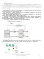
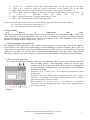
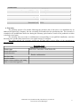
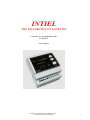
INTIEL
THE ELECTRONICS ON YOUR SIDE
Controller for accumulation tanks
INT0129-2
User’s Manual
www.intiel.com ||| [email protected] ||| fax:00359 596 325 80
9 Peter Beron Str, Pomorie 8200, Bulgaria
1
1. Technical description
The controller is designed to manage the heating of an accumulating tank in a central heating system,
thus providing a smooth operation of the boiler, decreasing the number of its starts and stops.
It manages directly the operation of a circulation pump between the boiler and the accumulation tank, as
well it sends a signal for a boiler start and stop, and measures the temperatures at the top and lower part of
the accumulation tank.
2. Operation
The two temperature sensors are mounted respectively on the top and bottom of the tank, thereby to
monitor the temperature of the output and return water.
In case the temperature of the top part of the tank (t °1) is lower than the adjusted one (t ° 1set), then the
controller starts the boiler and the circulation pump.
If the temperature at the bottom part of the tank (t °2) exceeds the adjusted one (t ° 2set), then the
controller stop the operation of the boiler and the circulation pump.
STOP mode is being activated by means of pressing and keeping “Prog” button, as the boiler and the
circulation pump are being switched off by force despite of the values of the measured temperatures. To
escape this mode button “Prog” is to be pressed and kept again.
The circulation pump remains running 10 after Stop signal has being sent.
Example connecting of the controller.
Figure 1.
3. Front panel
The indications and program elements are located on the front panel. These are two digital display, seven
LED indications and three buttons - "▲" "▼" and "Prog". The front panel view is shown at Figure 2.
Figure 2.
tel.:00359 596 333 66 ||| fax:00359 596 325 80 ||| [email protected] ||| www.intiel.com
9 Peter Beron Str, Pomorie 8000, Bulgaria
2
3.1
3.2
3.3
3.4
3.5
3.6
3.7
LED t 1° – Indication about the actual temperature of the top part of the tank;
LED t 2 °- Indication about the actual temperature at the bottom part of the tank;
LED t ° 1set - Indication about the adjusted temperature at the top part of the tank t ° 1;
LED t ° 2set - Indication about the adjusted temperature at the bottom part of the tank t ° 2;
LED
5
–
Indication
about
the
boiler
state
On
/
Off
LED 6 - Indication about the circulation pump state On / Off
LED 7 - Off – Indication about STOP mode activation.
In case the temperature measurement is out of the display range, the following symbols appear:
- "Hi" concerning temperatures higher than +99 ° C;
- "Lo" concerning temperatures lower than +0 ° C;
4. Programming
4.1
Review
of
temperature
and
time.
The adjusted temperatures and parameters can be reviewed by means of pressing buttons „▲” or „▼” only
if the controller is not in programming mode. By means of subsequent pressing of previous mentioned
buttons the display switches between the different parameters as the LED indication of the relevant
parameter is being activated, starting from 3.1 up to 3.4.
4.2 Programming of the parameters.
The adjustment of the temperatures can be made as the desired one is to be selected. Then “Prog” button is
to be pressed, as the value on the digital display will starts blinking. By means of buttons „▲” or „▼” the
value is able to be increased or decreased until the desired one will be reached. In case the button is kept and
pressed for more than 3 sec. then the value is being changed automatically. Once the value is being selected
then “Prog” button is to be pressed again, to confirm and save the changes as the display will stop blinking.
5. The electrical connection
The electrical connection comprises connection of temperature sensors, power supply and the controlled
units according Figure 3. The temperature sensors are Pt-1000 type,
non-polar ones. If necessary the senor cable is able to be prolonged as
the total resistance of both wires is to be considered, as the indication
sensibility is 1°С/4Ω.
Terminals 7, 8 (t ° 1) and 9, 10 (t ° 2) are inputs for temperature sensors
Pt-1000 type.
Terminals 1 and 2 are being used for connection of the power supply.
Terminal 3 is internally connected to Neutral and it can be used for
connection of pump Neutral terminal.
Phase terminal / L / of the pump is to be connected to terminal 4.
Terminals 5 and 6 are independent output, which send a signal about the
boiler stop and start.
Figure 3.
tel.:00359 596 333 66 ||| fax:00359 596 325 80 ||| [email protected] ||| www.intiel.com
9 Peter Beron Str, Pomorie 8000, Bulgaria
3
Technical data
Power supply voltage:
Commutated Rated current:
Number of contacts:
Sensor: 2 x Pt1000
Measuring range:
Display:
Environmental humidity
Protection level:
~ 230V/50Hz
3A / ~ 250V
two relay
(-50 ° to +250 ° C)
0 ° to +99 ° C
2 digit, digital
0 - 80%
IP 20
6. Warranty
The warranty period is 24 months following the purchase date of the unit or its installation by an
authorized Engineering Company, but not exceeding 28 months after the production date. The warranty is
extended to the malfunctions that occur during the warranty period and are result of the production reasons
or defective used parts.
The warranty does not relate to malfunctions corresponding to not-qualified installation, activities
directed to the product body interference, not regular storage or transport.
The repairs during the warranty period can be done after correct filling of the manufacturer
warranty card
Warranty Card
Manufacturer: INTIEL
BUFFER CONTROL CONTROLLER
Product type
Production number
Production date
Dealer confirmation
Purchase date
Invoice number
Dealer’s name, address and stamp
Seller’s name and signature
tel.:00359 596 333 66 ||| fax:00359 596 325 80 ||| [email protected] ||| www.intiel.com
9 Peter Beron Str, Pomorie 8000, Bulgaria
4