1
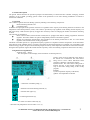
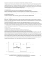
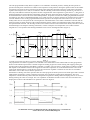
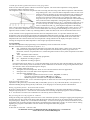
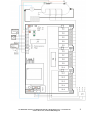
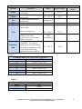
INTIEL
THE ELECTRONICS ON YOUR SIDE
Electrical boiler controller
INT0140
User’s Manual
tel.:00359 596 333 66 ||| fax:00359 596 325 80 ||| [email protected] ||| www.intiel.com
9 Peter Beron Str, Pomorie 8200, Bulgaria
1
I. Technical description
The present manual describe the operation principle and functionality of electrical boiler controller, managing nominal
capacities of up to 60kW, providing general control of the parameters of one water heating installation in relation to
environment conditions.
1. Operation
The Controller regulates the water heating system by affecting to the following components:
Electrical heating elements and
Circulation pump
In fact the main principle of the operation is based on a regulation of the capacity of the heating elements in relation to the
temperature in the heated premises (rooms). The control is provided by step regulation of the heating element capacity of 2
kW (respectively 4 kW when the capacity is bigger than 30 kW) by means of changing the number of switched on heating
sections.
The controller is consisted of:
Basic control module (electrical boiler module) that is equipped with built-in weekly programmer and boiler
regulator. The boiler module can operate independently without room thermo regulator.
Module for temperature measurement and assignation in the heated premises that in fact is a room thermo
regulator with or without outer weekly programmer.
The Boiler Controller operates as a proportional capacity regulator in compliance with the temperature. In fact that allows
using that part of the installed capacity, necessary for keeping the desired temperature level without over-expenditure of the
electrical energy surplus. The previous mentioned principle avoids any water temperature fluctuations in the electrical boiler
during the fixed operation regime that extends the life expectancy of the water heating components and increases its safety.
2. Regulation and signalization
2.1 Front panel – figure 1.
- The front panel is a LCD display with a resolution of 128x64 (position 1)
а) days of the week are indicated in this field, as
the current one is underlined. The same field is
being used to show control indications about
emergency situations or about OFF regime;
б) Present time. The same field is being used to
indicate the start of the periods /operation and
stop/ of the boiler during setting of the weekly
program;
в) Menu;
г) Current operation capacity of the boiler;
д) Поле за изобразяване на икони:
- switched on circulation pump (1);
- switched on electrical heating elements (2);
- activated OFF regime (3);
- overheating thermostat (4);
- low water level in the boiler body (5);
- the boiler body temperature water is bellow 15°С (6).
tel.:00359 596 333 66 ||| fax:00359 596 325 80 ||| [email protected] ||| www.intiel.com
9 Peter Beron Str, Pomorie 8000, Bulgaria
2
е) Indication about equi-thermal curve, type of the room thermostat or selected manual mode for adjustment of Tset.
- Button OFF/AUTO. It switches on the system (boiler) in heating or long stay mode.
- Button INCR. It changes the values and options in the menu.
- Button SET, for selection and confirmation.
- Light indication about week program (position 2). It is being indicated in case of active period of the week program.
- Light indication about the state of the circulation pump (position 3). It is being indicated when the circulation pump is
switched on.
Figure 1
Room thermoregulator
Two positional digital display. It shows the current or assigned air temperature at the place where it is mounted.
The indication is in degrees centigrade.
Button ASSAIGNED/CURRENT temperature. It shows the assigned temperature which the system try to keep
in the premises or the present one.
Knob for defining of the desired temperature.
Operation mode and functions
3.1 OFF regime. It is used during continual boiler stop. It can be chosen by the button
AUTO/OFF on the front panel. When the Controller is in OFF regime, the heating elements
are switched off. The room thermostat does not affect to the general operation, but it measures
and shows the real room temperature. Also, during that regime the circulation pump starts for
10 minutes a day in order to avoid its blocking, due to a fur accumulating. Generally the OFF
regime is appropriate during long stop boiler operation, even during the winter. There is no
risk of water freezing in the systems, due to all activated protections.
Going into OFF regime can be done by means of pressing and keeping the button (for about 3 sec.), then the button is to be
released, as on the display at field “a” appears a notification about the relevant operation mode. In case of switched on
electrical elements during this mode, it starts their smooth stopping. On the display appears symbol (3) after the last
electrical element is being switched off.
3.2 AUTO regime. It provides a regular heating operation and it can be selected by the front
panel button AUTO/OFF. The heating element operation is provided by the selected program,
by means of the weekly programmer or by a signal of the room thermostat.
3.3 Circulation PUMP. The pump is started when at least one heating section is switched on or the boiler water exceeds 40
0
C. The circulation pump goes on operation until the accumulated energy in the boiler will be transmitted to the radiators
(until boiler temperature reaches 40 0C).
The pump will be started by force, when the boiler temperature drops bellow 15 0C in order to pass the whole water volume
in the system through the boiler temperature sensor. The pump operation is being indicated with symbol (1) at position 3 of
the display.
3.4 ELECTRICAL HEATING ELEMENTS. The maximal number of heating element sections
is 15. Their in serial switching is provided by connection to the next power supply phase in
order to ensure an symmetrical electrical circuit loading. Switching of more than one section will be performed
consecutively and each next one will be connected with 3 sec. delay in relation to
tel.:00359 596 333 66 ||| fax:00359 596 325 80 ||| [email protected] ||| www.intiel.com
9 Peter Beron Str, Pomorie 8000, Bulgaria
3
the previous one. In this way it can be provided a smooth loading or unloading of the circuit,
avoiding any current rushes. In case of switched on at least one electrical heating section on the display appears symbol (2).
3.5 REGULATION. The regulation of the heating capacity is fulfilled by room thermo regulator, outdoor temperature and
adjusted equi-thermal curve, or manually by fixing Tset. As much as the real temperature becomes closer to the boiler one,
more heating sections will be switched off. In case both temperatures are equalized there will be kept the necessary number
of heating elements that is to provide the desired temperature level.
3.6 Weekly programmer. It defines the operation and stop time periods, according adjusted program.
4. PROTECTIONS
4.1 Thermal protection of the boiler body. It is provided by electro-mechanical emergency
thermostat, which boundary temperature level is not adjustable and it is preliminary fixed by the manufacturer.
REACTION. All heating elements will be switched off by force, in case its fixed boiler temperature will be exceeded. The
circulation pump will continue working for 10 minutes and will stop after that. On the display appears symbol (4)
OVERHEATING. The thermal protection cannot be restored by itself. It has to be restored manually only after eliminating
the reason about its activation.
4.2 Protection against low volume of the water content in the boiler body. Due to different reasons
the water volume in the boiler and whole heating system can be decreased, because of
evaporation, leakages and so on and the water level in the boiler body to be decreased bellow the admissible level for boiler
proper and safety operation.
REACTION. All heating elements and the circulation pump will be switched off after activating of the above mentioned
protection. As a result of that protection on the display appears symbol (5) LOW WATER LEVEL. The protection waits for
40 seconds after restoring the
water volume and afterwards smoothly switches on the necessary heating elements.
4.3 Protection against freezing the water in the boiler, pipes and radiators. It is being activated only in OFF regime.
REACTION: The circulation pump starts by force and constantly to operate if the boiler water temperature drops bellow 15
0
C. Symbol (6) appears on the display All heating elements will be switched on smoothly(100%) if the boiler water is bellow
6 0C and that operation will continues until the temperature exceeds 9 0C. Then the heating will be switched off smoothly,
while the water temperature is kept bellow 15 0C. When the protection against overheating is activated the protection against
freezing is blocked.
5. Equipment versions and operation characteristics
5.1 Equipped with a built-in weekly programmer and without a room thermostat.
The built-in weekly programmer defines the time intervals for the boiler operation and its
pause in relation to the selected program. During the operation interval the boiler assignation
is adjusted manually as the fixed temperature is constant. During the pause interval the controller assignation is 20 0C that
means switched off heating elements. Concerning the present equipment version (with a built-in weekly programmer and
without a room thermostat) it is recommended the installation of thermostatic valves in each of the heated rooms, in order to
obtain an individual temperature regulation for each of them. The temperature of the boiler water is to be defined manually
by the costumer and it does not relate to the outdoor temperature, but the thermostatic valves affect to the controller and the
electrical capacity by fixing the dose of the consumed heating capacity. During an operation interval the boiler keeps the
water temperature level permanent by variable capacity percentage. The main disadvantage of this equipment version is that
due to the manual setting, the water temperature can be not enough or redundant high for following the room temperature
assignation fixed by thermostatic valves. The operation regime can be seen on the diagram on Figure 2
5.2 With an outer weekly programmable thermo regulator, like CM 51 (Honeywell).
tel.:00359 596 333 66 ||| fax:00359 596 325 80 ||| [email protected] ||| www.intiel.com
9 Peter Beron Str, Pomorie 8000, Bulgaria
4
The outer programmable weekly thermo regulator is to be installed in the heated premises, defining the time periods of
operation and the pause of the boiler in relation to the temperature in the premises. During the operation interval the number
of switched on electrical sections respectively the boiler water temperature depends on the time in which the room thermo
regulator will be kept in ON or OFF, as in relation to that the switching of the electrical heating elements is to be done in 3
min.(only if the difference between the present and max. assigned boiler water temperature is grater than 9 0C). The status of
the thermoregulator is being indicated on the display. During the pause interval the boiler assignation is fixed at 20 0C. It can
be fixed thermostatic valves in all rooms of the heated premises, except this one where the weekly programmable thermostat
is mounted. In case there is installed thermostatic valve in this room also, it must be opened to its maximum level in order to
avoid the influence to the weekly programmable thermostat operation. The temperature of the boiler water is to be fixed
anually and it does not correspond to the room temperature. The thermostatic valves affect to the Boiler Controller and the
electrical capacity by fixing the dose of the consumed heating capacity and the room temperature affects to the duration of
the operation boiler intervals. The advantage of thisversion is the convenient control of the boiler directly from the room and
the disadvantage is the frequent switching of the boiler, in order to keep the room temperature in accordance with the
assigned level. The operation of the heating installation can be seen on the diagram bellow (Figure 3).
25 С
tс ,tсз [ С]
18 С
15 С
15 С
t [s]
tк ,tКmax
Tkmax
20 С
t [s]
3 programmer.
5.3 With proportional room thermo regulator and built-inФиг.
weekly
The proportional room thermo regulator is to be installed in one of the heated rooms and the built-in weekly programmer
located on the indication panel of the Controller assigns the weekly program for a boiler starting and stopping. During the
operation interval the assignation of the Boiler Controller is variable. It is received by a signal of the room thermo regulator
and depends on the difference between the assigned and real boiler temperature. It can be fixed thermostatic valves in all
rooms of the heated premises, except this one where the room thermo regulator is mounted. In case there is an installed
thermostatic valve in this room, it must be opened to its
maximum level. During each of the operation intervals of the program, the boiler operates in the fixed regime and a maximal
adapted water temperature, in order to keep the assigned by the room thermo regulator boiler temperature. The room
temperature variation indirectly affects the boiler temperature assignation as during autumn and spring there is no excessive
heating as during the winter it is enough. The over expenditure is eliminated and this version is the most economical one,
keeping the recourses of the installation. Its operation is shown on Figure 4.
tel.:00359 596 333 66 ||| fax:00359 596 325 80 ||| [email protected] ||| www.intiel.com
9 Peter Beron Str, Pomorie 8000, Bulgaria
5
5.3 With equi-thermal regulation and built-in weekly programmer.
In this case the controller operates without a room thermo regulator. The water boiler temperature is being adjusted
according the outdoor temperature sensor.
The assignation of the water boiler temperature starts increasing with decreasing of the outdoor temperature within defined
range starting from +20°С. The water boiler temperature reaches its max. level
(Tkmax) at the lower boundary level of the equi-thermal range (Toutdoor-min.
see figure 5). The desired equi-thermal curve depends on premise insulation
and it has to be selected in relation to the curve number from Table 2. The
range from -20 up to +20 0C is to be selected about premises with small heating
losses, where the hottest temperature of the heating water is being reached
when the outdoor temperature drops to -20 0C. Temperature ranges from +5 up
to +20 0C and 0 up to +20 0C are being adjusted for premises with big heat
losses, as warehouses, halls, etc., where highest temperature of the heating
water is being reached when the outdoor temperature drops down to +5 or 0 0C. The default setting is from -20 up to +20 0C
(curve 6). The outdoor temperature sensor is to be mounted at the outer north part of the building, in a way that it is not
exposed to direct sun shine or other way of heating radiation, which can affect to the correct measurement of the sensor.
5.5 The controller can be equipped with a domestic hot water temperature sensor, as it provides domestic hot water
preparation, as the control is being provided by the implemented thermostat in the controller. In this case the number of
switched on electrical heating elements depends on the difference between the assigned Tbset and current water tank
temperature Tb. The current domestic hot water temperature is being indicated on the display at the place of Tset, as
reaching the assigned water tank temperature is with a higher priority than the heating.
6. Programming
The controller adjustment and programming is to be fulfilled by means of buttons INC and SET.
B means of button INC is to be selected (see point 2.1 “в”):
Sett – adjustment of the assigned temperature in the water tank Tbset (when it is being used a system with a
domestic hot water preparation); Max. water temperature in the boiler body Tkmax; Type of the room
thermostat, selection of equi-thermal curve, manual assignation of the necessary water temperature in the boiler
body;
Time – adjustment of date and time;
Pr.N(Y) – switches the function – weekly programmer;
Pr.1 – adjustment of weekly program 1;
Pr.2 – adjustment of weekly program 2;
Press SET button (for at about 3 sec.) to start the adjustments, as the relevant value will start blinking. The change of
the values can be done by means of INC button, as the confirmation of the desired one by pressing SET button.(note:
date and time values do not blink during their changes).
Order of setting within Sett menu :
1.
Setting the water tank temperature Tbset. In case of need for domestic hot water preparation;
2.
Setting the max. level of the boiler water temperature Tkmax;
3.
Selection of the regulation way:
Equi-thermal regulation and selection of a curve (EQ Line, see Table 2)
Type of the room thermo regulator (TR Type, see Table 3)
Manual assignation of the boiler water temperature (Manual)
4.
Adjustment of Tset, in case of manual assignation. In all the rest cases Tset is being defined automatically.
Order for setting in Time menu
Adjustment of the present day of the month (DD), month (MM), year (YY), day of the week (DOW). The symbol in “a”
field starts blinking during entering the day of the week, as its changing is to be done by means of INCR button.
Weekly programmer function – deactivation and activation
By means of keeping pressed SET button in menu Pr.N(Y), it starts blinking, as by means of INCR button it is being
changed respectively to Pr.N – as the function is deactivated and even having an adjusted program it will not be fulfilled;
Pr.Y – the function is activated. The confirmation is to be done by means of SET button.
Way for setting the two week programs Pr.1 and Pr.2
Setting the starting time (beginning of the interval for a start of the boiler operation), setting the stopping time (beginning of
the pause interval), days of the week, during which the program will be activated. It can be selected all days of the week,
only working days, holiday ones, as well without selected days – as in this case the program will not be activated. If at one
program the time for starting/stopping of the boiler coincided, then the stopping has a priority. In case the time for starting
regarding two programs is same then a valid one remains the assignation of the first program.
For example:
P1 time ON= P1 time OFF – valid is P1 OFF
tel.:00359 596 333 66 ||| fax:00359 596 325 80 ||| [email protected] ||| www.intiel.com
6
9 Peter Beron Str, Pomorie 8000, Bulgaria
P1 time ON= P2 time ON – valid is P1 ON
II. Electrical connection
1.
Terminals (Figure 6)
1.1 Terminal about circulation pump connection – X14. Its is being used for connection of the circulation pump
with operation supply voltage ~220V/50Hz and nominal current up to 8A.
1.2 Terminal for connection of proportional room thermo regulator – X9.
It is being used for connection of proportional room thermo regulator with three core cable 3x0,75mm2
X9.1 – current signal 0-20mA
X9.2 – common terminal
The power supply of the thermo regulator is being provided by terminal X7.2 for +16V DC, as jumper J3 is to
be fixed preliminary in position 2.
1.3 Terminal for a connection of a contact room thermo regulator – X12;
1.4 Terminal for domestic hot water preparation – X11;
1.5 Terminal for a connection of water tank temperature sensor – X10 (type Pt-1000 non polar one);
1.6 Terminal for a connection of outdoor temperature sensor – X7 (type Pt-1000 non polar one). Jumper J3 is to be
fixed preliminary in position 1;
1.7 Terminal for a connection for boiler water temperature – X6 (type Pt-1000 non polar one);
1.8 Terminal for a connection of water level sensor in the boiler body – X8(ДН);
1.9 Terminal for a connection of overheating (blocking thermostat) – X1(БТ);
1.10 Terminal for a connection of operation power supply - 220V/50Hz - Х4;
1.11 Terminal for a connection of electrical heating elements – X2, X3 and X5. The phase is to be connected to the
heating elements through relays as the other terminals of the heating elements are to be connected to neutral.
The nominal current trough each of those outputs is 16A.
1.12
Terminal J1 (figure 6)
This terminal is being used for connection of 20 core wire from the front panel.
2.
2.1
2.2
Jumpers
Jumper J3. The position of this jumper defines if the boiler is to operate together with room thermo regulator
(placed in position 2), or with outdoor temperature sensor and equi-thermal regulation (placed in position 1)(see
figure 6)
Jumper J4. The protection against low water level of the boiler body is activated when the jumper is placed in
position 1, as when the jumper is in position 2, then this protection is deactivated.
tel.:00359 596 333 66 ||| fax:00359 596 325 80 ||| [email protected] ||| www.intiel.com
9 Peter Beron Str, Pomorie 8000, Bulgaria
7
tel.:00359 596 333 66 ||| fax:00359 596 325 80 ||| [email protected] ||| www.intiel.com
9 Peter Beron Str, Pomorie 8000, Bulgaria
8
Parameters and settings
Desribtion
Tbset
Tkmax
Tк
Tа
Тset
Description
Range
Default settings
Assigned temperature in the
water tank
Max. water temperature in the
boiler body
Current temperature in the
boiler body
Outdoor temperature
Assigned temperature in the
boiler body.
30 ÷ 60° С
40° С
40 ÷ 90° С
90° С
измерва се
-
измерва се
-
Manual assignation
30 ÷ 90°С
30° С
Self
calculated
-
5 ÷ -20° С
-10° С
Equi-thermal regulation;
Domestic hot water
preparation; Proportional
thermo regulator
During equi-thermal
regulation – the outdoor
temperature corresponding to
the highest temperature of the
water in the boiler body
(heating water)(see table 2)
Тoutdoor.
min
Customers’
settings
Table 2
T outdoor-min with equithermal regulation
Curve number
Range ° С
From +5 up to +20
1
From 0 up to +20
2
From - 5 up to +20
3
From -10 up to +20
4
From -15 up to +20
5
From -20 up to +20
6
Table 3
Room thermo regulator type
number
Type
1
2
Contact
Proportional
tel.:00359 596 333 66 ||| fax:00359 596 325 80 ||| [email protected] ||| www.intiel.com
9 Peter Beron Str, Pomorie 8000, Bulgaria
9
Notes:
__________________________________________________________
__________________________________________________________
__________________________________________________________
__________________________________________________________
__________________________________________________________
__________________________________________________________
__________________________________________________________
__________________________________________________________
__________________________________________________________
__________________________________________________________
__________________________________________________________
__________________________________________________________
__________________________________________________________
__________________________________________________________
__________________________________________________________
__________________________________________________________
________________________________________
VІ. Warranty
The warranty period is 24 months following the purchase date of the unit or its installation by an authorized
Engineering Company, but not exceeding 28 months after the production date. The warranty is extended to the malfunctions
that occur during the warranty period and are result of the production reasons or defective used parts.
The warranty does not relate to malfunctions corresponding to not-qualified installation, activities directed to
the product body interference, not regular storage or transport.
The repairs during the warranty period can be done after correct filling of the manufacturer warranty card
Warranty Card
Manufacturer: INTIEL
Product type
Production number
Production date
Electrical boiler controller INT0140
Dealer confirmation
Purchase date
Invoice number
Dealer’s name, address and stamp
Seller’s name and signature
tel.:00359 596 333 66 ||| fax:00359 596 325 80 ||| [email protected] ||| www.intiel.com
9 Peter Beron Str, Pomorie 8000, Bulgaria
10