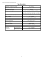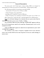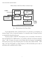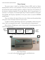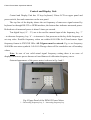
1
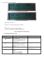
E-band Power Meter Operational Manual
ELVA-1 Microwave Ltd. S.A.
Mm-wave Division
e-mail: [email protected]
Internet: http://www.elva-1.com/
Technical Description and User Manual
E-band CW power meter DPM-12
s/n N-1204/21-T
1
E-band Power Meter Operational Manual
Specifications
Operating Frequency Range:
60-90GHz
Max measured power level:
20 mW (+13dBm)
Dynamic range (typ)
50 dB
Frequency set step:
1GHz, 0.5GHz, 0.25GHz, 0.2GHz,
0.1GHz, 0.05GHz, 0.02GHz, 0.01GHz
Measurement time (max):
0.5 sec
Input VSWR:
1.4:1 (max)
Interface port:
RS-232 (DB-9), GPIB
Power sensor port:
WR-12/UG-387/U
Power supply:
110 VAC
Software version
2620-110707
PC protocol
ELVA and SCPI
Ambient
air temperature:
conditions:
air humidity:
+5 to +40 deg. C
Up to 95 %
2
E-band Power Meter Operational Manual
General Description
The power meter with E-band power sensors (further DPM) was designed for
measurement of CW mm-wave power level within 60GHz - 90GHz frequency range.
The following possibilities of operating are provided in DPM:
- measurement of CW power level in Watt or in dBm
- setting of frequency step, control mode
- operating with PC using RS-232 port or GPIB ports
- setting of frequency step, indication of measured CW power level in Watt or in
dBm, control mode, “squeak ON/ OFF” mode through RS-232 or GPIB interface.
Note: To avoid sensor damage do not measure mm wave power more than the
MAX level indicated on power sensor: 20 mW (+13 dBm).
One can measure mm-wave power until sign “OVERLAOD” appears on the top
line of LCD. Alarm buzzer sounds at the same time. Measured power level is at the
bottom line of LCD.
If sign “OVERLOAD” appears one must decrease input mm-wave power until
“OVERLOAD” disappears.
The sensitivity of the sensor is frequency depended and the max measured
power can exceed the MAX level at some frequencies. It does not result in damage of
power sensor.
3
E-band Power Meter Operational Manual
Block-scheme of the Power Meter is shown in fig. 1.
110 VAC
Liquid Crystal
Display
Power supply
Power sensor
with EEPROM and
pre-amplifier
AD Converter
Controller
Video amplifier
Interface board
RS-232
or GPIB
Control and Display Unit.
Fig. 1. Block-scheme of the Power Meter.
To get right absolute value of measured power it is necessary to set frequency of
measured signal. Value of measured frequency is set manually using 12-buttons keyboard
or automatically through interface port.
Frequency format is XXX.XX. The frequency can be set manually in the format or
insert through RS-232 or GPIB interface. It is possible to shift the set frequency manually
using ‘*’ and ‘#’ buttons. One press on the buttons shifts the frequency correspondingly
down and up on one step. Step of frequency has a few fixed values within 0.01GHz…1GHz
range. Two line LCD displays set signal frequency in GHz and absolute power value in
microWatts (uW), milliWatts (mW) or dBm.
4
E-band Power Meter Operational Manual
Power Sensor
The power sensor is based on Zero-Biased Detector (ZBD) with Low Barrier
Schottky Diode of ELVA-1 Ltd. manufacture. The power sensor provides high sensitivity,
fast measurement speed, and quick response to changes of input power. The sensitivity of
the detector is frequency depended. To get right absolute value of measured power it is
necessary to set frequency of measured signal using 12-bottons keyboard on front panel.
The amplitude and frequency dependences of the power sensor are stored in EEPROM
installed inside.
There is an isolator at the input of the power sensor. Isolator provides good matching
of the power sensor with output of mm-wave power source.
To improve sensitivity and decrease noise level a pre-amplifier is built in the power
sensor. That is very important when small (< 10 microwatt) power is being measured.
Block-scheme of E-band power sensor is shown in fig 2. Outward appearance of the
sensor is presented in fig.3.
60-90GHz
Input
Waveguide
Attenuator
Zero Biased
Detector
Pre-amplifier &
EEPROM
+5 VDC
Signal
Ground
Fig. 2. Block-scheme of E-band Power Sensor
2
1
Fig 3. Power Sensor
1- Case with Zero-Biased Detector and Pre-amplifier with EEPROM inside,
2 – Mm-wave input
5
E-band Power Meter Operational Manual
Control and Display Unit.
Control and Display Unit has 12 keys keyboard, 2-lines LCD on upper panel and
power switch, fuse and connectors on the rear panel.
The top line of the display shows the set frequency of mm-wave signal entered by
keyboard or through RS-232 or GPIB interface; the bottom line indicates measured power.
Refresh rate of measured power is about 2 times per second.
Ten digital keys (‘0’…’9’) are to be used for manual input of the frequency, key ‘*’
– to decrease frequency, key ‘#’ – to increase it. One pressure on the key shifts frequency at
set step value. Possible frequency values are within 60-90 GHz for E-band sensor. Input
frequency format is XXX.XX GHz. All 5 figures must be entered. E.g. to set frequency
90.00GHz one enters symbols: 0-9-0-0-0.Wrong values will be rounded to one of boundary
values.
Note. In case of not valid actual signal frequency setting there is an error of
displayed mm-wave power because of non-flatness of calibration frequency curve.
Outward appearance of the power meter is shown in fig 4 and 5.
1
2
Fig.4 Upper Panel of the DPM-12 Power Meter
1 – Decreasing frequency key, 2 – Increasing frequency key
6
E-band Power Meter Operational Manual
4
1
2
5
6
3
Fig.5 Rear Panel of the DPM-12 Power Meter
1- GPIB port, 2 – RS-232 port, 3 – AC power socket, 4 - Power sensor connector, 5 –
Fuse, 6 – Power On/Off switch.
Frequency setting and receiving of measured power value can be realized using
interface ports.
Interface dialog consists of request (PC → DPM) and answer (DPM → PC) data
transmission. Request ASCII string represents current frequency in GHz and its format
must be 000.00 (6 chars, fixed point with leading and trailing zeroes). For example
frequency 62.50 GHz represents with string “062.50” gives request byte sequence 30 36 32
2E 35 30 (HEX values).
It has not have terminator like [CR LF]. Any excess byte will cause an error!
DPM answer depends on units what power level is measured in.
If measurements are performed in “Watt” units, the answer is:
ASCII string with current frequency in the same format as in input string, 7-th
character is separator – “space” (20 – Hex value), then goes the same string as power
displayed in DPM: 000.00mW/0.000mW or 000.00uW/0.000uW. In other words device
response is exactly the displayed string without any terminators (14 chars).
Chars in pos. 4,7,14 are constant and can be used to check if response is correct. The
first six chairs mean set frequency. The rest chairs do power value.
Decimal point in power value is not fixed!
7
E-band Power Meter Operational Manual
For “dBm” units the answer is: ASCII string with current frequency in the same
format as in input string, 7-th character is separator – “space” (20 – Hex value), then goes
the same string as power displayed in DPM: +/-00.00dBm/ or +/-0.000 dBm. In other
words device response is exactly the displayed string without any terminators (17 chars).
Chars in pos. 4, 7, 15, 16, 17 are constant and can be used to check if response is
correct. The first six chairs mean set frequency. The rest chairs do power value.
Decimal point in power value is not fixed!
Examples:
1) 12.34 μW at frequency 62.50GHz gives answer string 30 36 32 2E 35 30 20 31 32
2E 33 34 75 57 (HEX values).
2) -10.25 dBm at frequency 75.50GHz gives answer string 30 37 35 2E 35 30 20 2D
31 30 2E 32 35 20 64 42 6D (HEX values).
8
E-band Power Meter Operational Manual
Automatic setting of power meter operational modes:
Note: If “PC control mode” has been already set symbol * presents in LCD.
The DPM automatically turns to “PC control mode” if a command comes into
DPM from a PC. To leave “PC control mode” press any key.
Automatic setting of DPM operational modes can be provided through RS-232 or
GPIB interface of a PC.
- send to DPM control and display unit 6-bytes command through RS-232 or GPIB
port: BCDEFG
1 byte is “B” (“42” hex) – to choose set mode
“C”- 2-nd byte – “1” – for “Tab1”, “2” – for “Tab2” – to choose point of measured
power. “C” must be “1” in this model.
“D”- 3-rd byte – “0” or “1” or “2” or “3” or “4” or “5” or 6 or “7” to choose
frequency step: 10MHz, 20MHz, 50MHz, 100MHz, 200MHz, 250MHz, 500MHz, 1GHz
correspondingly
“E”- 4-th byte – “0” – “Watt” units for power indication, “1” – “dBm” units
“F”- 5-th byte – “0” –PC control OFF, “31” – PC control ON – to choose control
mode
“G”- 6-th byte – “0” – Squeak OFF, “1” – Squeak ON - to choose alarm squeak
mode
Symbols “0”, “1”,…”7” corresponds to “30”, “31”…”37” in HEX format.
There is a possibility to read with PC current mode of DPM, for this:
- send to DPM block 6-bytes command through RS-232 or GPIB port: AXXXXX,
1-st byte is A(“41”) – to choose check mode
Bytes “X” from 2-nd to 6-th can have any symbols;
The reply from DPM is “ACDEFG”,
Symbol “A” as in the request. Bites from “C” to “G” as above.
“C”- means “Tab”1” or “Tab”2”
9
E-band Power Meter Operational Manual
“D”- means “frequency step”
“E”- means units of measurements: “Watt” or “dBm”
“F”- means “PC control ON or OFF”. Must be ON
“G”- means “squeak ON or OFF”
For Example:
1) On request A12345 (41 31 32 33 34 35 in HEX value) DPM reports current
settings:
For example: Settings “Tab”1”, Frequency step 20MHz, “dBm” units, PC control
ON, “Squeak ON” DPM gives answer string 41 31 31 31 31 31 31
2) On request B10000 (42 31 30 30 30 30 in HEX value) DPM sets following
settings: “Tab”1”, Frequency step 10MHz, “Watt” units, PC control OFF, Squeak OFF”
Serial interface:
Data format –8 data bits, no parity, 1 stop bit ( 8N1 ).
Connection speed – 1200 bps.
Connection cable:
Really only 3 wires are used; case ground recommended for safety.
The power meter with GPIB interface requires MODEM cable.
GPIB interface:
The Serial interface ↔ GPIB card of ICS Electronics model 4806 tested with GPIB
card AX5488 with default jumper settings.
http://www.icselect.com/pdfs/4806_ds.pdf
http://www.icselect.com/
Device is configured for proper operation.
Factory default GPIB address - 4.
DPM GPIB configuration and operation commands.
Device is configured for proper operation, so the only thing to be changed in it's settings is GPIB address we left factory default ‘4’.
10
E-band Power Meter Operational Manual
Command strings and responses given in apostrophes to separate them from spaces and comments. Really
there mustn’t be apostrophes.
GPIB configuration
Action
Command string
Set new GPIB
‘SYST:COMM:GPIB:ADDR 11'
address 11
Address will be changed after 30 mSec delay.
Set baud rate 1200,
'SYST:COMM:SER:BAUD 1200;UP’
update UART
Device works only at baud rate 1200.
Set baud rate 1200,
'SYST:COMM:SER:BAUD 1200;UP;BAUD?’
update UART and
response: ‘1200’
query the value
Set RS232 timeout
'SYST:COMM:SER:TIME 2500'
2.5 sec
Recommended value
Set factory default 'CAL:DEF'
settings
Save
current
‘*SAV 0’
settings
GPIB operation
Action
Command string
Get power at
frequency
081.25GHz
‘081.25’ (format‘000.00’, 6 chars)
response(after approx. 1sec delay):
‘081.25 2.345mW’ or
‘081.25 0.000uW’ (microWatts)
Response string is exactly like string on DPM display.
Decimal point in power value is not fixed.
Warning
Do not
forget it!
!!! This set
Baud=9600
Warning
Terminator
mode must
be OFF (see
demo
source)*
* To set proper terminator mode for DPM GPIB interface card the following driver function call is used
(Pascal with AX5488 library):
ibeol(GPIB_ADDRESS,1{out_mode=1},oeol,strlen(oeol),
1{in_mode=1},ieol);
where oeol – any string, ieol – any char – with mode=1 they are void.
For other GPIB card function may differs – see manual for your card driver.
11
E-band Power Meter Operational Manual
Power Meter Operating:
1. Connect the Control and Display Unit of Power Meter and the Sensor.
2. Connect the 110 VAC adapter plug of DPM Control and display unit to a power
point. Then put AC switch ON. Wait for loading the DPM:
- Lines with number of software will appear on the screen. Fig.6.
Fig.6 Loading DPM screen
Then tests of power sensor and software are doing.
Note: The 2620-110707 version supports two protocols for control through PC.
“ELVA”- normally used with RS-232 interface
“SCPI ” – with GPIB interface. List of SCPI commands is included in the manual
below (see Appendix 1).
Read pages 14-15 and make sure the right protocol has been set for control
If the tests have been successfully passed screens as in Fig.7 and in Fig.8 are
following.
Fig.7 Test of power sensor has been done OK
12
E-band Power Meter Operational Manual
Fig.8 Test of software has been finished and OK
- If symbol “Fa” appears in screen as in Fig.9 and alarm squeak sounds it means that
connection between DPM and Power Sensor is unreliable.
Fig.9 Failed sensor tests screen
In this case one must switch DPM OFF and disconnect Power Sensor. Then connect the
Power Sensor properly with using screws on power sensor connector (DB-9) and switch the
DPM Control and Display unit again. If it is necessary one should repeat the operation until
the line Program OK (Fig.8) appears on screen. One can skip tests pressing any key.
Next screen shows two lines with current settings of the DPM Control and display
unit block. The settings are the same which was at the moment when the DPM was
switched OFF at last session.
13
E-band Power Meter Operational Manual
If it is necessary to set default settings one should keep the key “5” pressed during
switching ON and release it after two alarm squeaks.
Default settings are (Fig.10):
upper line: Tab1, step 1, W
lower line: SCPI
Fig.10 Screen with default settings of DPM
SCPI control format has been set
The values mean:
“Tab 1”- mode 1. Only this mode is available for this model.
“Step 1” – step 10 MHz (the smallest step)
“W”- indication in Watt units (uW, mW).
“Local SCPI”- PC control with SCPI protocol.
The DPM indicator block can be controlled with PC using “ ELVA” or “SCPI” protocol.
Check which “SCPI” or “ ELVA” control protocol has been set. It can be read when DPM
starts. SCPI has been set if screen as in Fig. 10.
Fig.11 ELVA control format has been set
3.
To check current control protocol or change control protocol:
-Press any key
-Insert symbols 992
14
E-band Power Meter Operational Manual
One of two types of screen appears:
I
Fig. 12 Current control format “SCPI”
Fig. 13 Current control format “ELVA”
Choose a) or b) below
a)
-Press key * if current control format satisfies
b)
-Press any key except * to change format.
-Press key * if indicated control format satisfies
The DPM Power meter is ready for operation if lines with frequency and power values are
displayed like in Fig.14
Frequency of measured signal Measured power level
#Mode (#Tab)
Fig.14 Power meter is ready for measurements
If display like on fig 15 appears (symbol * or #* or sign “READY TO START”), as shown
on the Fig 15, it means that DPM is in the automatic mode at the moment. To leave the
mode one should press any key.
15
E-band Power Meter Operational Manual
Fig 15. Power meter is in automatic mode
4 Choose measurement mode (Watt or dBm), for this:
- press any key;
- insert “997” code using keyboard
- press “0” for choosing Watt mode
- press any key, except “*” for choosing dBm mode
- press “*” to leave the mode
5 Choose TAB Number (TAB1 or TAB2) (mode number), for this:
- press any key;
- insert “999” code using keyboard
- press “1” for choosing TAB1
- press “2” for choosing TAB2
- press “*” to leave the mode
ATTENTION: Only one mode (Tab1=Tab2) is provided in this DPM model type.
6 Choose control and squeak mode (squeak ON or squeak OFF), for this:
16
E-band Power Meter Operational Manual
- press any key;
- insert “996” code using keyboard
- press consistently any key except “3” and “*” for choosing manual mode. Line
“Remote Off” means manual mode. In this mode squeak is always ON.
- press consistently any key except “3” and “*” for choosing control mode through
RS-232 or GPIB interface of a PC without squeak. Line “Remote On” means RS232 or GPIB without squeak mode ON.
- press consistently key “3” for choosing control mode through RS-232 or GPIB
interface of a PC with squeak. Line “Remote On #” means RS-232 or GPIB
interface with squeak mode ON.
- - press “*” to leave the mode. Sign “Remote READY TO START” or two lines
FREQUENCY/POWER appear in LCD (sign “*” or “*#” in right upper corner of
LCD means set automatic mode (Fig 15.)).
7 Connect input of the sensor to a source of mm-wave CW power.
8 In manual mode
8.1 choose frequency step, for this:
- press any key;
- insert “998” code using keyboard;
- press consistently any key, except “*” for choosing frequency step; Example:
Symbols 50 means frequency step 0.50GHz;
- press “*” to leave the mode.
8.2 Set frequency of measured signal in GHz, for this:
- press any key to get input frequency mode. Keep the key pressed until underline
sign appears. Presence of underline sign in LCD means frequency setting mode.
- insert frequency. Underline shows what symbol is being set. Frequency format is
XXX.XX GHz. All 5 figures must be entered. If right frequency value is not determined,
the absolute value of measured power will be wrong because output signal of power sensor
is frequency depended.
17
E-band Power Meter Operational Manual
- use key ‘*’ to shift the frequency down and key ‘#’ to shift it up on one step.
Frequency step is:
1GHz, 0.5GHz, 0.25GHz, 0.2GHz, 0.1GHz, 0.05GHz, 0.02GHz,
0.01GHz. How to set frequency step, read in the item 8.1 above.
8.3 Frequency value without underline sign in LCD means measuring mode.
8.4 Read the value of the measured power in LCD.
9. In automatic mode:
9.1 Connect PC with DPM RS-232 or GPIB port;
9.2 There is a possibility to check current mode of DPM as it written above, for this:
- by using software for checking
RS-232 or GPIB port send to DPM 6-byte
command: 1 byte - A(“41”) – to choose check mode
2 - 6 byte - any meanings;
9.3 There is a possibility to set mode of DPM as it written above, for this:
- send to DPM 6- through RS-232 or GPIB port byte command: 1 byte - B(“42”) –
to choose set mode
2 byte – “31” – Mode TAB1, “32” – Mode TAB2 – to choose mode.
Note: Only one mode (Tab1=Tab2) is provided in this DPM model. Use Tab1.
3 byte - “30” – 1, “31” – 2, “32” – 10, “33” – 10, “34” – 20, “35” – 25, “36” –
50, “37” – 100, - to choose frequency step
4 byte – “30” – “Watt” units, “31” – “dBm” units – to choose measurement
mode
5 byte – “30” – PC control OFF, “31” – PC control ON – to choose control
mode (manually or automatically)
6 byte – “30” – Squeak OFF, “31” – Squeak ON - to choose alarm squeak mode
9.4 Run softwear; Use ICS 4086 data sheet if needful
10. To leave automatic mode and proceed to manual mode
- press any key;
11. Use switch ON/OFF if one needs to reset the power meter.
Note: Do not switch the power meter ON/OFF if input mm-wave power exists at
power sensor input.
18
E-band Power Meter Operational Manual
Power Sensors calibration
E-band power sensor with DPM indicator block were calibrated at ELVA-1 lab with
ELVA-1’s reference power meters.
Calibration setup is shown in fig.16.
POWER METER
UNDER
CALIBRATION
POWER
SENSOR
REFERENCE
POWER METER
CONTROL
PC
POWER
SENSOR
Directional coupler
(calibrated)
Calibrated
attenuator
SWEEPING
OSCILLATOR
Fig.16 Power meter calibration setup
A sweeping oscillator provides mm-wave signal within full operating bandwidth of
the power sensors. MM-wave power was measured with reference power meter and
power meter under calibration at the same time. The calibration is being done
automatically with frequency step 0.2GHz. Correction factors are obtained and
loaded into EEPROM memory of power sensor under calibration.
Obtained test data of power level measured with two power meters (reference and
calibrated power sensors) after the calibration are presented in Tables 1.
Linearity tests of calibrated power sensors are presented in Tables 2.
19
E-band Power Meter Operational Manual
E-BAND POWER SENSOR
Table 1
F, GHz
Reference power
meter reading, uW
Calibrated power
meter reading, uW
Error, %
60
63
69
72
75
77
80
83
86
90
14110
16730
15630
20680
17240
4449
7661
5296
10870
14480
13900
16440
15730
20590
17170
4500
7719
5372
10910
14490
-1.4
-1.7
0.6
-0.4
-0.4
1.1
0.7
1.4
0.4
0.1
Table 2
Set attenuation, dB
F, GHz
0
5
10
15
20
Input Power, dBm
60
13.0
Linearity Error, dB
63
12.6
Linearity Error, dB
69
12.2
Linearity Error, dB
72
13.0
Linearity error, dB
75
12.7
Linearity Error, dB
77
7.2
Linearity error, dB
80
9
Linearity Error, dB
83
7.8
Linearity error, dB
86
10.3
Linearity Error, dB
90
Linearity error, dB
11.8
8.0
2.9
-1.9
-6.9
0
0.1
-0.1
-0.1
7.5
2.5
-2.4
-7.4
0.1
0.1
0
0
7.1
2.1
-2.8
-7.8
0.1
0.1
0
0
8.0
3.0
-2.0
-6.9
0
0
0
-0.1
7.7
2.7
-2.4
-7.3
0
0
0.1
0
2.2
-2.7
-7.7
-12.6
0
-0.1
-0.1
-0.2
3.9
-1.1
-6.2
-11.2
0.1
0.1
0.2
0.2
2.8
-2.2
-7.3
-12.4
0
0
0.1
0.2
5.3
0.2
-4.8
-9.9
0
0.1
0.1
0.2
6.7
1.7
-3.2
-8.2
0.1
0.1
0
0
20
E-band Power Meter Operational Manual
Appendix 1
Control of DPM power meter with SCPI protocol
Software version #110707
1. Switch DPM power meter ON.
2. Immediately after switching ON make sure the software version 110707 is used
Software version 110707 is loading
3. Check if SCPI control format is set. It can be read when DPM starts
SCPI control format has been set
ELVA control format has been set
To check current control format or change control format:
-Press any key
-Insert symbols 992
One of two types of screen appears:
21
E-band Power Meter Operational Manual
Current control format SCPI
Current control format ELVA
Choose a) or b) below
a)
-Press key * if current control format satisfies
b)
-Press any key except * to change format.
-Press key * if indicated control format satisfies
List of commands of SCPI format
1. Commands SYST2 (system)
Command
SYST2:***
syst2:beep:stat
off
syst2:beep:stat
on
syst2:beep:stat?
syst2:pres
Description
Respond
Turn Buzzer off
Buzzer does not sound (is off)
when a command receives at
remote mode
Turn Buzzer on
Buzzer sounds (is on) when a
command receives at remote
mode
Query of Buzzer status
Default DPM settings:
Tab1
Frq_step=1 (10 MHz)
Indication in uW/mW
22
on , Buzzer is on
off , Buzzer is off
E-band Power Meter Operational Manual
syst2:err?
SENS:***
sens:corr:tabl 1
sens:corr:tabl 2
sens:corr:tabl?
sens:freq
[xxx.xx]
examples:
sens:freq 91
sens:freq 091
sens:freq 91.0
sens:freq 091.00
sens:freq?
CALC:***
calc:aver:coun
[1…250]
calc:aver:coun?
UNIT:***
unit:pow dbm
unit:pow w
unit:pow?
READ:***
read?
fetc?
Manual control
syst:beep stat off, aver:count 50,
disp:enab off
0, No error
Query to type of last error
After the command error bite gets -100, Command error
-128, Numeric data not
0
allowed
-365, Time out error
Set mode Tab1 (for sensors with
directional coupler only)
Set mode Tab2 (for sensors with
directional coupler only)
Query of status Tab
1 , Tab1 is set
2 , Tab2 is set
Setting of frequency of measured
signal
Query of set frequency
91.00
Setting of number of
measurement points averaging
Query of set number of averaging
50
Setting of indication of power
level in dBm
Setting of indication of power
level in uW/mW
Query of type of power
measurement unit
W, power level in uW/mW
DBM, power level in dBm
Start of measurements and
receiving data
Reading of result of last done
measurement (without new
23
0.185 UW, measured power
level or
-37.3 DBM, measured power
level
0.185 UW, measured power
level or
E-band Power Meter Operational Manual
process of measurement)
DISP:***
disp:enab off
disp:enab on
disp:enab?
gtl
Display does not refresh
measurement information at
REMOTE(RS_control) mode
Display indicates actual
measurement information at
REMOTE(RS_control) mode
Display operation status
-37.3 DBM, measured power
level
on , Display indicates actual
data (is on)
off , Display does not refresh
data (is off)
Setting of manual control
(Go To Local control)
Notes:
DPM display unit with GPIB interface used ICS Electronics 4806 board
http://www.icselect.com/pdfs/4806_ds.pdf
http://www.icselect.com/
The board uses commands SYSTem, STATus, CALibrate, DIAGnostic and all IEE-488.2
Сommon Commands
Command of SYST2:*** type is used for DPM control
Only brief format of commands is allowed. Example: sens:aver:coun 50
Entire format is not allowed: Example:sensor:average:counts 50
Format of a command allows using Capital or lower-case letters
Command with forward colon “:” is wrong. Example: :disp:enab?. Correct disp:enab?
All commands have to have symbol LF (line feed, 0xA) in the end
Switching from Manual mode to Remote (RS_control) mode makes automatically if a
command through GPIB/ RS-232 interface appears. There is symbol “*” in LCD (14-th
symbol in 1-st line) if REMOTE mode is ON (despite if disp:enab? is off).
Frequency format in command and respond is numerical. Format with 2 symbols after
decimal point. Examples: 93.00, 105.20
Power level format with uW/mW or dBm units. Examples: 0.185 UW, 0.185 MW , -37.3
DBM.
If set frequency value is out of admissible range, the value has not been accepted and
changed and error appears -128, "Numeric data not allowed”. Can be read upon query.
Code of last error is kept in DPM and can be read with command syst2:err? After the
command the error bite gets 0.
The error byte gets 0 also if send commands: syst2:pres or gtl or DPM is switching ON.
If REMOTE(RS_control) is on, switching of DPM off and next on makes disp:enab? off
(i.e. Display does not refresh indicated data)
24