1
iQpump Controller
User Manual
Document Number: TM.iQp.06 PRG: 0034 ~ 003X
2
YASKAWA TM.iQp.06 iQpump Controller User Manual
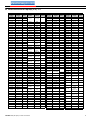
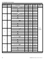
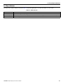
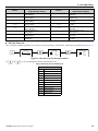
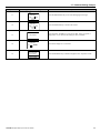
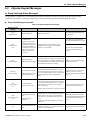
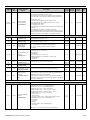
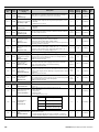
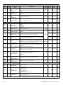
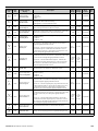
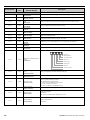
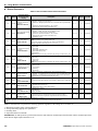
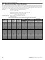
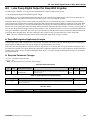
iQpump Software Changes
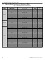
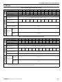
Table 1.1 Modified iQpump Default Settings
Parameter No.
■
Parameter Name
Original Default Setting
PRG: 0033
(VSP130033 and below)
New Default Setting
PRG: 0034
(VSP130034 and above)
5.0 s
3.0 s
0
2
b5-03
Integral Time Setting
PI I Time
b5-12
PI Feedback Reference Missing Detection Selection
PFb los Det Sel
b5-14
PI Feedback Loss Detection Time
PFb los Det Time
1.0 s
2.0 s
C1-01
Acceleration Time
Accel Time 1
25.0 s
20.0 s
C1-02
Deceleration Time
Decel Time 1
25.0 s
10.0 s
L5-01
Number of Auto Restart Attempts
Num of Restarts
0
5
L5-03
Maximum Restart Time After Fault
Max Restart Time
10.0 s
20.0 s
P1-05
Start Level Delay Time
S-Lvl Delay Time
0s
1s
P1-06
Minimum Pump Frequency
Min Pump Freq
35.0 Hz
40.0 Hz
P2-03
Sleep Delay Time
Sleep Delay Time
10 s
5s
P3-09
Pump 2 Frequency Shutdown Level
P2 Freq Shd Lvl
35.0 Hz
40.0 Hz
P3-10
Pump 3 Frequency Shutdown Level
P3 Freq Shd Lvl
35.0 Hz
40.0 Hz
P4-05
Thurst Bearing Frequency
Thrust Freq
0.00 Hz
30.0 Hz
P5-02
Hand Reference
Hand Reference
0.00
40.0 Hz
P9-15
Remove Delay Time
Remove Dly Time
5s
10 s
P9-16
Stabilization Time
Stabilization Time
1s
3s
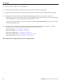
Miscellaneous Items:
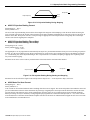
• In the previous software version, the Thrust Bearing Accel Time (P4-04) and Thrust Bearing Decel Time (P4-06) were set
based on the time for the drive to reach maximum frequency, just like the standard accel / decel time settings. In the new
version, they are set based on the time for the drive to reach the Thrust Frequency (P4-05).
• PID Trim Mode (b5-01 = 3) is deleted. The new b5-01 maximum setting is 2.
• C6-01 is deleted and the drive is internally fixed to setting 2 (Normal Duty 2).
• The C6-02 preset carrier frequency settings are modified. C6-04 and C6-05 are deleted. Certain C6-03 setting ranges are
prohibited. Models which previously had a default C6-03 setting or 5.0 kHz, now have a default setting of 5.1 kHz.
• The upper limit of Start Level (P1-04) is decreased from 6000.0 to 999.9
• The MODBUS / Memobus addresses for Monitors U1-96 ~ U1-99 have changed.
Monitor
Original Address
(Hex)
New Address
(Hex)
U1-96
0726
072A
U1-97
0727
072B
U1-98
0728
072C
U1-99
0729
072D
YASKAWA TM.iQp.06 iQpump Controller User Manual
3
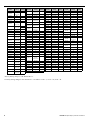
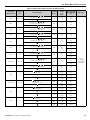
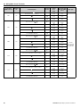
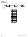
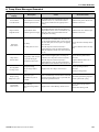
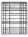
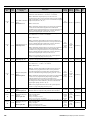
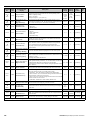
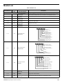
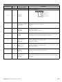
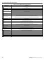
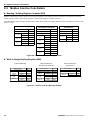
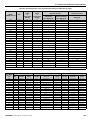
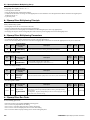
Table 1.2 Pump Quick Setup
Original Quick Start Menu
PRG: 0033
(VSP130033 and below)
Parameter No.
4
Parameter Name
New Quick Start Menu
PRG: 0034
(VSP130034 and above)
Parameter No.
Parameter Name
b1-01
Frequency Reference Selection
Reference Source
REMOVED FROM QUICK START MENU
b1-02
Run Command Selection
Run Source
REMOVED FROM QUICK START MENU
b5-12
PI Feedback Reference Missing Detection Selection
Fb los Det Sel
REMOVED FROM QUICK START MENU
b5-13
PI Feedback Loss Detection Level
Fb los Det Lvl
REMOVED FROM QUICK START MENU
b5-14
PI Feedback Loss Detection Time
Fb los Det Time
REMOVED FROM QUICK START MENU
C1-01
Acceleration Time
Accel Time 1
REMOVED FROM QUICK START MENU
C1-02
Deceleration Time
Decel Time 1
REMOVED FROM QUICK START MENU
d1-01
Start Level Delay Time
S-Lvl Delay Time
E2-01
Motor Rated Current
Motor Rated FLA
E2-01
Motor Rated Current
Motor Rated FLA
E2-04
Number of Motor Poles
Number of Poles
E2-04
Number of Motor Poles
Number of Poles
L5-01
Number of Auto Restart Attempts
Num of Restarts
REMOVED FROM QUICK START MENU
L5-03
Maximum Restart Time After Fault
Max Restart Time
REMOVED FROM QUICK START MENU
P1-02
System Units
System Units
REMOVED FROM QUICK START MENU
P1-03
Feedback Device Scaling
Fb Dev Scaling
P1-03
Feedback Device Scaling
Fb Dev Scaling
P1-04
Start Level
Start Level
P1-04
Start Level
Start Level
P1-05
Start Level Delay Time
S-Lvl Delay Time
REMOVED FROM QUICK START MENU
P1-07
Low Feedback Level
Low Fb Lvl
REMOVED FROM QUICK START MENU
P1-08
Low Feedback Level Fault Delay Time
Low Lvl FLT Time
REMOVED FROM QUICK START MENU
P1-09
High Feedback Level
High Fb Lvl
REMOVED FROM QUICK START MENU
P1-10
High Feedback Level Fault Delay Time
Hgh Lvl FLT Time
REMOVED FROM QUICK START MENU
P1-11
Maximum Set-point Difference
Max Set-point Diff
REMOVED FROM QUICK START MENU
P1-12
Not Maintaining Set-point Time
Not Maint SP Tm
REMOVED FROM QUICK START MENU
P1-14
Prime Loss Level
Prime Loss Lvl
REMOVED FROM QUICK START MENU
P2-01
Sleep Level Type
Sleep Lvl Type
REMOVED FROM QUICK START MENU
P2-02
Sleep Level
Sleep Level
REMOVED FROM QUICK START MENU
P2-03
Start Delay Time
Sleep Delay Time
REMOVED FROM QUICK START MENU
P2-10
Maximum Set-point Compensation
Max SP Comp
REMOVED FROM QUICK START MENU
P4-01
Pre-charge Level
Pre-charge Level
REMOVED FROM QUICK START MENU
P4-02
Pre-charge Frequency
Pre-charge Freq
REMOVED FROM QUICK START MENU
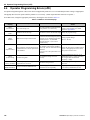
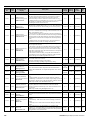
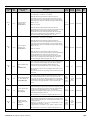
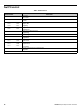
YASKAWA TM.iQp.06 iQpump Controller User Manual
Original Quick Start Menu
PRG: 0033
(VSP130033 and below)
Parameter No.
Parameter Name
New Quick Start Menu
PRG: 0034
(VSP130034 and above)
Parameter No.
Parameter Name
P4-03
Pre-charge Time
Pre-charge Time
REMOVED FROM QUICK START MENU
P4-04
Thrust Bearing Acceleration Time
Thrust Acc Time
REMOVED FROM QUICK START MENU
P4-05
Thrust Bearing Frequency
Thrust Freq
REMOVED FROM QUICK START MENU
P4-06
Thrust Bearing Deceleration Time
Thrust Dec Time
REMOVED FROM QUICK START MENU
P4-07
Feedback Fault Auto Restart Enable
Fdback Flt Rstrt
REMOVED FROM QUICK START MENU
P4-08
Protection Fault Auto Restart Enable
Prot Flt Restrt
REMOVED FROM QUICK START MENU
P4-09
Loss of Prime Maximum Restart Time After Fault
LOP Max Restrt T
REMOVED FROM QUICK START MENU
P4-10
Auto Mode Operator Run Power Down Storage
AMO PwDn-Storage
P5-01
Hand Mode Reference Source
Hand Mode Ref
REMOVED FROM QUICK START MENU
P5-02
Hand Reference
Hand Reference
REMOVED FROM QUICK START MENU
P4-10
P5-04
YASKAWA TM.iQp.06 iQpump Controller User Manual
Auto Mode Operator Run Power Down Storage
AMO PwDn-Storage
Hand Key Function Selection
Oper HAND Key
5
THIS PAGE INTENTIONALLY BLANK.
6
YASKAWA TM.iQp.06 iQpump Controller User Manual
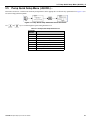
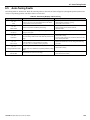
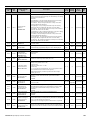
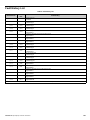
◆ Quick Reference for iQpump (P7U) <0034>
Parameter
Number
Factory
Setting
A1-00
A1-01
A1-03
A1-04
A1-05
b1-01
b1-02
b1-03
b1-07
b1-08
b1-11
b2-01
b2-02
b2-03
b2-04
b2-09
b3-01
b3-02
b3-03
b3-05
b3-14
b4-01
b4-02
b5-01
b5-02
b5-03
b5-04
b5-06
b5-07
b5-08
b5-09
b5-10
b5-12
b5-13
b5-14
b5-17
b5-32
b8-01
b8-04
b8-05
b8-06
C1-01
C1-02
0
2
0
0
0
0
0
0
0
0
0s
0.5 Hz
50 %
0.00 s
0.50 s
0%
2
120 %
2.0 s
0.2 s
1
0.0 s
0.0 s
1
2.00
3.0 s
100.0 %
100.00 %
0.0 %
0.00 s
0
1.0
2
0%
2.0 s
0.0 s
0.0 Hz
0
kVA Dep.
20 ms
0%
20.0 s
10.0 s
C1-03
C1-04
C1-05
C1-06
C1-09
C1-11
C2-01
C2-02
C4-01
C4-02
C6-02
User
Setting
Parameter
Number
Factory
Setting
C6-03
kVA Dep
d1-01
d1-02
d1-03
d1-04
d1-17
d2-01
d2-02
d2-03
d3-01
d3-02
d3-03
d3-04
0.00
0.00
0.00
0.00
0.00
100.0 %
0.0 %
0.0 %
0.0 Hz
0.0 Hz
0.0 Hz
1.0 Hz
E1-01
240 V
480 V
E1-03
E1-04
F
60.0 Hz
E1-05
230 V
460 V
E1-06
E1-07
60.0 Hz
3.0 Hz
E1-08
17.2 Vac
34.5 Vac
User
Setting
Parameter
Number
Factory
Setting
H3-08
H3-09
H3-10
H3-11
H3-12
H3-13
H4-01
H4-02
H4-03
H4-04
H4-05
H4-06
H4-07
H4-08
H5-01
H5-02
H5-03
H5-04
H5-05
H5-06
H5-07
H5-08
H5-09
L1-01
L1-02
L1-03
L1-04
L1-05
L2-01
L2-02
L2-03
L2-04
2
B**
100.0 %
0.0 %
0.30 s
0
2
100.0 %
0.0 %
8
50.0 %
0.0 %
0
0
1F
3
0
3
1
5 ms
1
0
2.0 s
1
8.0 min
3
1
0.20 s
2
kVA Dep
kVA Dep
kVA Dep
L2-05
Voltage
Class Dep
1
120 %
1
1
120 %
0.0 Hz
2.0 Hz
0
0
E1-09
1.5 Hz
E1-10
10.3 Vac
20.7 Vac
E1-11
E1-12
E1-13
E2-01
E2-03
E2-04
E2-05
F6-01
F6-02
F6-03
F6-05
H1-01
H1-02
0.0 Hz
0.0 Vac
0.0 Vac
kVA Dep
kVA Dep
2
kVA Dep
1
0
1
0
24
14
H1-03
3: 2-wire
0: 3-wire
L3-01
L3-02
L3-04
L3-05
L3-06
L4-01
L4-02
L4-05
L4-06
10.0 s
H1-04
80
L5-01
5
10.0 s
50.0 s
50.0 s
10.0 s
0.0 Hz
0.20 s
0.20 s
1.00
200 ms
kVA Dep
H1-05
H1-12
H1-13
H1-14
H1-15
H1-16
H2-01
H2-02
H3-02
H3-03
84
0.00 s
0.00 s
0.00 s
0.00 s
0.00 s
40
41
100.0 %
0.0 %
L5-02
L5-03
L6-01
L6-02
L6-03
L8-01
L8-02
L8-03
L8-05
L8-06
L8-07
0
20.0 s
0
15 %
10.0 s
0
95 ºC
4
1
kVA Dep
1
YASKAWA TM.iQp.06 iQpump Controller User Manual
User
Setting
Parameter
Number
Factory
Setting
L8-09
L8-10
L8-11
L8-12
L8-15
L8-18
L8-19
n1-01
n1-02
n3-01
n3-02
n3-03
n3-04
o1-01
o1-02
o1-05
o1-06
o1-07
o1-08
o2-01
o2-02
o2-03
o2-04
o2-05
o2-06
o2-07
o2-08
o2-10
o2-12
o2-14
o3-01
o3-02
P1-01
P1-02
P1-03
1
0
300 s
45 ºC
1
1
20.0 %
1
1.00
5%
150 %
1.0 s
40 s
6
1
3
1**
2**
91**
1
1
0
kVA Dep
0
1
0 hr
1
0 hr
0
0
0
0
0
1
00145
P1-04
0.0 (system
units P1-02)
P1-05
P1-06
1s
40.0 Hz
P1-07
0.0 (system
units P1-02)
P1-08
5s
155.0
P1-09
(system
units P1-02)
P1-10
P1-11
P1-12
P1-13
P1-14
P1-15
P1-16
P2-01
P2-02
User
Setting
2s
0.0 (system
units P1-02)
60 s
0.0 (system
units P1-02)
0.0 A
0
20 s
0
0.0
7
Parameter
Number
P2-03
P2-04
Factory
Setting
5s
0.0 (system
units P1-02)
P2-05
P2-06
P2-07
P2-08
10 s
0
300 s
0
P2-09
0.0 (system
units P1-02)
P2-10
0.0 (system
units P1-02)
P2-11
P2-12
P2-13
P2-14
0 rpm
15 rpm
5.0 s
5.0 s
P2-15
1.0 (system
units P1-02)
P2-16
1.5 (system
units P1-02)
P2-17
P2-18
P2-19
P2-20
P2-21
P2-22
P2-23
P2-24
P2-25
P3-01
P3-02
2.0 s
2.0 s
0
0.0
0.0
5.0 s
0.40 %
10.0 s
3.0 psi
0
59.0 Hz
P3-03
0.0 (system
units P1-02)
P3-04
P3-05
P3-06
P3-07
2s
0.0 (system
units P1-02)
5s
0.0 (system
User
Setting
Parameter
Number
Factory
Setting
P3-08
0.0 (system
units P1-02)
P3-09
P3-10
P3-11
40.0 Hz
40.0 Hz
2s
P3-12
0.0 (system
units P1-02)
P3-13
P3-14
0.0 Hz
0.0 (system
units P1-02)
P4-01
0.0 (system
units P1-02)
P4-02
P4-03
P4-04
P4-05
P4-06
P4-07
P4-08
P4-09
P4-10
P4-11
P4-12
P4-13
P4-14
P4-15
P4-16
0.00 Hz
0.0 min
1.0 s
30.0 Hz
1.0 s
0
0
0.2 min
0
0.2 min
0.00 Hz
0.0 min
0
0
24.0 hr
P4-17
(system
units P1-02)
P4-18
P4-19
P4-20
P4-21
P4-22
P4-23
P5-01
0.0 min
0.0 min
0
1
10 s
0.0 s
1
10.0
User
Setting
Parameter
Number
Factory
Setting
P5-02
P5-03
P5-04
P6-01
P6-02
P6-03
P6-04
P6-05
P6-06
P6-07
P6-08
P6-09
P6-10
P6-11
P6-12
P6-13
P6-14
P7-01
P7-02
P7-03
P7-04
P7-05
P7-06
P7-07
P7-08
P7-09
P7-10
P7-11
P8-01
P8-02
P8-03
P8-04
P8-05
P8-06
P8-07
P8-08
40.00 Hz
0
1
0.0 Gpm
0
0
0.0
10 s
0.0 min
1
3.0 min
0.0 gal
0 kgl
1
0.0
10 s
1
0
1
120 %
0.3 s
25.00 Hz
10 s
10 s
2.0 s
2.0 s
168.0 hr
2.0 s
0
100 psi
20.0 ft
10.0 ft
30.0 ft
0.00 Hz
0.0 ft
0.1 min
User
Setting
Parameter
Number
Factory
Setting
P8-09
P8-10
P8-11
P9-02
P9-03
P9-04
P9-05
P9-06
P9-07
P9-08
P9-09
1
2.00
5.0 s
0
24 hr
0
0
55.0 Hz
5s
0
56.0 Hz
P9-10
0.0 (system
units P1-02)
P9-11
P9-12
P9-13
10 s
0
40.0 Hz
P9-14
0.0 (system
units P1-02)
P9-15
P9-16
10 s
3s
P9-17
0.0 (system
units P1-02)
P9-18
P9-19
P9-20
P9-21
P9-22
P9-23
P9-24
P9-25
P9-26
P9-27
P9-28
P9-29
T1-02
T1-04
90.0 %
0
0
8
5
16
0s
08 h
4.0 s
0
2.0 s
2.0 s
kVA Dep
kVA Dep
User
Setting
units P1-02)
* Factory Setting changes to “B” when b5-01 = 1.
** Factory Setting changes to “B” when b5-01 = 1 as follows: o1-06 = 1, o1-07 = 38, o1-08 = 24.
8
YASKAWA TM.iQp.06 iQpump Controller User Manual
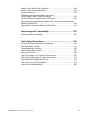
Table of Contents
Warnings and Cautions ........................................................... 13
Introduction .............................................................................. 15
Physical Installation................................................................. 17
iQpump Model Number and Enclosure Style ................................................ 18
Confirmations Upon Delivery ........................................................................ 19
Component Names ....................................................................................... 21
Exterior and Mounting Dimensions ............................................................... 23
Heat Loss Data ............................................................................................. 27
Checking and Controlling the Installation Site............................................... 28
Installation Orientation and Clearances ........................................................ 29
Removing and Attaching the Terminal Cover................................................ 30
Removing/Attaching the Digital Operator and Front Cover ........................... 31
Electrical Installation ............................................................... 35
Terminal Block Configuration ........................................................................ 36
Wiring Main Circuit Terminals........................................................................ 37
Control Wiring ............................................................................................... 46
Digital Operator ........................................................................ 57
Digital Operator Display ................................................................................ 58
Digital Operator Keys .................................................................................... 59
Drive Mode Indicators ................................................................................... 60
Drive Main Menu ........................................................................................... 62
Pump Quick Setup Menu (-QUICK-) H ........................................................ 67
Programming Menu (-ADV-).......................................................................... 68
Parameter Editing Example .......................................................................... 70
Start-Up ..................................................................................... 73
Start-Up ......................................................................................................... 74
iQpump Drive Quick Start-Up Procedures .................................................... 77
Basic Programming ................................................................. 89
iQpump Drive Basic Programming Parameters ............................................ 90
Pump Tuning ............................................................................................... 100
Pump Basic ................................................................................................. 128
Pump Protection.......................................................................................... 131
T1 Auto-Tuning ........................................................................................... 135
YASKAWA TM.iQp.06 iQpump Controller User Manual
9
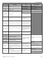
Diagnostics & Troubleshooting ............................................ 137
Fault Detection ............................................................................................ 138
iQpump Keypad Messages ......................................................................... 143
Alarm Detection........................................................................................... 145
Operator Programming Errors (oPE) .......................................................... 148
Auto-Tuning Faults ...................................................................................... 149
Digital Operator COPY Function Faults ...................................................... 150
Troubleshooting .......................................................................................... 151
Main Circuit Test Procedure ........................................................................ 155
Drive Date Stamp Information ..................................................................... 158
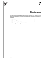
Maintenance............................................................................ 159
Periodic Inspection...................................................................................... 160
Preventive Maintenance.............................................................................. 161
Heatsink Cooling Fan Replacement............................................................ 162
Removing and Mounting the Terminal Card................................................ 164
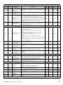
Parameters.............................................................................. 165
Parameter List............................................................................................. 166
Monitor List.................................................................................................. 197
Fault Trace List ........................................................................................... 200
Fault History List ......................................................................................... 201
Capacity Related Parameters................................................ 203
Drive Capacity............................................................................................. 204
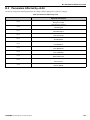
Parameters Affected by o2-04 .................................................................... 205
Capacity Related Parameter Values ........................................................... 206
Specifications ......................................................................... 209
Standard iQpump Drive Specifications........................................................ 210
Communication ...................................................................... 213
Using Modbus Communication ................................................................... 214
Modbus Function Code Details ................................................................... 218
Modbus Data Tables ................................................................................... 220
Modbus Self-Diagnosis ............................................................................... 225
Peripheral Devices ................................................................. 227
10
YASKAWA TM.iQp.06 iQpump Controller User Manual
Branch Circuit Short Circuit Protection........................................................ 228
Branch Circuit Overload Protection............................................................. 230
Peripheral Devices ...................................................................................... 230
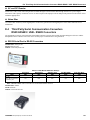
Third Party Serial Communication Converters
RS232-RS485 / USB - RS485 Converters.................................................. 231
SCADA Software for iQpump Drive (SW.iQp.01)........................................ 233
iQpump Drive Energy Savings Predictor with Carbon Footprint Calculation
Sotware (SW.ESP.03) ................................................................................. 233
iQpump Drive Harmonics Estimator (SW.HE.04)........................................ 233
Electromagnetic Compatibility.............................................. 235
Electromagnetic Compatibility..................................................................... 236
Quick Setup Procedures........................................................ 239
Set-up Procedures Included in this Appendix ............................................. 240
Well Draw Down Function........................................................................... 241
Sleep/Sleep Boost Function........................................................................ 245
Utility Delayed Start Function ...................................................................... 247
Start Level Function .................................................................................... 248
Low City Pressure or Low Suction Inlet Pressure ....................................... 250
Lube Pump Digital Output for Deep Well Irrigation ..................................... 251
iQpump Software Multiplexing Set-up......................................................... 252
First In First Out (FIFO) Description ........................................................... 262
Anti-No Flow Simplified Setup..................................................................... 263
YASKAWA TM.iQp.06 iQpump Controller User Manual
11
THIS PAGE IS INTENTIONALLY BLANK
12
YASKAWA TM.iQp.06 iQpump Controller User Manual
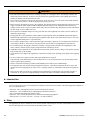
Warnings and Cautions
This Section provides warnings and cautions pertinent to this product, that if not heeded, may
result in personal injury, fatality, or equipment damage. Yaskawa is not responsible for
consequences of ignoring these instructions.
WARNING
YASKAWA manufactures component parts that can be used in a wide variety of industrial applications. The selection
and application of YASKAWA products remain the responsibility of the equipment designer or end user. YASKAWA
accepts no responsibility for the way its products are incorporated into the final system design. Under no circumstances
should any YASKAWA product be incorporated into any product or design as the exclusive or sole safety control.
Without exception, all controls should be designed to detect faults dynamically and fail safely under all circumstances.
All products designed to incorporate a component part manufactured by YASKAWA must be supplied to the end user
with appropriate warnings and instructions as to that part’s safe use and operation. Any warnings provided by
YASKAWA must be promptly provided to the end user. YASKAWA offers an express warranty only as to the quality of
its products in conforming to standards and specifications published in the YASKAWA manual. NO OTHER
WARRANTY, EXPRESS OR IMPLIED, IS OFFERED. YASKAWA assumes no liability for any personal injury,
property damage, losses, or claims arising from misapplication of its products.
YASKAWA TM.iQp.06 iQpump Controller User Manual
13
WARNING
• Read and understand this manual before installing, operating, or servicing this drive. All warnings, cautions, and
instructions must be followed. All activity must be performed by qualified personnel. The iQpump drive must be
installed according to this manual and local codes.
• Do not connect or disconnect wiring while the power is on. Do not remove covers or touch circuit boards while the
power is on. Do not remove or insert the digital operator while power is on.
• Before servicing, disconnect all power to the equipment. The internal capacitor remains charged even after the power
supply is turned off. Status indicator LEDs and Digital Operator display will be extinguished when the DC bus
voltage is below 50 Vdc. To prevent electric shock, wait at least five minutes after all indicators are OFF and measure
DC bus voltage level to confirm safe level.
• Do not perform a withstand voltage test on any part of the unit. This equipment uses sensitive devices and may be
damaged by high voltage.
• The iQpump drive is not suitable for circuits capable of delivering more than 100,000 RMS symmetrical amperes.
Install adequate branch short circuit protection per applicable codes. Refer to the specification. Failure to do so may
result in equipment damage and / or personal injury.
• Do not connect unapproved LC or RC interference suppression filters, capacitors, or overvoltage protection devices
to the output of the drive. These devices may generate peak currents that exceed iQpump drive specifications.
• To avoid unnecessary fault displays caused by contactors or output switches placed between iQpump drive and
motor, auxiliary contacts must be properly integrated into the control logic circuit.
• YASKAWA is not responsible for any modification of the product made by the user; doing so will void the warranty.
This product must not be modified.
• Verify that the rated voltage of the iQpump drive matches the voltage of the incoming power supply before applying
power.
• To meet CE directives, proper line filters and proper installation are required.
• Some drawings in this manual may be shown with protective covers or shields removed, to describe details. These
must be replaced before operation.
• Observe electrostatic discharge procedures when handling circuit cards to prevent ESD damage.
• The equipment may start unexpectedly upon application of power. Clear all personnel from the drive, motor, and
machine area before applying power. Secure covers, couplings, shaft keys, and machine loads before energizing the
drive.
• Please do not connect or operate any equipment with visible damage or missing parts. The operating company is
responsible for any injuries or equipment damage resulting from failure to heed the warnings in this manual.
◆ Intended Use
Drives are intended for installation in electrical systems or machinery.
For use in the European Union, the installation in machinery and systems must conform to the following product standards of
the Low Voltage Directive:
•
•
•
•
•
EN 50178, 1997-10, Equipping of Power Systems with Electronic Devices
EN 60201-1, 1997-12 Machine Safety and Equipping with Electrical Devices
Part 1: General Requirements (IEC 60204-1:1997)
EN 61010, 1997-11 Safety Requirements for Information Technology Equipment
(IEC 950:1991 + A1:1992 + A2:1993 + A3:1995 + A4:1996, modified)
◆ Other
The iQpump (P7U) drive is suitable for use on a circuit capable of delivering not more than 100,000 RMS symmetrical amperes,
240 Vac maximum (240 V Class) and 480 Vac maximum (480 V Class).
14
YASKAWA TM.iQp.06 iQpump Controller User Manual
Introduction
This Section describes the applicability of the Manual.
The iQpump (P7U) is a Pulse Width Modulated Drive for 3-Phase AC induction motors. This type of drive is also
known as an Adjustable Frequency Drive, Variable Frequency Drive, AC Drive, AFD, ASD, VFD, and Inverter.
The iQpump (P7U) is a variable torque AC drive, designed specifically for Simplex and Multiplex pumping
applications. The pump applications include Booster Systems, Submersible Deep Well, Fluid Storage Tanks,
Metering Pumps, Commercial and Residential Irrigation Systems.
The iQpump (P7U) sets a new benchmark for size, cost, performance, ease-of-use benefits, comprehensive pump and
motor protection features, and quality. The iQpump (P7U) includes numerous built-in features such as H/O/A
Operation, Selectable Pump Control Engineering Units, PI Control, Pump Basic Control, Pump Protection, MultiPump Control (Lead / Lag), and Pump Messaging Terminology.
The LCD keypad / operator is equipped with Hand / Off / Auto functions, copy feature, and 5 lines of display with 16
characters per line.
Built-in PI and pump specific functions and parameters allow the operator to setup specific control values for a wide
range of applications. The iQpump (P7U) will optimize the pump performance by automatically adjusting the pump
controller based on operating conditions of the pump; such as, process variable changes and pump protection
requirements. The P Group programming parameters are dedicated for pumping applications and provide for ease of
setup.
The iQpump (P7U) drive offers energy savings by controlling the flow rate and the number of operating pumps on the
system. The iQpump (P7U) can be configured using the most popular system control configurations including
Simplex, Duplex, and Triplex pumps systems. The iQpump (P7U) is the master controller with the ability to add
additional pumps on-line by controlling the digital I/O to each individual motor starter.
The iQpump (P7U) has an optional feature to replace the motors starters with additional drives for a more precise
pump control system.
This manual is applicable to the iQpump (P7U) Drives defined by models CIMR-P7U-107. This manual is subject
to change as product improvements occur. The latest version of the manual can be obtained from the Yaskawa. The
date shown on the rear cover is changed when revisions are made.
This manual may describe trademarked equipment, which is the property of other companies. These trademarks are
the property of the registered owner companies and may include the following:
• Modbus®, trademark of Schneider Automation, Inc.
Other Documents and Manuals are available to support special use or installation of this product. These documents
may be provided with the product or upon request. Contact Yaskawa Electric America, Inc. as required. Documents
may include the following:
•
•
•
•
TM.iQp.07 Programming Manual
TM.iQp.11 Modbus Manual
PumpScada Software and Manual included on CD ROM with product
Option Instructions included on CD ROM with product
YASKAWA TM.iQp.06 iQpump Controller User Manual
15
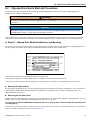
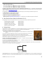
◆ Conventions Used in this Manual
■
Software Versions
Yaskawa recognizes the need to continuously improve product quality. This iQpump drive may receive feature enhancements in
the form of software or hardware changes in the future, and new functions may be added to the drive. When a new feature or
function is added, the software version <####> will be placed next to the feature or function.
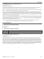
EXAMPLE:
A1-00 Language Selection
Setting
0
1
2
3
4
5
6
Description
English (factory default)
Japanese
Deutsche <0034>
Francais <0034>
Italiano <0034>
Espanol <0034>
Portugues <0034>
The example above shows that settings 2, 3, 4, 5, and 6 are added to parameter A1-00 for drive software version
PRG: <0034>.
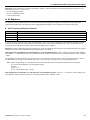
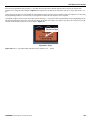
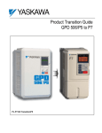
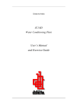
MODEL: CIMR-P7U2018
SPEC: 20181E
INPUT: AC3PH 200-240V 50/60Hz HD:84A ND:89A
OUTPUT: AC3PH 0-240V 0-400Hz HD:71A 27kVA ND:74.8A 29kVA
MASS: 11kg
O/N:
1W9911234560123
S/N:
PRG: 0034
FILE NO: E131457
DRIVE SOFTWARE
VERSION
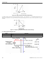
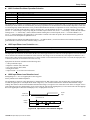
TYPE 1 ENCLOSURE IP20
Figure 1. Namplate with PRG software number
The “PRG:” number on the drive nameplate reflects the software version. The software version normally increases to a higher
number with newer versions.
16
YASKAWA TM.iQp.06 iQpump Controller User Manual
1
Physical Installation
This chapter describes the requirements for receiving and installing the iQpump drive.
1.1 iQpump Model Number and Enclosure Style . . . . . . . . . . . . . . . .
1.2 Confirmations Upon Delivery . . . . . . . . . . . . . . . . . . . . . . . . . . . . .
1.3 Component Names . . . . . . . . . . . . . . . . . . . . . . . . . . . . . . . . . . . . .
1.4 Exterior and Mounting Dimensions . . . . . . . . . . . . . . . . . . . . . . . .
1.5 Heat Loss Data . . . . . . . . . . . . . . . . . . . . . . . . . . . . . . . . . . . . . . . . .
1.6 Checking and Controlling the Installation Site . . . . . . . . . . . . . . .
1.7 Installation Orientation and Clearances . . . . . . . . . . . . . . . . . . . .
1.8 Removing and Attaching the Terminal Cover . . . . . . . . . . . . . . . .
1.9 Removing / Attaching the Digital Operator and Front Cover. . . .
YASKAWATM.iQp.06 iQpump Controller User Manual
18
19
21
23
27
28
29
30
31
17
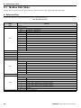
1.1 iQpump Model Number and Enclosure Style
1.1
iQpump Model Number and Enclosure Style
Table 1.1 iQpump Model Numbers and Enclosure Style
Input
Voltage
3-Phase
208-240 Vac
208-230 Vac
480 Vac
18
iQpump
Model-Number
CIMR-P7U❑-107
Enclosure Style
Rated
Output
Current
Nominal
Hp
20P4
NEMA Type 1 (IP20)
3.6
0.5 / 0.75
20P7
NEMA Type 1 (IP20)
4.6
1
21P5
NEMA Type 1 (IP20)
7.8
1.5 / 2
22P2
NEMA Type 1 (IP20)
10.8
3
23P7
NEMA Type 1 (IP20)
16.8
5
25P5
NEMA Type 1 (IP20)
23.0
7.5
27P5
NEMA Type 1 (IP20)
31.0
7.5 / 10
2011
NEMA Type 1 (IP20)
46.2
15
2015
NEMA Type 1 (IP20)
59.4
20
2018
NEMA Type 1 (IP20)
74.8
25
2022
NEMA Type 1 (IP20)
88.0
30
2030
NEMA Type 1 (IP20)
115.0
40
2037
Open Chassis (IP00)
162.0
50 / 60
2045
Open Chassis (IP00)
192.0
60 / 75
2055
Open Chassis (IP00)
215.0
75
2075
Open Chassis (IP00)
312.0
100 / 125
2090
Open Chassis (IP00)
360.0
125 / 150
2110
Open Chassis (IP00)
415.0
150
40P4
NEMA Type 1 (IP20)
1.8
0.5 / 0.75
40P7
NEMA Type 1 (IP20)
2.1
1
41P5
NEMA Type 1 (IP20)
3.7
1.5 / 2
42P2
NEMA Type 1 (IP20)
5.3
3
43P7
NEMA Type 1 (IP20)
7.6
5
45P5
NEMA Type 1 (IP20)
12.5
7.5
47P5
NEMA Type 1 (IP20)
17.0
10
49P0
NEMA Type 1 (IP20)
21.0
15
4011
NEMA Type 1 (IP20)
27.0
20
4015
NEMA Type 1 (IP20)
34.0
25
4018
NEMA Type 1 (IP20)
40.0
30
4024
NEMA Type 1 (IP20)
52.0
40
4030
NEMA Type 1 (IP20)
67.2
50
4037
NEMA Type 1 (IP20)
77.0
60
4045
NEMA Type 1 (IP20)
96.0
75
4055
NEMA Type 1 (IP20)
125.0
100
4075
Open Chassis (IP00)
156.0
125
4090
Open Chassis (IP00)
180.0
150
4110
Open Chassis (IP00)
240.0
200
4160
Open Chassis (IP00)
304.0
250
4185
Open Chassis (IP00)
414.0
300 / 350
4220
Open Chassis (IP00)
515.0
400 / 450
4300
Open Chassis (IP00)
675.0
500+
YASKAWA TM.iQp.06 iQpump Controller User Manual
1.2 Confirmations Upon Delivery
1.2
Confirmations Upon Delivery
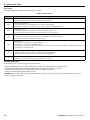
◆ Receiving Checks
Check the following items as soon as the iQpump drive is received.
Table 1.2 Receiving Checks
Item
Method
Has the correct iQpump drive model been delivered?
Check the model number on the nameplate on the right side of the iQpump drive.
Reconcile with packing slip and/or order information.
Is the iQpump drive damaged in any way?
Inspect the entire exterior of the iQpump drive to see if there are any dents, scratches or other damage
resulting from shipping.
Are any screws or other components loose?
Use a screwdriver or other tool to check for tightness.
If there are any irregularities in the above items, contact the shipping company, the distributor or representative who sold the iQpump
drive, or a Yaskawa office immediately.
The iQpump drive is thoroughly tested at the factory. Any damages or shortages evident when the equipment is received must be reported
immediately to the commercial carrier that transported the material. Shipping damage is not covered by the Yaskawa warranty. After
unpacking and inspecting for damage, verify that internal wire connections have not come loose during shipment by spot checking wire
terminations with a screwdriver or the appropriate tool.
iQpump drive storage must be in a clean and dry location. Maintain the factory packaging and provide covering as needed to
protect the iQpump from construction site dirt, water, debris and traffic prior to and during construction.
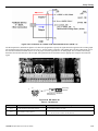
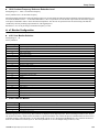
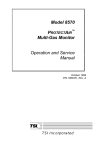
◆ Nameplate Information
A nameplate is attached to the right side of each iQpump drive. The following nameplate is an example for a standard iQpump drive.
■
Normal P7
Drive Model Number
Input Power Rating
Output Power Rating
Serial Number
UL File Number
■
MODEL:
CIMR-P7U2011
INPUT:
AC3PH 200-240V 50/60Hz 53A
SPEC: 20111A
OUTPUT: AC3PH 0-240V 0-120Hz 46.2A 18kVA
O/N:
MASS: 7.0kg
S/N: 1W06Z7123450001
PRG:0034
FILE: E131457
TYPE 1 ENCLOSURE
Drive Spec Number
Weight
IP20
P7 iQpump
YEA ITEM#: CIMR-P7U20111A-107
Drive Model Number
Input Power Rating
Output Power Rating
Serial Number
UL File Number
MODEL:
CIMR-P7U2011 SPEC: 20111A-U890107
INPUT:
AC3PH 200-240V 50/60Hz 53A
OUTPUT: AC3PH 0-240V 0-120Hz 46.2A 18kVA
O/N:
MASS: 7.0kg
S/N: 1W06Z7123450001
PRG:0034
FILE: E131457
TYPE 1 ENCLOSURE
Drive Spec Number
Weight
IP20
Note: The iQpump Drive Model Number and iQpump Drive Spec. Number are required to completely identify an iQpump Drive.
Figure 1.1 iQpump (P7U) Drive Nameplate
YASKAWA TM.iQp.06 iQpump Controller User Manual
19
1.2 Confirmations Upon Delivery
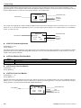
◆ Drive Model Numbers
The model number on the nameplate indicates the design specification, voltage, and rating of the iQpump drive in alphanumeric codes.
CIMR – P7 U 2 0 11*
AC Drive
iQpump Family
Spec
UL Specification
No.
U
No.
2
4
Rating
Voltage
3-phase, 208-240 Vac
* YEA Item #: CIMR-P7U20111A-107
3-phase, 480 Vac
Figure 1.2 iQpump Drive Model Number Structure
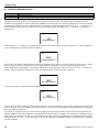
◆ Drive Enclosure and Revision Code
The iQpump drive SPEC number on the nameplate indicates the voltage, iQpump drive rating, enclosure type, and the revision code of
the iQpump drive in alphanumeric codes.
2 011 1 A U890107
No.
Voltage
2
4
3-phase, 208 - 240 Vac
VAU Number
Hardware Revision
3-phase, 480 Vac
Rating
No.
0
Enclosure Type
Open chassis (IEC IP00)
1
NEMA Type 1 (IEC IP20)
Figure 1.3 SPEC Number Structure
TERMS
Open Chassis Type (IEC IP00)
Protected so that parts of the human body cannot reach electrically charged parts from the front when
the iQpump drive is mounted in a control panel, also called (protected chassis).
TERMS
NEMA Type 1 (IEC IP20)
The iQpump drive is shielded from the exterior, and can thus be mounted to the interior wall of a
building (not necessarily enclosed in a control panel). The protective structure conforms to the
standards of NEMA Type 1 in the USA. All protective covers (Fig 1.4) must be installed to conform
with IEC IP20 and NEMA Type 1 requirements
20
YASKAWA TM.iQp.06 iQpump Controller User Manual
1.3 Component Names
1.3
Component Names
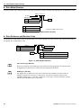
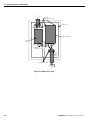
◆ Models CIMR-P7U20P4 through 2018 (25 HP @ 208 V / 240 V) and 40P4 through 4018
(30 HP @ 480 V)
The external appearance, component names, and terminal arrangement of the iQpump drive are shown in Figure 1.4 and Figure 1.5.
Top protective cover
Mounting hole
Front cover
Digital Operator
Diecast Heat Sink
Nameplate
Terminal cover
Bottom protective cover
Figure 1.4 iQpump Drive Appearance
Figure 1.5 Terminal Arrangement (Terminal Cover Removed)
YASKAWA TM.iQp.06 iQpump Controller User Manual
21
1.3 Component Names
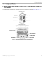
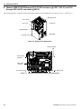
◆ Models CIMR-P7U2022 through 2110 (30 HP and above @ 208 V / 240 V) and 4030
through 4300 (40 HP and above @ 480 V)
The external appearance, component names, and terminal arrangement of the iQpump drive are shown in Figure 1.6 and Figure 1.7.
Mounting
holes
Mounting holes
Drive
cover
Drive cover
Front
cover
Front
cover
Cooling
Coolingfan
fan
Digital
Operator
Digital
Operator
Terminalcover
cover
Terminal
Nameplate
Nameplate
Figure 1.6 iQpump Drive Appearance
Charge indicator
Control circuit
terminals
Main circuit
terminals
Ground terminal
Ground terminal
Figure 1.7 Terminal Arrangement (Terminal Cover Removed)
22
YASKAWA TM.iQp.06 iQpump Controller User Manual
1.4 Exterior and Mounting Dimensions
1.4
Exterior and Mounting Dimensions
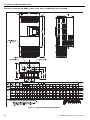
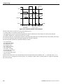
Dimensions: iQpump (P7U) (NEMA 1) 208 V / 240 V (3.6–74.8 AMPS) 480 V (1.8–40.0 AMPS)
FRONT VIEW
SIDE VIEW
MOUNTING HOLES
FOR "A" SIZE SCREW
AIR
H2
1.38 DIA.
(2) HOLES SIZE "J"
.87 DIA.
C
L
H1
H
B
AIR
W1
W2
F
BOTTOM VIEW
D
RATED
208V
240V
MODEL
CIMR-P7U -107
E
D1
W
RATED
INPUT
C
OUTPUT
CURRENT
(AMPS)
DIMENSIONS IN INCHES
NOMINAL
HP
MOUNTING
H1
W1
H
W
H2
W2
D
D1
A
B
C
E
F
J
APPROX.
WEIGHT
(LBS.)
20P41
3.6
10.47
4.96
11.02
5.51
.28
.28
6.30
1.54
#10
---
3.35
4.73
1.97
1.10
6.6
20P71
4.6
1
10.47
4.96
11.02
5.51
.28
.28
6.30
1.54
#10
---
3.35
4.73
1.97
1.10
6.6
21P51
7.8
2
10.47
4.96
11.02
5.51
.28
.28
6.30
1.54
#10
---
3.35
4.73
1.97
1.10
6.6
22P21
10.8
3
10.47
4.96
11.02
5.51
.28
.28
6.30
1.54
#10
---
3.35
4.73
1.97
1.10
6.6
23P71
16.8
5
10.47
4.96
11.02
5.51
.28
.28
7.09
2.32
#10
---
4.14
5.52
1.97
1.10
8.8
27P51
31.0
7.5-10
11.22
7.32
11.81
7.87
.28
.28
7.87
2.58
4.63
5.11
6.21
3.07
1.38
13.2
1/2 3/4-
1/4
6.21
3.07
1.38
15.4
6.65
3.94
1.73
24.2
5.79
6.65
3.94
1.73
24.2
3.35
4.73
1.97
1.10
6.6
---
3.35
4.73
1.97
1.10
6.6
#10
---
3.35
4.73
1.97
1.10
6.6
1.54
#10
---
3.35
4.73
1.97
1.10
6.6
7.09
2.32
#10
---
4.14
5.52
1.97
1.10
8.8
.28
7.09
2.32
#10
---
4.14
5.52
1.97
1.10
8.8
.28
.28
7.87
2.58
4.63
5.11
6.21
3.07
1.38
13.2
20111
46.2
15
11.22
7.32
12.20
7.87
.28
.28
7.87
2.58
1/4
4.63
20151
59.4
20
13.19
8.50
13.78
9.45
.30
.47
8.27
3.07
1/4
5.12
5.79
20181
74.8
25
13.19
8.50
14.96
9.45
.30
.47
8.27
3.07
1/4
5.12
20P41
3.6
1/2 3/4-
10.47
4.96
11.02
5.51
.28
.28
6.30
1.54
#10
---
20P71
4.6
1
10.47
4.96
11.02
5.51
.28
.28
6.30
1.54
#10
21P51
7.8
2
10.47
4.96
11.02
5.51
.28
.28
6.30
1.54
22P21
10.8
3
10.47
4.96
11.02
5.51
.28
.28
6.30
23P71
16.8
5
10.47
4.96
11.02
5.51
.28
.28
25P51
23.0
7.5
10.47
4.96
11.02
5.51
.28
27P51
31.0
10
11.22
7.32
11.81
7.87
1/4
20111
46.2
15
11.22
7.32
12.20
7.87
.28
.28
7.87
2.58
1/4
4.63
20151
59.4
20
13.19
8.50
13.78
9.45
.30
.47
8.27
3.07
1/4
5.12
20181
74.8
25
13.19
8.50
14.96
9.45
.30
.47
8.27
3.07
1/4
5.11
6.21
3.07
1.38
15.4
5.79
6.65
3.94
1.73
24.2
5.12
5.79
6.65
3.94
1.73
24.2
4.73
6.6
5.11
40P41
1.8
10.47
4.96
11.02
5.51
.28
.28
6.30
1.54
#10
---
3.35
1.97
1.10
40P71
2.1
1
10.47
4.96
11.02
5.51
.28
.28
6.30
1.54
#10
---
3.35
4.73
1.97
1.10
6.6
41P51
3.7
2
10.47
4.96
11.02
5.51
.28
.28
6.30
1.54
#10
---
3.35
4.73
1.97
1.10
6.6
42P21
5.3
3
10.47
4.96
11.02
5.51
.28
.28
7.09
2.32
#10
---
4.14
5.52
1.97
1.10
8.8
43P71
7.6
5
10.47
4.96
11.02
5.51
.28
.28
7.09
2.32
#10
---
4.14
5.52
1.97
1.10
8.8
45P51
12.5
7.5
10.47
4.96
11.02
5.51
.28
.28
7.09
2.32
#10
---
4.14
5.52
1.97
1.10
8.8
47P51
17.0
10
11.22
7.32
11.81
7.87
.28
.28
7.87
2.58
4.63
5.11
6.21
3.07
1.38
13.2
1/2 3/4-
480V
1/4
49P01
21.0
15
11.22
7.32
11.81
7.87
.28
.28
7.87
2.58
1/4
4.63
5.11
6.21
3.07
1.38
13.2
40111
27.0
20
11.22
7.32
11.81
7.87
.28
.28
7.87
2.58
1/4
4.63
5.11
6.21
3.07
1.38
13.2
40151
34.0
25
13.19
8.50
13.78
9.45
.30
.47
8.27
3.07
5.12
5.79
6.65
3.94
1.73
22
40181
40.0
30
13.19
8.50
13.78
9.45
.30
.47
8.27
3.07
5.12
5.79
6.65
3.94
1.73
22
1/4
1/4
FOR REFERENCE ONLY UNLESS PROPERLY ENDORSED.
IN ORDER TO ACHIEVE ADEQUATE COOLING
THE DRIVE MUST BE POSITIONED TO ALLOW A MINIMUM
OF FREE AIR SPACE OF 1.2 INCHES ON SIDES AND
5 INCHES TOP AND BOTTOM
Figure 1.8 Exterior and Mounting Dimensions
YASKAWA TM.iQp.06 iQpump Controller User Manual
23
1.4 Exterior and Mounting Dimensions
Dimensions: iQpump (P7U) (NEMA 1) 208 V / 240 V (88.0–115 AMPS) 480 V (52.0–125 AMPS)
APPROX.
WEIGHT
(LBS.)
CURRENT
Figure 1.9 Exterior and Mounting Dimensions
24
YASKAWA TM.iQp.06 iQpump Controller User Manual
1.4 Exterior and Mounting Dimensions
Dimensions: iQpump (P7U) (Protected Chassis) 208–230 V (162–415 AMPS) 480 V (156–304 AMPS)
FRONT VIEW
MOUNTING HOLES
FOR "A" SIZE SCREW
H2
H1
AIR
H
AIR
W2
W1
D1
D
W
RATED
INPUT
MODEL
CIMR-P7U
RATED
OUTPUT
CURRENT
DIMENSIONS IN INCHES
NOM.
HP
(AMPS)
208V
230V
480V
MOUNTING
H1
W1
H
W
H2
W2
D
D1
A
APPROX.
WEIGHT
(LBS.)
20370
162
50
22.64
9.84
23.62
14.76
.49
2.46
11.81
3.94
3/8
125
20450
192
60
22.64
9.84
23.62
14.76
.49
2.46
12.99
5.12
3/8
139
20550
215
75
27.56
12.80
28.54
17.72
.49
2.46
13.78
5.12
3/8
189
20750
312
100
27.56
12.80
28.54
17.72
.49
2.46
13.78
5.12
3/8
191
20900
360
125
32.28
14.57
33.46
19.69
.59
2.56
14.17
5.12
3/8
238
21100
415
150
33.66
17.52
34.84
.59
2.56
14.96
5.51
3/8
330
20370
162
50-60
22.64
9.84
23.62
14.76
.49
2.46
11.81
3.94
3/8
125
22.64
20450
192
75
22.64
9.84
23.62
14.76
.49
2.46
12.99
5.12
3/8
20750
312
100-125
27.56
12.80
28.54
17.72
.49
2.46
13.78
5.12
3/8
191
20900
360
150
32.28
14.57
33.46
19.69
.59
2.56
14.17
5.12
3/8
238
40750
156
125
27.56
12.80
28.54
17.72
.49
2.46
13.78
5.12
3/8
194
40900
180
150
27.56
12.80
28.54
17.72
.49
2.46
13.78
5.12
3/8
196
139
41100
240
200
32.28
14.57
33.46
19.69
.59
2.56
14.17
5.12
3/8
224
41600
304
250
33.66
17.52
36.06
22.64
.59
2.56
14.96
5.51
3/8
352
FOR REFERENCE ONLY UNLESS PROPERLY ENDORSED.
IN ORDER TO ACHIEVE ADEQUATE COOLING
THE DRIVE MUST BE POSITIONED TO ALLOW A MINIMUM
OF FREE AIR SPACE OF 1.2 INCHES ON SIDES AND
5 INCHES TOP AND BOTTOM
Figure 1.10 Exterior and Mounting Dimensions
YASKAWA TM.iQp.06 iQpump Controller User Manual
25
1.4 Exterior and Mounting Dimensions
Dimensions: iQpump (P7U) (Protected Chassis)
MOUNTING HOLES
FOR "A" SIZE SCREWS
AIR
H2
H1 H
W2
W1
W1
AIR
W
D1
D
RATED
INPUT
480V
MODEL
CIMR-P7U
RATED
OUTPUT
CURRENT
(AMPS)
D
D1
A
300-350
W1
10.63
W2
414
H1
50.00
H2
41850
51.38
27.95
.79
3.35
16.34
4.94
3/8
572
42200
515
400-450
50.00
10.63
51.38
27.95
.79
3.35
16.34
4.94
3/8
616
43000
675
56.70
14.37
58.07
36.06
.79
3.66
16.34
4.94
3/8
891
DIMENSIONS IN INCHES
NOM.
HP
500
MOUNTING
H
W
APPROX.
WEIGHT
(LBS.)
FOR REFERENCE ONLY UNLESS PROPERLY ENDORSED.
IN ORDER TO ACHIEVE ADEQUATE COOLING
THE DRIVE MUST BE POSITIONED TO ALLOW A MINIMUM
OF FREE AIR OF 1.2 INCHES ON SIDES AND
5 INCHES TOP AND BOTTOM
Figure 1.11 Exterior and Mounting Dimensions
26
YASKAWA TM.iQp.06 iQpump Controller User Manual
1.5 Heat Loss Data
1.5
Heat Loss Data
Table 1.3 200V Class Heat Loss Data
TYPE
CIMR-P7U-107
Drive
(Inverter)
Capacity
(kVA)
Rated
Output
Current
(A)
Cooling Fin Side
(W)
Internal
Unit Side (W)
Total
Watt Loss
(W)
Cooling Method
20P4
1.4
3.6
19
39
58
Self
20P7
1.8
4.6
26
42
68
Self
21P5
3.0
7.8
48
50
98
Self
22P2
4.1
10.8
68
59
127
Self
23P7
6.4
16.8
110
74
184
Fan
25P5
8.8
23
164
84
248
Fan
27P5
12
31
219
113
332
Fan
2011
18
46.2
357
168
524
Fan
2015
23
59.4
416
182
597
Fan
2018
29
74.8
472
208
680
Fan
2022
34
88
583
252
835
Fan
2030
44
115
883
333
1217
Fan
2037
62
162
1010
421
1430
Fan
2045
73
192
1228
499
1727
Fan
2055
82
215
1588
619
2206
Fan
2075
120
312
1956
844
2800
Fan
2090
140
360
2194
964
3157
Fan
2110
160
415
2733
1234
3967
Fan
Table 1.4 400V Class Heat Loss Data
TYPE
CIMR-P7U-107
Drive
(Inverter)
Capacity
(kVA)
Rated
Output
Current
(A)
Cooling Fin Side
(W)
Internal
Unit Side (W)
Total
Watt Loss
(W)
Cooling Method
40P4
1.4
1.8
14
39
53
Self
40P7
1.6
2.1
17
41
58
Self
41P5
2.8
3.7
36
48
84
Self
42P2
4.0
5.3
59
56
115
Fan
43P7
5.8
7.6
80
68
140
Fan
Fan
44P0
6.6
8.7
90
70
160
45P5
9.5
12.5
127
81
209
Fan
47P5
13
17
193
114
307
Fan
49P0
16
21
232
158
390
Fan
4011
21
27
232
158
390
Fan
4015
26
34
296
169
465
Fan
4018
30
40
389
201
590
Fan
4022
38
50.4
420
233
653
Fan
4024
40
52
691
297
989
Fan
4030
51
67.2
691
297
989
Fan
4037
59
77
801
332
1133
Fan
4045
73
96
901
386
1287
Fan
4055
95
125
1204
478
1682
Fan
4075
120
156
1285
562
1847
Fan
4090
140
180
1614
673
2287
Fan
4110
180
240
1889
847
2736
Fan
4132
200
260
2388
1005
3393
Fan
4160
230
304
2636
1144
3936
Fan
4185
315
414
2791
1328
3964
Fan
4220
390
515
3797
1712
5509
Fan
4300
510
675
5838
2482
8319
Fan
YASKAWA TM.iQp.06 iQpump Controller User Manual
27
1.6 Checking and Controlling the Installation Site
1.6
Checking and Controlling the Installation Site
Install the iQpump drive as described below and maintain optimum conditions.
WARNING
The iQpump drive heatsink temperature may exceed 158 °F (70 °C). Therefore, mount the iQpump drive to a surface
suitable for high temperature.
◆ Installation Site
Locate the iQpump drive as close as possible to the motor. Install the iQpump drive under the following conditions in UL Pollution
Degree 1 and 2 environments. This excludes wet locations where surfaces may become conductive due to moisture and contaminant
loading.
Table 1.5 Installation Site Specifications
Type
Ambient Operating Temperature
Humidity
Plenum Rated
NEMA Type 1
14 °F-to 104 °F (-10-to +40 °C)
95 %-RH-or-less-(no-condensation)
Yes
Open Chassis
14 °F-to 113 °F (-10 to +45 °C)
95 %-RH-or-less-(no-condensation)
No
Protective covers are attached to the top and bottom of the iQpump drive. It is recommended to remove the protective covers before
operating a CIMR-P7U2030 / 4055-107 iQpump drive and smaller in a panel to obtain the 113 °F (45 °C) ambient operating temperature.
Observe the following precautions when installing the iQpump drive:
•
•
•
•
•
•
•
•
in a clean location which is free from oil mist and dust.
in an environment where metal shavings, oil, water, or other foreign materials will not get into the iQpump drive enclosure.
in a location free from radioactive materials.
in a location free from harmful gasses and liquids.
in a location free from excessive vibration.
in a location free from chlorides.
in a location away from direct sunlight.
on a non-combustible surface.
◆ Controlling the Ambient Temperature
To enhance the reliability of operation, the iQpump drive should be installed in an environment free from extreme temperature variations.
If the iQpump drive is installed in an enclosure, use a cooling fan or air conditioner to maintain the internal air temperature below 113 °F
(45 °C).
◆ Protecting the iQpump Drive from Foreign Matter
During iQpump drive installation and project construction it is possible to have foreign matter, such as metal shavings or wire clippings,
fall inside the iQpump drive. To prevent foreign matter from falling into the iQpump drive, place a temporary cover over the iQpump
drive.
Always remove the temporary cover from the iQpump drive before Start-Up. Otherwise, ventilation will be reduced, causing the iQpump
drive to overheat.
28
YASKAWA TM.iQp.06 iQpump Controller User Manual
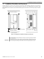
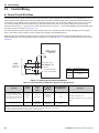
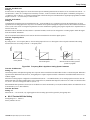
1.7 Installation Orientation and Clearances
1.7
Installation Orientation and Clearances
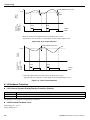
Install the iQpump drive vertically so as not to reduce the cooling efficiency. When installing the iQpump drive, always provide the
following installation clearances to allow normal heat dissipation. For 3HP, 208V / 240V (CIMR-P7U22P2-107 and below) or 2HP,
480V (CIMR-P7U41P-107 and below), ensure that the heatsink is against a closed surface to avoid diverting cooling air around the
heatsink.
4.75 in (120 mm. minimum)
4.75 in (120 mm. minimum)
Air
1.2 in
(30.5 MM.) min.
1.2 in
(30.5 mm. minimum)
4.75 in (50 mm. minimum)
Horizontal Clearance
1.2 in
(30.5 mm. minimum)
4.75 in (120 mm. minimum)
Air
Vertical Clearance
Figure 1.12 iQpump Drive Installation Orientation and Clearance
IMPORTANT
• The same clearance is required horizontally and vertically for both Open Chassis (IP00) and NEMA
Type 1 iQpump drives.
• Always remove the top and bottom protection covers before installing a CIMR-P7U2018 / 4018-107
and smaller iQpump drive in a panel. Always provide enough clearance for lifting eye bolts and the
main circuit wiring when installing a CIMR-P7U2022 / 4030-107 and larger iQpump drive in a panel.
YASKAWA TM.iQp.06 iQpump Controller User Manual
29
1.8 Removing and Attaching the Terminal Cover
1.8
Removing and Attaching the Terminal Cover
Remove the terminal cover to connect cables to the control circuit and main circuit terminals.
WARNING
Prior to removing any protective cover or wiring any part of the iQpump drive, remove all power sources, including
main input power and control circuit power. Wait a minimum 5 minutes after power removal, before removing any cover.
The charge lamp located within the iQpump drive should be off prior to working inside. Even if the charge lamp is off,
one must measure the AC input, output, and DC Bus potential to insure safe levels prior to resuming work. Failure to
adhere to this warning may result in personal injury or death.
◆ Removing the Terminal Cover
■
Models CIMR-P7U20P4 through 2018 (0.5 HP to 25 HP @ 208 V / 240 V) and 40P4 through 4018
(0.5 HP to 30 HP @ 480 V)
Loosen the screw at the bottom of the terminal cover, press in on the sides of the terminal cover in the directions of arrows 1, and then lift
up on the terminal in the direction of arrow 2. Refer to Figure 1.13.
■
Models CIMR-P7U2022 through 2110 (30 HP to 150 HP @ 208 V / 240 V) and 4030 through 4300
(40 HP to 500 HP @ 480 V)
Loosen the screws on the left and right at the top of the terminal cover, pull down the terminal cover in the direction of arrow 1 and then
lift up on the terminal cover in the direction of arrow 2. Refer to Figure 1.14.
Figure 1.1
1
2
Figure 1.13 Removing the Terminal Cover
Figure 1.14 Removing the Terminal Cover
◆ Attaching the Terminal Cover
After wiring the terminal block, attach the terminal cover by reversing the removal procedure.
For Models CIMR-P7U2018 / 4018-107 and smaller, insert the tab on the top of the terminal cover into the groove on the iQpump drive
and press in on the bottom of the terminal cover until it snaps into place.
For iQpump drives CIMR-P7U2022 / 4030-107 and larger, insert the tab on the top of the terminal cover into the groove on the iQpump
drive, and secure the terminal cover by lifting it up toward the top of the iQpump drive.
30
YASKAWA TM.iQp.06 iQpump Controller User Manual
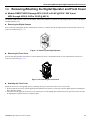
1.9 Removing/Attaching the Digital Operator and Front Cover
1.9
Removing/Attaching the Digital Operator and Front Cover
◆ Models CIMR-P7U20P4 through 2018 (0.5 HP to 25 HP @ 208 V / 240 V) and
40P4 through 4018 (0.5 HP to 30 HP @ 480 V)
For Models CIMR-P7U2018 / 4018-107 and smaller, remove the terminal cover and use the following procedures to remove the digital
operator and front cover.
■
Removing the Digital Operator
Press on the side of the digital operator in the direction of arrow 1 to unlock, then lift the digital operator in the direction of arrow 2 to
remove it as shown in Figure 1.15.
2
1
Figure 1.15 Removing the Digital Operator
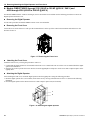
■
Removing the Front Cover
Press the left and right sides of the front cover in the direction of arrows 1 and lift the bottom of cover in the direction of arrow 2 to
remove it as shown in Figure 1.16.
1
2
Figure 1.16 Removing the Front Cover
■
Attaching the Front Cover
Mount the front cover to the iQpump drive by performing the steps to remove the front cover in reverse order.
1. Do not mount the front cover with the digital operator attached to the front cover; this may cause the digital operator to malfunction
due to imperfect contact.
2. Insert the tab of the upper part of the front cover into the groove of the iQpump drive and press the lower part of the front cover onto
the iQpump drive until the front cover snaps into place.
YASKAWA TM.iQp.06 iQpump Controller User Manual
31
1.9 Removing/Attaching the Digital Operator and Front Cover
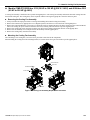
◆ Models CIMR-P7U2022 through 2110 (30 HP to 150 HP @ 208 V / 240 V) and
4030 through 4300 (40 HP to 500 HP @ 480 V)
For Models CIMR-P7U2022 / 4030-107 and larger, remove the terminal cover and then use the following procedures to remove the
Digital Operator and front cover.
■
Removing the Digital Operator
Use the same procedure for Models CIMR-P7U2018 / 4018-107 and smaller.
■
Removing the Front Cover
Loosen all screws on the front cover. Lift up at the location labeled 1 at the top of the control circuit terminal card and move in the
direction of arrow 2.
2
1
Figure 1.17 Removing the Front Cover
■
Attaching the Front Cover
Attach the front cover by reversing the procedure to remove it.
1. Confirm that the digital operator is not mounted on the front cover. Contact faults can occur if the cover is attached while the digital
operator is mounted to it.
2. Insert the tab on the top of the front cover into the slot on the iQpump drive and press in on the cover until it snaps into place on the
iQpump drive.
■
Attaching the Digital Operator
After attaching the front cover, mount the digital operator onto the iQpump drive using the following procedure.
1. Hook the digital operator at A (two locations) on the front cover by moving in the direction of arrow 1 as shown in the following
illustration.
2. Press the digital operator in the direction of arrow 2 until it snaps in place at B (two locations).
A
1
B
2
Figure 1.18 Mounting the Digital Operator
32
YASKAWA TM.iQp.06 iQpump Controller User Manual
1.9 Removing/Attaching the Digital Operator and Front Cover
IMPORTANT
• Do not remove or attach the Digital Operator or mount or remove the front cover using methods other
than those described above, damage to the Digital Operator or iQpump drive may occur.
• Never attach the front cover to the iQpump drive with the Digital Operator attached to the front cover.
Damage to the Digital Operator may occur. Always attach the front cover to the iQpump drive first,
and then attach the Digital Operator to the front cover.
YASKAWA TM.iQp.06 iQpump Controller User Manual
33
1.9 Removing/Attaching the Digital Operator and Front Cover
THIS PAGE INTENTIONALLY BLANK.
34
YASKAWA TM.iQp.06 iQpump Controller User Manual
2
Electrical Installation
This chapter describes wiring terminals, main circuit terminal connections, main circuit terminal
wiring specifications, control circuit terminals, and control circuit wiring specifications.
2.1 Terminal Block Configuration. . . . . . . . . . . . . . . . . . . . . . . . . . . . . 36
2.2 Wiring Main Circuit Terminals . . . . . . . . . . . . . . . . . . . . . . . . . . . . 37
2.3 Control Wiring . . . . . . . . . . . . . . . . . . . . . . . . . . . . . . . . . . . . . . . . . 46
YASKAWA TM.iQp.06 iQpump Controller User Manual
35
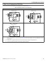
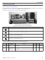
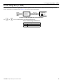
2.1 Terminal Block Configuration
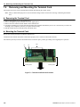
2.1
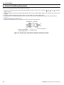
Terminal Block Configuration
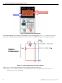
The wiring terminals are shown in Figure 2.1.
SN SC SP A1 A2 +V AC -V
E(G)
MP AC RP R+ R-
S1 S2 S3 S4 S5 S6 S7 FM AC AM IG S+ S-
M5 M6 MA MB MC
M3 M4 M1
M2
E(G)
Control circuit terminals
Main circuit terminals
Charge indicator
Ground terminal
Ground terminal
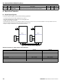
Models CIMR-_ _ _2018 (25 HP, 208/240V)/4018 (30 HP, 480V) and smaller
SN SC SP A1 A2 +V AC -V
E(G)
MP AC RP R+ R-
S1 S2 S3 S4 S5 S6 S7 FM AC AM IG S+ S-
M5 M6 MA MB MC
M3 M4 M1
M2
E(G)
Control circuit terminals
Charge indicator
Main circuit terminals
Ground terminal
Ground terminal
Models CIMR-_ _ _2022 (30 HP, 208/240V)/4030 (40 HP, 480V) and larger
Figure 2.1 iQpump Drive Terminal Configuration
36
YASKAWA TM.iQp.06 iQpump Controller User Manual
2.2 Wiring Main Circuit Terminals
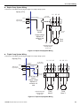
2.2
Wiring Main Circuit Terminals
◆ Applicable Wire Sizes and Closed-Loop Connectors
Select the appropriate wires and crimp terminals from Table 2.1 to Table 2.2.
Table 2.1 208-240 Vac Wire Sizes and Connector Specifications
Drive Model
CIMR-P7U❑-107
Nominal
HP
Terminal Symbol
Terminal
Screws
Clamping
Torque
lb. in.
(N•m)
Recommended
Wire Size
AWG
(mm2)
20P4
0.5 / 0.75
R/L1, S/L2, T/L3,
,
1,
2,
B1, B2, U/T1, V/T2, W/T3
M4
13.3
(1.5)
14
(2.1)
20P7
2
R/L1, S/L2, T/L3,
,
1,
2,
B1, B2, U/T1, V/T2, W/T3
M4
13.3
(1.5)
14
(2.1)
21P5
1.5 / 2
R/L1, S/L2, T/L3,
,
1,
2,
B1, B2, U/T1, V/T2, W/T3
M4
13.3
(1.5)
14
(2.1)
22P2
3
R/L1, S/L2, T/L3,
,
1,
2,
B1, B2, U/T1, V/T2, W/T3
M4
13.3
(1.5)
12
(3.3)
23P7
5
R/L1, S/L2, T/L3,
,
1,
2,
B1, B2, U/T1, V/T2, W/T3
M4
13.3
(1.5)
10
(5.3)
25P5
7.5
R/L1, S/L2, T/L3,
,
1,
2,
B1, B2, U/T1, V/T2, W/T3
M4
13.3
(1.5)
10
(5.3)
27P5
10
R/L1, S/L2, T/L3,
,
1,
2,
B1, B2, U/T1, V/T2, W/T3
M5
22.1
(2.5)
8
(8)
2011
15
R/L1, S/L2, T/L3,
,
1,
2,
B1, B2, U/T1, V/T2, W/T3
M5
22.1
(2.5)
6
(13.3)
M6
44.3
(5.0)
4
(21.2)
M5
22.1
(2.5)
6
(13.3)
M6
44.3
(5.0)
6
(13.3)
M8
88.5
(10.0)
2
(33.6)
M5
22.1
(2.5)
6
(13.3)
M6
44.3
(5.0)
4
(21.2)
M8
88.5
(10.0)
1
(42.4)
M6
45.1
(5.1)
4
(21.2)
M8
88.5
(10.0)
4
(21.2)
M8
88.5
(10.0)
1/0
(53.5)
M6
45.1
(5.1)
4
(21.2)
M8
88.5
(10.0)
2
(38)
R/L1, S/L2, T/L3,
2015
20
1,
2, U/T1, V/T2, W/T3
B1, B2
R/L1, S/L2, T/L3,
2018
,
25
,
1,
2, U/T1, V/T2, W/T3
B1, B2
R/L1, S/L2, T/L3,
,
1, U/T1, V/T2,
W/T3, R1/L11, S1/L21, T1/L31
2022
30
3
R/L1, S/L2, T/L3,
,
1 U/T1,
V/T2, W/T3, R1/L11, S1/L21, T1/L31
2030
40
YASKAWA TM.iQp.06 iQpump Controller User Manual
3
Wire
Type
600 Vac
UL Approved
vinyl-sheathed
or equivalent
37
2.2 Wiring Main Circuit Terminals
Drive Model
CIMR-P7U❑-107
2037
2045
Nominal
HP
50
60
Terminal Symbol
Terminal
Screws
Clamping
Torque
lb. in.
(N•m)
Recommended
Wire Size
AWG
(mm2)
R/L1, S/L2, T/L3,
,
1 U/T1,
V/T2, W/T3, R1/L11, S1/L21, T1/L31
M10
199
(22.5)
4/0
(100)
M8
88.5
(10.0)
4
(22)
M10
203.6
(23)
2/0
(67.4)
r/l1, s/l2
M4
12.4
(1.4)
14
(2.1)
R/L1, S/L2, T/L3,
,
1 U/T1,
V/T2, W/T3, R1/L11, S1/L21, T1/L31
M10
199
(22.5)
300
(152)
M8
88.5
(10.0)
4
(21.2)
M10
199
(22.5)
3/0
(85)
M4
12.4
(1.4)
14
(2.1)
M12
347
(39.2)
1/0 X 2P
(53.5 X 2P)
M10
199
(22.5)
1/0 X 2P
(53.5 X 2P)
M8
88.5
(10.0)
2/0
(67.4)
M10
199
(22.5)
4/0
(107.2)
M4
12.4
(1.4)
14
(2.1)
M12
347
(39.2)
4/0 X 2P
(80 X 2P)
M10
199
(22.5)
3/0 X 2P
(85 X 2P)
M8
88.5
(10.0)
2/0
(67.4)
M10
199
(22.5)
2/0 X 2P
(67.4 X 2P)
M4
12.4
(1.4)
14
(2.1)
M12
347
(39.2)
250 x2P
(127 x2P)
M12
347
(39.2)
4/0 X 2P
(107.2 X 2P)
M8
88.5
(10.0)
2/0
(67.4)
M12
347
(39.2)
2/0 X 2P
(67.4 X 2P)
M4
12.4
(1.4)
14
(2.1)
M12
347
(39.2)
300 X 2P
(152 X 2P)
M12
347
(39.2)
300 X 2P
152 X 2P
M8
88.5
(10.0)
2/0
(67.4)
M12
347
(39.2)
4/0 X 2P
(107.2 X 2P)
M4
12.4
(1.4)
16
(1.25)
3
3
r/l1, s/l2
R/L1, S/L2, T/L3,
,
1
U/T1, V/T2, W/T3, R1/L11, S1/L21, T1/L31
2055
75
3
r/l1, s/l2
R/L1, S/L2, T/L3,
,
1
U/T1, V/T2, W/T3, R1/L11, S1/L21, T1/L31
2075
75 / 100
3
r/l1, s/l2
R/L1, S/L2, T/L3,
,
1
U/T1, V/T2, W/T3, R1/L11, S1/L21, T1/L31
2090
125
3
r/l1, s/l2
R/L1, S/L2, T/L3,
,
1
U/T1, V/T2, W/T3, R1/L11, S1/L21, T1/L31
2110
150
3
r/l1, s/l2
Wire
Type
600 Vac
UL Approved
vinyl-sheathed
or equivalent
* Use 75 °C copper wire or equivalent
38
YASKAWA TM.iQp.06 iQpump Controller User Manual
2.2 Wiring Main Circuit Terminals
Table 2.2 480 Vac Wire Sizes and Connector Specifications
Terminal
Screws
Clamping
Torque
lb. in.
(N•m)
Recommended
Wire Size AWG
(mm2)
R/L1, S/L2, T/L3,
,
1,
2,
B1, B2, U/T1, V/T2, W/T3
M4
13.3
(1.5)
14
(2.1)
1
R/L1, S/L2, T/L3,
,
1,
2,
B1, B2, U/T1, V/T2, W/T3
M4
13.3
(1.5)
14
(2.1)
41P5
1.5 / 2
R/L1, S/L2, T/L3,
,
1,
2,
B1, B2, U/T1, V/T2, W/T3
M4
13.3
(1.5)
14
(2.1)
42P2
3
R/L1, S/L2, T/L3,
,
1,
2,
B1, B2, U/T1, V/T2, W/T3
M4
13.3
(1.5)
14
(2)
M4
13.3
(1.5)
M4
13.3
(1.5)
M4
13.3
(1.5)
M5
22.1
(2.5)
M5
22.1
(2.5)
8
(8)
M6
44.3
(5.0)
6
(13.3)
M5
21.1
(2.5)
8
(8)
M6
44.3
(5.0)
6
(13.3)
M6
44.3
(5.0)
3
(26.7)
M8
88.5
(10.0)
6
(13.3)
M8
88.5
(10.0)
2
(33.6)
M6
44.3
(5.0)
4
(21.2)
M8
88.5
(10.0)
4
(21.2)
M8
88.5
(10.0)
2
(33.6)
M6
44.3
(5.0)
4
(21.2)
M8
88.5
(10.0)
4
(21.2)
Drive Model
CIMR-P7U❑-107
Nominal
HP
40P4
0.5 / 0.75
40P7
43P7
45P5
47P5
5
7.5
10
49P0 / 4011
15 / 20
4015
25
Terminal Symbol
R/L1, S/L2, T/L3,
,
1,
2,
B1, B2, U/T1, V/T2, W/T3
R/L1, S/L2, T/L3,
,
1,
2,
B1, B2, U/T1, V/T2, W/T3
R/L1, S/L2, T/L3,
,
1,
2,
B1, B2, U/T1, V/T2, W/T3
R/L1, S/L2, T/L3,
,
1,
2,
B1, B2, U/T1, V/T2, W/T3
R/L1, S/L2, T/L3,
,
1,
2,
B1, B2, U/T1, V/T2, W/T3
R/L1, S/L2, T/L3,
4018
30
40 / 50
R/L1, S/L2, T/L3,
4037
60
3, U/T1, V/T2, W/T3,
,
1,
3, U/T1, V/T2, W/T3, R1/
L11, S1/L21, T1/L31
,
1, U/T1, V/T2, W/T3, R1/L11,
S1/L21, T1/L31
3
R/L1, S/L2, T/L3,
4045
1,
B1, B2
R/L1, S/L2, T/L3,
4024 / 4030
,
75
YASKAWA TM.iQp.06 iQpump Controller User Manual
,
1, U/T1, V/T2, W/T3, R1/L11,
S1/L21, T1/L31
3
Wire Type
14
(2.1)
14
(2.1)
12
(3.5)
14
(2)
10
(5.5)
12
(3.5)
8
(8)
10
(5.5)
600 Vac
UL Approved
vinyl-sheathed
or equivalent
39
2.2 Wiring Main Circuit Terminals
Drive Model
CIMR-P7U❑-107
4055
Nominal
HP
100
Terminal Symbol
Terminal
Screws
Clamping
Torque
lb. in.
(N•m)
Recommended
Wire Size AWG
(mm2)
R/L1, S/L2, T/L3,
,
1, U/T1, V/T2,
W/T3, R1/L11, S1/L21, T1/L31
M8
88.5
(10.0)
2/0
(33.6)
M6
44.3
(5.0)
4
(21.2)
M8
88.5
(10.0)
1
(42.4)
M12
347
(39.2)
4/0
(107.2)
M10
199
(22.5)
3/0
(85)
M8
88.5
(10.0)
4/0
(107.2)
M12
347
(39.2)
1/0
(53.5)
r/l1, s200/l2200, s400/l2400
M4
12.4
(1.4)
14
(2.1)
R/L1, S/L2, T/L3,
M12
347
(39.2)
250
(127)
M10
199
(22.5)
4/0
(107.2)
M8
88.5
(10.0)
4/0
(107.2)
M12
347
(39.2)
2/0
(67.4)
r/l1, s200/l2200, s400/l2400
M4
12.4
(1.4)
14
(2.1)
R/L1, S/L2, T/L3,
M12
347
(39.2)
2/0 X 2P
(67.4 X 2P)
M12
347
(39.2)
1/0 X 2P
(53.5 X 2P)
M8
88.5
(10.0)
2/0
(67.4)
M12
347
(39.2)
4/0
(107.2)
r/l1, s200/l2200, s400/l2400
M4
12.4
(1.4)
14
(2.1)
R/L1, S/L2, T/L3,
M12
347
(39.2)
4/0 X 2P
(107.2 X 2P)
M12
347
(39.2)
3/0 X 2P
(85 X 2P)
M8
88.5
(10.0)
2/0
(67.4)
M12
347
(39.2)
1/0 X 2P
(53.5 X 2P)
M4
12.4
(1.4)
14
(2.1)
3
R/L1, S/L2, T/L3,
,
1
U/T1, V/T2, W/T3, R1/L11, S1/L21, T1/L31
4075
125
3
,
1
U/T1, V/T2, W/T3, R1/L11, S1/L21, T1/L31
4090
150
3
,
1
U/T1, V/T2, W/T3, R1/L11, S1/L21, T1/L31
4110
200
3
,
1
U/T1, V/T2, W/T3, R1/L11, S1/L21, T1/L31
4160
250
3
r/l1, s200/l2200, s400/l2400
40
Wire Type
600 Vac
UL Approved
vinyl-sheathed
or equivalent
YASKAWA TM.iQp.06 iQpump Controller User Manual
2.2 Wiring Main Circuit Terminals
Drive Model
CIMR-P7U❑-107
Nominal
HP
Terminal
Screws
Clamping
Torque
lb. in.
(N•m)
Recommended
Wire Size AWG
(mm2)
M8
88.5
(10.0)
300 X 2P
(152 X 2P)
M8
88.5
(10.0)
300 X 2P
(152 X 2P)
M8
88.5
(10.0)
2/0
(67.4)
M16
867.4
(98.0)
3/0 X 2P
(85 X 2P)
r/l1, s200/l2200, s400/l2400
M4
12.4
(1.4)
14
(2.1)
R/L1, S/L2, T/L3,
M8
88.5
(10.0)
500 X 2P
(253 X 2P)
M8
88.5
(10.0)
400 X 2P
(203 X 2P)
M8
88.5
(10.0)
2/0
(67.4)
M16
867.4
(98.0)
250 X 2P
(127 X 2P)
r/l1, s200/l2200, s400/l2400
M4
12.4
(1.4)
14
(2.1)
R/L1, S/L2, T/L3,
M8
88.5
(10.0)
700 X 2P
(355 X 2P)
M8
88.5
(10.0)
600 X 2P
(304 X 2P)
M8
88.5
(10.0)
2/0
(67.4)
M8
867.4
(98.0)
400 X 2P
(203 X 2P)
M16
12.4
(1.4)
14
(2.1)
Terminal Symbol
R/L1, S/L2, T/L3,
,
1
U/T1, V/T2, W/T3, R1/L11, S1/L21, T1/L33
4185
300 / 350
3
,
1
U/T1, V/T2, W/T3, R1/L11, S1/L21, T1/L33
4220
400 / 450
3
,
1
U/T1, V/T2, W/T3, R1/L11, S1/L21, T1/L33
4300
500+
3
r/l1, s200/l2200, s400/l2400
Wire Type
600 Vac
UL Approved
vinyl-sheathed
or equivalent
* Use 75 °C copper wire or equivalent
Determine the wire size for the main circuit so that line voltage drop is within 2 % of the
rated voltage. Line voltage drop is calculated as follows:
IMPORTANT
• Line voltage drop (V) =
3 x wire resistance (W / km) x wire length (m) x current (A) x 10-3
WARNING
Prior to removing any protective cover or wiring any part of the iQpump drive, remove all power sources including main
input power and control circuit power. Wait a minimum of 5 minutes after power removal before removing any cover.
The charge lamp located within the iQpump drive should be off prior to working inside the iQpump drive. Even if the
charge lamp is off, measure the AC input, output, and DC Bus potential to insure safe levels prior to resuming work.
Failure to adhere to this warning may result in personal injury or death.
YASKAWA TM.iQp.06 iQpump Controller User Manual
41
2.2 Wiring Main Circuit Terminals
◆ Main Circuit Terminal Functions
Main circuit terminal functions are summarized according to terminal symbols in Table 2.3. Wire the terminals correctly for the desired
purpose.
Table 2.3 Main Circuit Terminal Functions (208-240 Vac and 480 Vac)
Purpose
Main circuit power input
R/L1, S/L2, T/L3
Model: CIMR-P7U❑-107
208-240 Vac
480 Vac
20P4 to 2110
40P4 to 4300
R1/L11, S1/L21, T1/L31
2022 to 2110
4030 to 4300
Drive outputs
U/T1, V/T2, W/T3
20P4 to 2110
40P4 to 4300
DC power input
1,
DC reactor connection
Ground
42
Terminal Designation
1,
2
20P4 to 2110
40P4 to 4300
20P4 to 2018
40P4 to 4018
20P4 to 2110
40P4 to 4300
YASKAWA TM.iQp.06 iQpump Controller User Manual
2.2 Wiring Main Circuit Terminals
◆ Main Circuit Configurations 208-240 Vac
The 208-240 Vac main circuit configurations of the iQpump drive are shown in Table 2.4.
Table 2.4 iQpump Drive Main Circuit Configurations
208-240 Vac
CIMR-_ _ _ 20P4 to 2018
(1/2 Hp to 25 Hp)
Note
1
{
CIMR-_ _ _ 2022 and 2030
(30 Hp to 40Hp)
{
Notes
1&3
Power
supply
Control
circuits
Power
supply
Control
circuits
CIMR-_ _ _ 2037 to 2110
(50 Hp to 150 Hp)
{
Notes
1&3
—
Power
supply
Control
circuits
Note: 1. Input fuses or molded case circuit breakers are required for proper branch circuit protection for all iQpump drives. Failure
to use recommended fuses / circuit breakers (See Appendix E) may result in damage to the wiring, iQpump drive and/or
personal injury.
2. Control power is supplied internally from the main circuit DC power supply for all iQpump drives.
3. Consult your Yaskawa representative before using 12-pulse rectification.
YASKAWA TM.iQp.06 iQpump Controller User Manual
43
2.2 Wiring Main Circuit Terminals
◆ Main Circuit Configurations 480 Vac
The 480 Vac main circuit configurations of the iQpump drive are shown in Table 2.5.
Table 2.5 iQpump Drive Main Circuit Configurations
480 Vac
CIMR-_ _ _ 4024 to 4055
(40 Hp to 100 Hp)
CIMR-_ _ _ 40P4 to 4018
(1/2 Hp to 30 Hp)
{
{
Note
1
Notes
1&3
Power
supply
Control
circuits
Power
supply
Control
circuits
CIMR-_ _ _ 4075 to 4160 and CIMR-_ _ _ 4185 to 4300
(125 Hp to 500 Hp)
3
Notes
1&3
{
—
Power
supply
Control
circuits
Note: 1. Input fuses or molded case circuit breakers are required for proper branch circuit protection for all iQpump drives. Failure
to use recommended fuses / circuit breakers (see Appendix E) may result in damage to the wiring, iQpump drive and/or
personal injury.
2. Control power is supplied internally from the main circuit DC power supply for all iQpump drives.
3. Consult your Yaskawa representative before using 12-pulse rectification.
44
YASKAWA TM.iQp.06 iQpump Controller User Manual
2.2 Wiring Main Circuit Terminals
■
Cable Length Between iQpump Drive and Motor
The iQpump drive should be installed as close as possible to the motor to minimize the length of load side power cable needed between
the iQpump drive and the motor.
If the cable between the iQpump drive and the motor is too long, drive output current will increase as the leakage current from the cable
increases, which may affect peripheral devices. Reduce the cable length whenever possible, or adjust the carrier frequency (set in C6-02)
as shown in Table 2.6 to prevent problems with peripheral devices.
Run the line-side power cables, load-side power cables and the control wiring in a separate conduit. Careful attention to this
recommended design practice will avoid many potential motor and iQpump drive-related problems.
Table 2.6 Motor Cable Length vs. Carrier Frequency (C6-02)
Motor Cable Length
328ft. (100m) maximum
More than 328ft. (100m)
Carrier Frequency
8 kHz maximum
2 kHz maximum
(See the limitations on carrier frequency, based on iQpump drive capacity and model number in Appendix
■
B).
Ground Wiring
Observe the following precautions when connecting the ground wire:
208-240 Vac iQpump drives should have a ground connection with resistance of less than 100 Ω.
480 Vac iQpump drives should have a ground connection with resistance of less than 10 Ω.
Do not share the ground wire with other devices, such as motors or large-current electrical equipment.
Always use a ground wire that complies with technical standards on electrical equipment and minimize the length of the ground wire.
Leakage current flows through the iQpump drive. Therefore, if the distance between the ground rod and the ground terminal is too
long, potential on the ground terminal of the iQpump drive will become unstable.
5. When using more than one iQpump drive, be careful not to loop the ground wire. See Figure 2.2.
1.
2.
3.
4.
NOT OK
OK
NO
OK
Figure 2.2 Ground Wiring Examples
■
Control Circuit Ground Terminals
The removable iQpump drive control terminal card provides two ground terminals (marked TB3 and TB4) to accept the control wire
shield connection. The control wire shield should be connected on this end only, the opposite end should be isolated with electrical tape.
IMPORTANT
• Grounding of the iQpump enclosure and motor is required for proper system operation.
YASKAWA TM.iQp.06 iQpump Controller User Manual
45
2.3 Control Wiring
2.3
Control Wiring
◆ Control Circuit Wire Sizes
The auto mode setpoint (speed command) field wiring connection is made to iQpump drive terminals A1 or A2 (signal positive), AC
(signal common) and G (shield). Keep this lead length as short as possible to maintain signal quality. Insulated twisted shielded pair wire
(2 conductor # 18 ga, Belden 8760 or equivalent) is required. Do not run these wires in the same conduit as other AC power or control
wires. The shield must be connected on this end only, stub and isolate the other end. The A2 signal employed is 4 to 20 mA with
parameter H3-08 set for 2: 4 - 20 mA. For 0 to 10 Vdc, parameter H3-08 is set for 0: 0 - 10 Vdc and the iQpump control board DIP switch
S1-2 must be in the OFF position. (See Figure 2.4).
For remote operation, keep the length of the control wiring to 50m or less. Separate the control wiring from high-power lines (input
power, motor leads or relay sequence circuits) to reduce noise induction from peripheral devices.
When setting speed commands (frequency references) from an external speed potentiometer (and not from the Digital Operator), use
shielded twisted-pair wires and ground the shield to terminal E (G), as shown in Figure 2.3. Terminal numbers and wire sizes are shown
in Table 2.7.
iQpump
EE(G(G)
)
2k
2k
External
External
Frequency
Frequency
R eference
Reference
+V
+15DVdc,
+V +15V
C ,20m20
A mA
22kkΩΩ
A1
0-10DVdc
A 10-10V
C (20K(20
) ΩkΩ)
20 mA
44toto
20m
A
PP
E7
A2
A 2H H3-08
3-08
Ω k Ω)
4-20m4-20
A (250K
) (250
mA
[0to+10V
(20K+10
)]
Ω kΩ)]
[0
to
V
(20
AC
PP
Signal
AC
(P = Pair)
Terminal Connections
0-10 Vdc
A1 to AC
4-20 mA
or
0-10 Vdc
A2 to AC
Figure 2.3 Analog Input Terminal Configuration
Table 2.7 Terminal Numbers and Wire Sizes (Same for all iQpump Drives)
Terminals
Terminal
Screws
Tightening
Torque
lb-in
(N•m)
Possible Wire
Sizes
AWG (mm2)
Recommended Wire
Size AWG (mm2)
S1, S2, S3, S4, S5, S6, S7
SN, SC, SP, +V, A1, A2, AC, MI,
M2, M3, M4, MA, MB, MC, FM,
AC, AM, R+, R-, S+, S-, IG
Phoenix
type *3
4.2 to 5.3
(0.5 to 0.6)
Stranded wire:
26 to 16
(0.14 to 1.5)
18
(0.75)
E (G)
M3.5
20 to 14
(0.5 to 2*2)
12
(1.25)
7.0 to 8.8
(0.8 to 1.0)
Wire Type
• Shielded, twisted-pair wire*1
• Shielded, polyethylene-covered, vinyl sheath
cable
*1.Use shielded twisted-pair cables to input an external speed command.
*2.Yaskawa recommends using straight solderless terminals on digital inputs to simplify wiring and improve reliability.
*3. Yaskawa recommends using a thin-slot screwdriver with a 3.5 mm blade width.
46
YASKAWA TM.iQp.06 iQpump Controller User Manual
2.3 Control Wiring
■
Wiring Checks
After all wiring is completed, perform the following checks:
1. Is all wiring correct?
2. Have all wire clippings, screws or other foreign material been removed from the iQpump drive enclosure?
3. Are all terminal screws tight?
◆ Control Circuit Terminal Functions
The factory default functions of the control circuit terminals for 2-wire control are shown in Table 2.8.
Table 2.8 Control Circuit Terminals
Type
Digital
input
signals
No.
Signal Name
Description
S1
Forward run / stop command
Forward run when CLOSED; stopped when OPEN.
S2
Not used.
S3
External fault input
S4
Fault reset
Reset when CLOSED
S5
Multi-step SP1
Multi-step SP1 frequency reference when
CLOSED.
S6
Hand Mode
Hand Mode when CLOSED.
S7
Pre-Charge
Pre-Charge function disabled when
CLOSED.
Signal Level
Not used.
Fault when CLOSED.
Multi-function digital
inputs
24 Vdc, 8 mA
Photocoupler isolation
Functions set by H1-01
to H1-05.
SN
SC
Digital input common
Refer to Table
2.10 for connection details.
SP
Analog
input
signals
+V
+15 Vdc power supply
+15 Vdc power supply for analog inputs or transmitters
+15 Vdc
(Max. current: 20 mA)
A1
Analog input or
Speed Command
0 to +10 Vdc / 100 %
0 to +10 V (20 kΩ)
A2
Multi-function analog input
(PI Feedback)
Function set by H3-09.
Analog common
—
—
E(G)
Shield wire, optional ground line
connection point
—
—
M2
M3
M4
Pump 2 Control
(N.O. contact)
CLOSED during operation
Pump 3 Control
(N.O. contact)
CLOSED when local control
Multi-function digital
output
Function set by H2-01.
Multi-function digital
output
MB
MC
RS-485 /
422
Fault output signal
(SPDT)
FM
Multi-function analog output
AC
Analog common
AM
Multi-function analog output
R+
Modbus
communication input
RS+
S-
Modbus
communication output
IG
Signal common
YASKAWA TM.iQp.06 iQpump Controller User Manual
Dry contacts
Contact capacity:
1 A max. at 250 Vac
1 A max. at 30 Vdc
Function set by H2-02.
MA
Analog
output signals
4 to 20 mA (250Ω)
0 to +10 V (20 kΩ)
AC
M1
Digital output
signals
4 ~ 20 mA / 100 %
0 to +10Vdc / 100 % (H3-0
MA / MC: CLOSED during fault condition
MB / MC: OPEN during fault condition
(output frequency)
0 to +10 Vdc / 100 % frequency
Multi-function analog
monitor 1
Function set by H4-01
—
(output current)
0 to +10 Vdc / 100 % drive rated output
current
Multi-function analog
monitor 2
0 to +10 Vdc max. ±5 %
2 mA max.
Function set by H4-04
For 2-wire RS-485, jumper R+ and S+ and
jumper R- and S-.
—
Dry contacts
Contact capacity:
1 A max. at 250 Vac
1 A max. at 30 Vdc
Differential input,
PHC isolation
Differential input,
PHC isolation
—
47
2.3 Control Wiring
◆ DIP Switch S1
DIP Switch S1 is described in this section. The functions of DIP switch S1 are shown in Table 2.9.
S1
O
1
Terminating
resistance
1
2
DIP Switch S1 located on
terminal board.
Figure 2.4 DIP Switch S1 Location
Table 2.9 DIP Switch S1
Name
48
Function
S1-1
RS-485 and RS-422 terminating resistance
S1-2
Input method for analog input A2
Setting
OFF: No terminating resistance (factory default)
ON: Terminating resistance of 110 Ω
OFF: 0-10 Vdc (internal resistance: 20 kΩ)
ON: 4 ~ 20 mA (internal resistance: 250 Ω) (factory default)
YASKAWA TM.iQp.06 iQpump Controller User Manual
2.3 Control Wiring
◆ Shunt Connector CN15
The shunt connector CN15 is described in this section. The shunt connector along with parameters H4-07 and H4-08 select the signal
range of the analog output terminals FM and AM.
Shunt connector CN15 is only available when the optional Terminal Card with the 4-20 mA Analog Output Monitor is installed (Model
No. ETC618120). See Chapter 7 Maintenance, for installation of the optional Terminal Card.
The function of various shunt connector CN15 configurations is shown in Table 2.10.
Figure 2.5 Shunt Connector CN15 Location
Table 2.10 Shunt Connector CN15 Configuration Options
CN15
Analog Output Monitor Configurations
Voltage Output (0 - 10 Vdc) for terminals FM-AC (CH1) and AM-AC (CH2)
Current Output (4 ~ 20 mA) for terminals FM-AC (CH1) and AM-AC (CH2)
Voltage Output (0 - 10 Vdc) for terminals FM-AC (CH1)
Current Output (4 ~! 20 mA) for terminals AM-AC (CH2)
Current Output (4 ~ 20 mA) for terminals FM-AC (CH1)
Voltage Output (0 - 10 Vdc) for terminals AM-AC (CH2)
The software configuration for the analog output monitor signal type is listed below:
Parameter
No.
Addr.
Hex
H4-07
0423
0424
H4-08
Parameter Name
Digital Operator
Display
Setting
Range
Factory
Setting
Menu
Location
Terminal FM Signal Level
0: 0 - 10 Vdc
Selection
2: 4 ~ 20 mA*
AO Level Select1
0 or 2
0
Programming
0: 0 - 10 Vdc
Terminal AM Signal Level 2: 4 ~ 20 mA*
Selection
* An analog output of 4 ~ 20 mA cannot be used with the standard terminal
AO Level Select2
board. Therefore an optional terminal board (with shunt connector CN15)
is needed.
0 or 2
0
Programming
YASKAWA TM.iQp.06 iQpump Controller User Manual
Description
49
2.3 Control Wiring
◆ Sinking/Sourcing Mode
The input terminal logic can be switched between sinking mode (0 V common) and sourcing mode (+24 V common) by using the
terminals SN, SC, and SP. An external power supply can also be connected, providing more freedom in signal input methods.
Table 2.11 Sinking/Sourcing Mode and Input Signals
Internal Power Supply – Sinking Mode
External Power Supply – Sinking Mode
External +24V
(Factory Default)
Internal Power Supply – Sourcing Mode
External Power Supply – Sourcing Mode
External +24V
50
YASKAWA TM.iQp.06 iQpump Controller User Manual
2.3 Control Wiring
◆ Control Circuit Terminal Connections
■
iQpump Drive Factory Default
Connections to iQpump drive terminals for the default factory settings are shown in Figure 2.6.
P
P
24
P
P
Pump Motor
iQpump
RUN
Digital Inputs
24VDC, 8mA
M
S1
NOT USED
S2
EXT. PUMP FAULT
S3 (H1-01)
FAULT RESET
S4 (H1-02)
Multi-function
Digital Inputs
24VDC, 8 mA
MULTI SP 1
S5 (H1-03)
HAND MODE
S6 (H1-04)
DISABLE PRE-CHG
S7 (H1-05)
SN
PUMP 2 CONTROL
PUMP 3 CONTROL
Multi-function
Digital Outputs
250VAC, 30VDC, 1A
SC
SP 24VDC +/-20%, 8mA
E(G)
Supply
+V +15VDC +/-10%, 20mA
A1 0 to +10VDC, 20 kWΩ*
Feedback Device
4-20mA
2 Wire Connection
Output
A2 4 to 20mA, 250WΩ*
[0 to +/-10VDC, 20kWΩ**]
Multi-function Analog Input 1 (H3-09)
Feedback Device
(e.g Pressure Transducer)
AC
Multi-function
Analog Outputs
0 to +10 VDC, 2 mA
4-20 mA, 500Ω
Figure 2.6 Default Terminal Connections
YASKAWA TM.iQp.06 iQpump Controller User Manual
51
2.3 Control Wiring
◆ Control Circuit Wiring Precautions
Observe the following precautions when wiring control circuits:
1. Separate control wiring from power/motor wiring (terminals R/L1, S/L2, T/L3, U/T1, V/T2, W/T3, , 1, 2, and 3) and other
high-power lines.
2. Separate wiring for control circuit terminals MA, MB, MC, M1, M2, M3, and M4 (digital outputs) from wiring to other control circuit
terminals.
3. If using an optional external power supply, ensure it is a UL Listed Class 2 power supply source.
4. Use twisted-pair or shielded twisted-pair cables for control circuits to prevent operating faults. Prepare cable ends as shown in
Figure 2.7.
5. Connect the shield wire to terminal E (G).
6. Insulate the shield with tape to prevent contact with other signal lines and equipment.
Shield sheath
Connect to shield sheath
terminal E(G) at drive
Insulation
Do not connect here.
Insulate with tape
Figure 2.7 Preparing the Termination of Shielded Twisted-pair Cables
52
YASKAWA TM.iQp.06 iQpump Controller User Manual
2.3 Control Wiring
■
Duplex Pump System Wiring
Connections to the Multi-function Digital Outputs for a Duplex Pump system.
iQpump (P7U)
L1 L2 L3
M1
(H2-01)
Multi-Function
Digital Outputs
K1: Motor
Rated Contactor
40: Pump 2 Control
M2
M3
(H2-02)
K1
M4
E(G)
120 VAC /
24VDC
Motor Overload
(optional )
Supply Voltage
depends on
contactor coil
used
T2
T1 T3
S3
Pump
Motor
SC
External Pump Fault
Normally Closed
H1-01 = 25
Figure 2.8 Duplex Pump System Wiring
■
Triplex Pump System Wiring
Connections to the Multi-function Digital Outputs for a Triplex Pump system.
iQpump (P7U)
L1 L2 L3
M1
(H2-01)
Multi-Function
Digital Outputs
M2
M3
(H2-02)
L1 L2 L3
K1, K2: Motor
Rated Contactor
40: Pump 2
Control
41: Pump 3
Control
M4
K2
K1
K1
K2
E(G)
Motor Overload
(optional )
120 VAC /
24VDC
Supply Voltage
depends on
contactor coil
used
T2
T1 T3
S3
External Pump Fault
Normally Closed
H1-01 = 25
T2
T1 T3
SC
Pump
Motor 2
Pump
Motor 3
Figure 2.9 Triplex Pump System Wiring
YASKAWA TM.iQp.06 iQpump Controller User Manual
53
2.3 Control Wiring
■
Duplex Pump System with Motor Starter Wiring
Connections to the Multi-function Digital Outputs for a Duplex Pump System using Motor Starters.
iQpump (P7U)
L1 L2 L3
M1
(H2-01)
Multi-Function
Digital Outputs
K1: Motor
Rated Contactor
40: Pump 2 Control
M2
M3
(H2-02)
K1
M4
E(G)
120 VAC /
24VDC
Supply Voltage
depends on
contactor coil
used
Motor Overload
(optional )
T2
T1 T3
S3
Pump
Motor 2
SC
External Pump Fault
Normally Closed
H1-01 = 25
Figure 2.10 Duplex Pump System with Motor Starter Wiring
■
Triplex Pump System with Motor Starters Wiring
Wiring diagram shows connections to the Multi-Function Digital Outputs for a Triplex Pump System using Motor Starters.
iQpump (P7U)
L1
M1
(H2-01)
Multi-Function
Digital Outputs
M2
M3
(H2-02)
L2
L3
L1 L2 L3
K1, K2: Motor
Rated Contactor
40: Pump 2
Control
41: Pump 3
Control
M4
K2
K1
K1
K2
E(G)
120 VAC /
24VDC
Supply Voltage
depends on
contactor coil
used
Motor Overload
(optional)
T2
T1 T3
External Pump Fault
Normally Closed
H1-01 = 25
S3
T2
T1 T3
SC
Pump
Motor 2
Pump
Motor 3
Figure 2.11 Triplex Pump System with Motor Starters
54
YASKAWA TM.iQp.06 iQpump Controller User Manual
2.3 Control Wiring
■
Feedback Device (3-Wire)
Connection of a 3-Wire 0 ~ 10 Vdc Feedback Device (H3-08 = 0)
In order to use a 4 ~ 20 mA feedback device, parameter H3-08 Terminal A2 Signal has to be programmed to 2.
Note: In order to use a 0 ~ 10V feedback device parameter for terminal A2, the parameter H3-08 Terminal A2 Signal has to be
programmed to 0 and DIP Switch S1-2 has to be set to OFF for the iQpump to accept a 0 ~ 10 Vdc signal.
Figure 2.12 Feedback Device (3-Wire) Connection
YASKAWA TM.iQp.06 iQpump Controller User Manual
55
2.3 Control Wiring
THIS PAGE INTENTIONALLY BLANK.
56
YASKAWA TM.iQp.06 iQpump Controller User Manual
3
Digital Operator
This chapter describes the displays and functions of the Digital Operator.
3.1 Digital Operator Display . . . . . . . . . . . . . . . . . . . . . . . . . . . . . . . . .
3.2 Digital Operator Keys . . . . . . . . . . . . . . . . . . . . . . . . . . . . . . . . . . .
3.3 Drive Mode Indicators . . . . . . . . . . . . . . . . . . . . . . . . . . . . . . . . . . .
3.4 Drive Main Menu . . . . . . . . . . . . . . . . . . . . . . . . . . . . . . . . . . . . . . .
3.5 Pump Quick Setup Menu (-QUICK-) . . . . . . . . . . . . . . . . . . . . . . . .
3.6 Programming Menu (-ADV-) . . . . . . . . . . . . . . . . . . . . . . . . . . . . . .
3.7 Example of Changing a Parameter. . . . . . . . . . . . . . . . . . . . . . . . .
YASKAWA TM.iQp.06 iQpump Controller User Manual
58
59
60
62
67
68
70
57
3.1 Digital Operator Display
3.1
Digital Operator Display
The digital operator is used for programming, operating, and monitoring iQpump drive operation. By default, the iQpump drive will not
run unless the digital operator is securely attached to the iQpump drive.
The various items included on the digital operator are described below.
Drive Mode Indicators
See Table 3.2
Menu Display
Ready Display
See Table 3.7
Drive can operate when a drive command is input
Data Display
Displays monitor data, parameter numbers and settings
1 line x 13 characters
3 lines x 16 characters
Key Descriptions
See Table 3.1
RUN & STOP Indicators
See Tables 3.5 and 3.6
Figure 3.1 Digital Operator Component Names and Functions
WARNING
The digital operator can be used to operate (start) the iQpump drive. Incorrect programming and / or improper key
selection on the digital operator may result in the iQpump drive starting unexpectedly. Prior to making any adjustments
with the digital operator, insure that all personnel are clear from the iQpump drive, motor, and machine. Also, insure that
all covers, couplings, pulleys, shaft keys, etc. are secure.
58
YASKAWA TM.iQp.06 iQpump Controller User Manual
3.2 Digital Operator Keys
3.2
Digital Operator Keys
The names and functions of the digital operator Keys are described in Table 3.1.
Table 3.1 Digital Operator Keys
Key
Name
Function
AUTO Key
• Pressing the AUTO key will put the drive in the “Auto” mode.
• In the “Auto” mode, the drive will be capable of starting / stopping depending on the setting of parameter
“b1-02” (Run Command Selection).
• In the “Auto” mode, the drive setpoint will depend on the setting of parameter “b1-01” (Reference Source).
• If the OFF key is pressed, the “Auto” mode frequency reference will continue to be displayed on the keypad.
• Pressing the AUTO key will start the drive if the run command is already closed.
• If the drive is running in the “Auto” mode and the OFF key is pressed, the drive will stop. If the run command
remains closed, pressing the AUTO key will restart the drive.
• While the drive is running, the run command can be opened to stop and closed to restart without taking the
drive out of the “Auto” mode.
MENU Key
Scrolls through the five main menus.
ESCAPE Key
MONITOR Key
INCREASE Key
DECREASE Key
Returns to the previous display, before the DATA / ENTER key was pressed.
Selects the monitor mode from the Operation (-DRIVE-), Quick Setting (-QUICK-), Programming (-ADV-) and
Modified Constants (-VERIFY-) menus + A.TUNE.
Increases parameter numbers and set values.
Used to move to the next item or data value.
Decreases parameter numbers and set values.
Used to move to the previous item or data value.
Selects the digit to be changed. The selected digit will blink.
SHIFT / RESET Key
Also resets the drive when a fault has occurred, if the fault condition doesn’t exist anymore and there isn’t an
active RUN command.
DATA / ENTER Key
Pressed to enter menus and parameters as well as to set values.
HAND Key
OFF Key
YASKAWA TM.iQp.06 iQpump Controller User Manual
• Pressing the HAND key will put the drive in the “Hand” mode and start the drive.
• In the “Hand” mode, the drive speed command will depend on the setting of parameter “P5-01” (Hand Mode
Source and P5-02 Hand Reference).
• If the OFF key is pressed, the “Hand” mode speed command will continue to be displayed on the keypad.
Stops drive operation, following the stopping method as programmed in parameter b1-03.
59
3.3 Drive Mode Indicators
3.3
Drive Mode Indicators
The definitions of the iQpump drive mode indicators are shown in Table 3.2.
Table 3.2 iQpump Drive Mode Indicators
Indicator
FWD
AUTO SEQ
AUTO REF
ALARM
Definition
Lit when a forward run command is input and when drive is in “Hand” Mode.
Lit when set up for remote run command. See Table 3.3.
Lit when set up for remote speed command. See Table 3.4.
Lit when a fault has occurred. Flashes when an alarm has occurred.
◆ AUTO Sequence (SEQ) Indicator
The status of the AUTO “Sequence” (SEQ) indicator is shown in Table 3.3. This indicator is always “Off” when the iQpump drive is in
the “Hand” mode. When the iQpump drive is in the “Auto” mode, the SEQ indicator status is dependent on the setting of parameter
“b1-02” (Run Command Selection).
Table 3.3 AUTO Sequence (SEQ) Indicator
Indicator Status
Hand Mode
Auto Mode
Parameter “b1-02” (Run Command Selection) is set to terminal strip, communications, or
an option board as indicated below:
b1-02= 1 (Terminals)
= 2 (Communications)
= 3 (Option PCB)
Parameter “b1-02” (Run Command Selection) is set to digital operator as indicated below:
b1-02 = 0 (Operator)
On
N/A
Off
The status of the AUTO “Reference” (REF) indicator is shown in Table 3.4. This indicator is always “Off” when the iQpump drive is in
the “Hand” mode. When the iQpump drive is in the “Auto” mode, the REF indicator status is dependent on the setting of parameter
“b1-01” (Frequency Reference Selection).
Table 3.4 AUTO Reference (REF) Indicator
Indicator Status
Hand Mode
On
N/A
Off
Auto Mode
Parameter “b1-01” (Frequency Reference Selection) is set to terminal strip,
communications, or an option board as indicated below:
b1-01= 1 (Terminals)
= 2 (Communications)
= 3 (Option PCB)
Parameter “b1-01” (Frequency Reference Selection) is set to digital operator as indicated
below:
b1-01= 0 (Operator)
◆ Run Indicator
The status of the “RUN” indicator is shown in Table 3.5 when the iQpump drive is in either the “Hand” or “Auto” mode.
Table 3.5 RUN Indicator
Indicator Status
On
Blinking
Off
60
Condition
Drive is running
Drive is decelerating to a stop
Drive is stopped
YASKAWA TM.iQp.06 iQpump Controller User Manual
3.3 Drive Mode Indicators
◆ Stop Indicator
The status of the “STOP” indicator is shown in Table 3.6 when the iQpump drive is in either the “Hand” or “Auto” mode.
Table 3.6 STOP Indicator
Indicator Status
On
Blinking
Off
Condition
Drive is decelerating to a stop or stopped
Drive is in a run condition but the frequency reference is zero or drive is running in “Auto” mode and OFF has been pressed
Drive is running
YASKAWA TM.iQp.06 iQpump Controller User Manual
61
3.4 Drive Main Menu
3.4
Drive Main Menu
The iQpump drive’s parameters and monitoring functions are organized into menu groups that make it easier to read and set parameters.
The iQpump drive is equipped with five menu selections. The five selections and their primary functions are shown in Table 3.7 and are
directly available by pressing the MENU key.
Table 3.7 iQpump Drive Menu Selections
Main Menu
Operation
- DRIVE Pump Quick Setup
- QUICK Programming
- ADV Modified Constants
62
Primary Function(s)
The drive can be run in this menu.
Use this menu for monitoring values such as frequency reference or output current, displaying fault history or displaying the
fault traces.
The drive can be programmed in this menu.
Use this menu to set / read the most commonly used parameters.
The drive can be programmed in this menu.
Use this menu to set / read every parameter.
The drive can be programmed in this menu.
- VERIFY Auto-Tuning
Use this menu to set / read the parameters that have been modified from their factory default settings.
The drive can be programmed in this menu.
- A.TUNE -
Use this menu to auto-tune the drive in order to optimize motor control as well as utilize the bi-directional speed search feature.
YASKAWA TM.iQp.06 iQpump Controller User Manual
3.4 Drive Main Menu
◆ Pump Quick Setup Main Menu Structure
The menu selection display will appear when the MENU key is pressed from a monitor or setting display. While viewing the menu
selection display, press the MENU key repeatedly to scroll between the menu selections.
Operation
-QUICK-
Pump Quick Setup
-ADV-
Programming
-VERIFY-
Modified Consts 1
-A.TUNE-
Auto-Tuning
Figure 3.2 Main Menu Structure
Press the DATA / ENTER key to enter the desired menu selection.
1
Modified Consts = Modified Parameters
YASKAWA TM.iQp.06 iQpump Controller User Manual
63
3.4 Drive Main Menu
◆ Operation Menu (-DRIVE-)
This menu is used for setting a speed command or monitoring values such as output frequency and output current. It is also used for
displaying the fault history and the fault traces. The iQpump drive must be in this menu in order to run, see parameter b1-08.
IMPORTANT
■
• Leaving the iQpump drive in a menu other than the Operation Menu, will prohibit the iQpump drive
from running. While running, if the iQpump drive is in a menu other than “Operation” and the run command is removed and re-applied, the iQpump drive will stop and will not start until the Operation Menu is
selected unless b1-08 = 1.
U1 Monitor List
Follow the key operations below (Figure 3.3) to access the Operation Menu:
-DRIVE-
-DRIVE-DRIVE-
** Main Menu **
-------------Operation
x1
Rdy
Rdy
Auto
SetpointRef
Ref
Frequency
U101 =
U1-01=
0.00PSI
0.00Hz
--------------------
U1-02=
U1-02=
U1-91=
U1-03=
60.00Hz
0.00Hz
0.00PSI
0.00A
Figure 3.3 U1 Monitor List Access Procedure
Use
and
description.
keys to scroll through the U1 Monitor Parameter List. Refer to Parameters on page 165 for functional
Table 3.8 U1 Monitor Parameter List
Monitor
64
Parameter Name
Digital Operator Display
Monitor
Parameter Name
Digital Operator Display
U1-01
Auto Setpoint Reference
Auto: Setpoint
U1-29
kWh
kWh Lo 4 Digits
U1-02
Output Frequency
Output Freq
U1-30
MWh
kWh Hi 5 Digits
U1-03
Output Current
Output Current
U1-34
First Parameter Causing an OPE
OPE Detected
U1-06
Output Voltage
Output Voltage
U1-36
PI Input
PI Input
U1-07
DC Bus Voltage
DC Bus Voltage
U1-37
PI Output
PI Output
U1-08
Output Power
Output kWatts
U1-38
PI Setpoint
PI Setpoint
U1-10
Input Terminal Status
Input Term Sts
U1-39
Memobus Communication Error Code
Transmit Err
U1-11
Output Terminal Status
Output Term Sts
U1-40
Heatsink Cooling Fan Operation Time
FAN Elapsed Time
U1-12
Drive Operation Status
Int Ctl Sts 1
U1-54
Network PI Feedback
Net PI Feedback
U1-13
Cumulative Operation Time
Elapsed Time
U1-55
Pump Network Status 1
PumpNet Status1
U1-14
Software Number
FLASH ID
U1-56
Pump Network Status 2
PumpNet Status2
U1-15
Terminal A1 Input Voltage
Term A1 Level
U1-57
Pump Network Status 3
PumpNet Status3
U1-16
Terminal A2 Input Voltage
Term A2 level
U1-58
Pump Network Status 4
PumpNet Status4
U1-18
Motor Secondary Current (Iq)
Mot SEC Current
U1-59
Pump Network Control 1
PumpNet Control1
U1-20
Output Frequency After Soft Start
SFS Output
U1-60
Pump Network Control 2
PumpNet Control2
U1-24
PI Feedback Value
PI Feedback
U1-62
Running Queue No
Running Queue No
U1-28
CPU Number
CPU ID
U1-63
Pump Running 1
Pump Running1
YASKAWA TM.iQp.06 iQpump Controller User Manual
3.4 Drive Main Menu
Parameter Name
Digital Operator Display
Monitor
■
Monitor
Parameter Name
Digital Operator Display
U1-64
Pump Running 2
Pump Running2
U1-92
Pump Status
Pump Status
U1-65
Pump Available 1
Pump Available1
U1-93
Total Setpoint Compensation
Total SP Comp.
U1-66
Pump Available 2
Pump Available2
U1-94
Motor Speed
Motor Speed
U1-67
Network Activity
Network Activity
U1-95
Flow Rate
Flow Rate
U1-68
Time to Alternate
Time to Alternate
U1-96
Volume Accumulated (fine)
Volume (fine)
U1-90
Pump Setpoint Reference
Pump Setpoint
U1-97
Volume Accumulated (course
Volume (course)
U1-91
Pump Feedback
Pump Feedback
U1-98
Water Level
Water Level
U1-92
Pump Status
Pump Status
U1-99
Anti-No-Flow Timer
ANF Timer
U2 Fault Trace List
After viewing the “Monitor” parameter list, in order to view the “Fault Trace” parameter list, follow the key operations below Figure 3.4.
-DRIVERdy
-DRIVERdy
Monitor
Monitor
U1-01=
0.00Hz
U1- 01 = 0.00PSI
--------------------
U1-02=
U1-02=
U1-91=
U1-03=
0.00Hz
0.00Hz
0.00PSI
0.00A
-DRIVERdy
Fault Trace
U2-01=
None
-DRIVERdy
Current Fault
U2-01=
None
--------------------
--------------------
U2-02=
U2-03=
None
0.00Hz
U2-02=
U2-03=
None
0.00Hz
Figure 3.4 U2 Fault Trace List Access Procedure
Use
and
keys to scroll through the U2 Fault Trace Parameter List.
Table 3.9 U2 Fault Trace Parameter List
Fault Trace Parameters
U2-01 Current Fault
U2-02 Last Fault
U2-03 Frequency Ref
U2-04 Output Freq
U2-05 Output Current
U2-07 Output Voltage
U2-08 DC Bus Voltage
U2-09 Output kWatts
U2-11 Input Term Sts
U2-12 Output Term Sts
U2-13 AC Drive Status
U2-14 Elapsed Time
YASKAWA TM.iQp.06 iQpump Controller User Manual
65
3.4 Drive Main Menu
■
U3 Fault History List
After viewing the “Fault Trace” parameter list, in order to view the “Fault History” parameter list, follow the key operations below
(Figure 3.5.)
-DRIVERdy
Fault Trace
U2-01=
None
-DRIVERdy
Fault History
U3-01=
None
-DRIVERdy
Last Fault
U3-01=
None
--------------------
--------------------
--------------------
U2-02=
U2-03=
None
0.00A
U3-02=
U3-03=
None
None
U3-02=
U3-03=
None
None
Figure 3.5 U3 Fault History Access Procedure
Use
and
keys to scroll through the U3 Fault History Parameter List.
Table 3.10 U3 Fault History Parameter List
Fault History Parameters
U3-01 Last Fault
U3-02 Fault Message 2
U3-03 Fault Message 3
U3-04 Fault Message 4
U3-05 Elapsed Time 1
U3-06 Elapsed Time 2
U3-07 Elapsed Time 3
U3-08 Elapsed Time 4
U3-09 Fault Message 5
U3-10 Fault Message 6
U3-11 Fault Message 7
U3-12 Fault Message 8
U3-13 Fault Message 9
U3-14 Fault Message 10
U3-15 Elapsed Time 5
U3-16 Elapsed Time 6
U3-17 Elapsed Time 7
U3-18 Elapsed Time 8
U3-19 Elapsed Time 9
U3-20 Elapsed Time 10
66
YASKAWA TM.iQp.06 iQpump Controller User Manual
3.5 Pump Quick Setup Menu (-QUICK-) H
3.5
Pump Quick Setup Menu (-QUICK-)
H
This menu is used to set / read the most commonly used parameters in the iQpump drive. Follow the key operations below (Figure 3.6) to
access the Pump Quick Setup Menu
b1-01 =
Pump Quick Setup
x2
Figure 3.6 Pump Quick Setup Parameter Access Procedure
Use
and
keys to scroll through the Quick Setting Parameter List.
Table 3.11 Pump Quick Setup Parameter List
Parameter
Number
E2-01
E2-04
P1-03
d1-01
P1-04
P1-06
P4-10
P5-04
YASKAWA TM.iQp.06 iQpump Controller User Manual
Parameter Name
Motor Rated Current
Number of Motor Poles
Feedback Device Scaling
Setpoint Refence 1
Start Level
Minimum Pump Frequency
Auto Mode Operator Run Power Down Storage
Hand Key Function Selection
67
3.6 Programming Menu (-ADV-)
3.6
Programming Menu (-ADV-)
This menu is used to set / read every parameter in the iQpump drive. Follow the key operations below (Figure 3.7) to access the
Programming Menu.
-ADV-
x3
** Main Menu **
-------------Programming
-ADVInitialization
--------------------
A1-00=
0
Select Language
Figure 3.7 Programming Menu Access Procedure
Use
,
, and
Parameters on page 165.
keys to scroll through the Programming Parameter Group List. For complete parameter listing Refer to
Table 3.12 Programming Parameter Group List
Parameter Group Functions
A1 Initialization
b1
Sequence
b2
DC Braking
b3
Speed Search
b4
Delay Timers
b5
PI Control
b8
Energy Saving
C1 Acce l /Decel
C2 S-Curve Acc / Dec
C4 Torque Comp
C6 Carrier Freq
d1
Preset Reference
d2
Reference Limits
d3
Jump Frequencies
E1 V/F Pattern
E2 Motor Setup
F6
Com OPT Setup
H1 Digital Inputs
H2 Digital Outputs
H3 Analog Inputs
H4 Analog Outputs
H5 Serial Com Setup
Parameter Group Functions
L1 Motor Overload
L2 PwrLoss Ridethru
L3 Stall Prevention
L4 Ref Detection
L5 Fault Restart
L6 Torque Detection
L8 Hdwe Protection
n1
Hunting Prev
n3
High Slip
o1
Monitor Select
o2
Key Selections
o3
COPY Function
P1
Pump Basic
P2
Pump Protection
P3
Pump Multiplex
P4
Pump Advanced
P5
Hand Mode
P6
Flow Meter Setup
P7
Anti-Jam / De-Scale
P8
Pressure and Level Control
P9
Network Options
◆ Modified Constants Menu (-VERIFY-)
This menu is used to set / read the parameters that have been modified from their original factory default settings. Follow the key
operations below (Figure 3.8) to access the Modified Constants Parameter Menu.
-VERIFY-
x4
** Main Menu **
-------------Modified Consts
SeeNote
Note 1 1
See
Figure 3.8 Modified Constants Menu Access Procedure
Note: If there are not any parameters that have been modified from their original factory default settings, then the display will
state “None Modified.” Otherwise, use the “increase” and “decrease” keys to scroll through the “Modified Constants”
list.
68
YASKAWA TM.iQp.06 iQpump Controller User Manual
3.6 Programming Menu (-ADV-)
◆ Auto-Tuning Menu (-A.TUNE-)
This menu is used to auto-tune the iQpump drive in order to optimize motor control as well as utilize the bi-directional speed search
feature. Follow the key operations below (Figure 3.9) to access the Auto-Tuning Menu.
-A.TUNE** Main Menu **
-------------Auto-Tuning
x5
-A.TUNEMtr Rated Power
--------------------
T1-02=
0.40kW
(0.00~650.00)
“0.40kW”
Figure 3.9 Auto-Tuning Menu Access Procedure
Use
and
keys to scroll through the Auto-Tuning Parameter List.
Table 3.13 Auto-Tuning Parameter List
Auto-Tuning Parameters
T1-02
Mtr Rated Power
T1-04
Rated Current
YASKAWA TM.iQp.06 iQpump Controller User Manual
69
3.7 Parameter Editing Example
3.7
Parameter Editing Example
Table 3.14 provides an example of how to change parameter C1-02 (Deceleration Time 1) from 30 seconds to 40 seconds.
Table 3.14 Changing a Parameter in the Programming Menu
Step Number
1
Digital Operator Display
-DRIVERdy
Auto: Setpoint Ref
U1-01 = 0.0PSI
Description
The drive is first powered up.
U1-02 = 0.00Hz
U1-91 = 0.00PSI
-DRIVE-
2
** Main Menu **
-------------Operation
3
Press the MENU key to scroll to “Operation” menu.
Press the MENU key to scroll to “Pump Quick Setup” menu.
Pump Quick Setup
-ADV-
4
5
6
7
** Main Menu **
-------------Programming
-ADVInitialization
--------------------
A1-01=
0
Select Language
-ADVAccel/Decel
--------------------
C1-01=
1.0sec
Accel Time 1
-ADVAccel Time 1
--------------------
C1-01=
30.0sec
Press the MENU key to scroll to “Programming” menu.
Press the DATA / ENTER key to enter “Programming” menu.
Press the INCREASE key until C1-01 (Accel / Decel) is displayed.
Press the SHIFT / RESET key to move flashing digit to the right.
(0.0~6000.0)
“30.0sec”
8
-ADVDecel Time 1
--------------------
C1-02=
30.0sec
Press the INCREASE key to display C1-02 (Decel Time 1).
(0.0~6000.0)
“30.0sec”
9
-ADVDecel Time 1
--------------------
C1-02=
0030.0sec
Press the DATA / ENTER key to access setting display.
(0.0~6000.0)
“30.0sec”
10
-ADVDecel Time 1
--------------------
C1-02=
0030.0sec
Press the SHIFT/RESET key to move the flashing digit to the right.
(0.0~6000.0)
“30.0sec”
70
YASKAWA TM.iQp.06 iQpump Controller User Manual
3.7 Parameter Editing Example
Step Number
11
Digital Operator Display
-ADVDecel Time 1
--------------------
C1-02=
0030.0sec
Description
Press the SHIFT/RESET key to move the flashing digit to the right.
(0.0~6000.0)
“30.0sec”
12
-ADVDecel Time 1
--------------------
C1-02=
0040.0sec
Press the INCREASE key to increase the set data.
(0.0~6000.0)
“30.0sec”
-ADV-
13
14
Entry Accepted
-ADVDecel Time 1
--------------------
C1-02=
40.0
sec
30.0sec
Press the DATA / ENTER key to enter the set data. “Entry Accepted” is
displayed for 1.0 sec after the data setting has been confirmed.
The monitor display for C1-02 returns.
(0.0~6000.0)
“30.0sec”
16
-DRIVERdy
Auto: Setpoint Ref
U1-01 = 0.0PSI
Press the MONITOR key on the HOA keypad to enter “Operation” menu.
U1-02 = 0.00Hz
U1-91 = 0.00PSI
YASKAWA TM.iQp.06 iQpump Controller User Manual
71
3.7 Parameter Editing Example
THIS PAGE INTENTIONALLY BLANK.
72
YASKAWA TM.iQp.06 iQpump Controller User Manual
4
Start-Up
This chapter describes the procedures to prepare the iQpump drive for start up and the procedures
to conduct an iQpump drive start up.
4.1 Start Up . . . . . . . . . . . . . . . . . . . . . . . . . . . . . . . . . . . . . . . . . . . . . . . 74
4.2 iQpump Drive Start Up Procedures . . . . . . . . . . . . . . . . . . . . . . . . 77
YASKAWA TM.iQp.06 iQpump Controller User Manual
73
4.1 Start-Up
4.1
Start-Up
In order to provide the most reliable iQpump drive available and to avoid any extra costs related to loss or reduction of warranty
coverage, an authorized Yaskawa service representative should complete this start-up procedure. Please complete the following checklist
and maintain it in a secure location as technical service personnel may request information from this checklist.
◆ Drive Start Up Preparation
Date:____________________________________________
Start-Up Person:
Company Name:_________________________________
Start-Up Location: _________________________________
Sales Order #: ___________________________________
Serial #: _________________________________________
Printed Name: ___________________________________
Drive Location: ___________________________________
Phone #: _______________________________________
Signature: _______________________________________
Owner’s Representative:
Printed Name: ___________________________________
Phone #: _________________________________________
Company: ______________________________________
Signature: ________________________________________
Step
1. The iQpump drive is thoroughly tested at the factory. The start up person should verify that the iQpump drive is free of shipping
and installation damage. Shipping damage is not covered by the Yaskawa warranty. Claims must be filed with the shipping
company as soon as possible for any potential recovery via insurance.
2. Review the iQpump Drive User Manual (TM.iQp.06) shipped with the iQpump drive.
3. Verify that the model number and voltage ratings in the purchase order match the nameplate data for each unit.
4. Location of the iQpump drive is important to achieve proper performance and normal operating life. The unit should be installed
in an area where it is protected from:
Direct sunlight, rain or moisture
Corrosive gases or liquids
Vibration, airborne dust or metallic particles
5. Ensure the iQpump drive is on a vertical surface with adequate space for air circulation (4.75” above and below, 1.2” on each
side). Refer to Figure 1.5.
6. Verify that the proper branch circuit protection is installed in front of the iQpump drive. Refer to Appendix E Peripheral Devices
for proper input fuse or circuit breaker sizing.
7. Avoid running input and output wiring in the same conduit.
8. Avoid routing power wiring near equipment sensitive to electrical noise.
74
YASKAWA TM.iQp.06 iQpump Controller User Manual
4.1 Start-Up
9. Never allow wire leads to touch metal surfaces. Short-circuit may result.
10. Never connect AC main power output terminals U/T1, U/T2 and W/T3.
11. Never connect power factor correction capacitors or noise filters to the iQpump drive output.
12. Use 600 Vac vinyl-sheathed wire or equivalent. Wire size should be determined considering voltage drop of leads.
Line voltage drop (V) = 3 x wire resistance (Ω/km) x wire length (m) x current (A) x 10-3
13. It is recommended that the motor lead length not exceed 164 feet (50 meters) and motor wiring be run in a separate conduit from
the power wiring. If lead length must exceed this distance, reduce the carrier frequency (see Figure 2.6) and consult Yaskawa toll
free at 1-800-YASKAWA (927-5292) for other motor protection measures.
14. Signal and control leads must be separated from main circuit leads (R/L1, S/L2, T/L3, U/T1, V/T2, W/T3).
15. Determine proper wire size for power and motor leads. Refer to Table 2.1 and Table 2.2 for details.
16. Review proper ground connections for the iQpump drive. Refer to Chapter 2 for details. The iQpump drive must be solidly
grounded using the main circuit ground terminal. Ground resistance should be less than 100Ω for a 208-240 Vac iQpump drive.
Ground resistance should be less than 10Ω for a 480 Vac iQpump drive. Select wire size suitable for the size of terminal screw.
Make the length as short as possible.
Never ground the iQpump drive in common with welding machines, motors or other large-current electrical equipment.
Where several iQpump drives are used, ground each iQpump drive directly or daisy-chain to the ground pole(s).
DO NOT FORM A LOOP WITH THE GROUND LEADS. See Table 2.4.
17. Review terminal functions of signal and control circuits. Refer to Table 2.8.
18. Verify if any customer safety devices are required (e.g. External Pump Fault).
19. Record the following motor nameplate information:
Voltage: _____________________Motor Rated Amps: ____________________
20. Verify that the commercial power supply is within the rated iQpump drive input voltage:
Power Supply: ____________________Vac Drive Input Voltage: ____________________Vac
21. Verify that the leads in the 3-Phase electric motor conduit box are configured for the proper voltage.
22. Ensure Motor Rated Current is less than or equal to iQpump drive Output Amps. If multiple motors are being used, make sure
that the Motor Rated Current sum is less than or equal to iQpump drive Output Amp rating. Please note that if multiple motors
are being operated from one iQpump drive, each motor must have its own overload and short circuit protection.
23. Wire all necessary power leads to the iQpump drive. DO NOT CONNECT MOTOR TO iQpump DRIVE YET.
24. Wire all necessary ground wires to the iQpump drive.
YASKAWA TM.iQp.06 iQpump Controller User Manual
75
4.1 Start-Up
25. Wire all necessary control wires to the iQpump drive.
26. Ensure that the power leads are connected to the R/L1, S/L2 and T/L3 terminals in the iQpump drive.
27. Tighten all of the three-phase power and ground connections. Please check that all control and signal terminations are tight.
28. Inspect the control circuit connections (including the shield) and determine if a motor “safety circuit” is connected.
If normally closed, these contacts may be wired in series with the RUN command contacts, which are between terminals S1 and
SN of the iQpump drive. No special programming is required. Refer to Chapter 2.
Alternately, these contacts could be wired between terminals S3 and SN as External Fault Inputs, and may be either normally
closed or normally open contacts.
29. Record any other connections to the iQpump drive using the blank terminal connection drawing in Chapter 2 – Electrical
Installation (Fig. 2.9) to determine if special programming is required for the following:
Multi-function Inputs – See “Parameters” on page 165.
Multi-function Outputs – See “Parameters” on page 165.
Multi-function Digital Inputs – See “Parameters” on page 165.
Multi-function Analog Outputs – refer to See “Parameters” on page 165.
Serial Communications – refer to See “Parameters” on page 165.
THIS COMPLETES THE iQpump DRIVE START UP PREPARATION.
76
YASKAWA TM.iQp.06 iQpump Controller User Manual
4.2 iQpump Drive Quick Start-Up Procedures
4.2
iQpump Drive Quick Start-Up Procedures
The following procedure will guide the user in properly wiring the iQpump drive and motor. It will also explain iQpump drive
configuration for a simplex pump application.
WARNING
Electrical Shock Hazard. Do not operate equipment with covers removed. Failure to comply could result in death or
serious injury.
NOTICE
Check all the wiring to ensure that all connections are correct after installing the iQpump drive and connecting
any other devices. Failure to comply could result in damage to the drive.
When installing the system, be sure to follow good wiring practices and all applicable codes. Ensure that the mounting of the various
components are secure and that the environment, such as extreme dampness or poor ventilation will not cause system degradation.
◆ Step # 1 - iQpump Drive Model Identification and Mounting
To make sure you received the correct model, verify the iQpump drive nameplate with your order and make sure the iQpump drive has
the correct rating for the motor. Please check the nameplate information as shown in the example below.
Drive Model
Number
Drive Spec
Number
Input Power
Rating
Output Power
Rating
Serial
Number
Weight
0034
UL File
Number
• Check that the available power will meet the input power requirements.
• Ensure that the output power from the iQpump drive is compatible with the pump motor requirements.
• In the case of systems with more than one iQpump drive, follow the above procedure for each iQpump drive and pump motor.
■
Mounting the iQpump Drive
The mounting of the iQpump drive is extremely important regarding environment and accessibility. Depending on your system, there are
various models available and the mounting dimensions (footprint) may be different. For more details on mounting the drive, See
“Physical Installation” on page 17.
■
Removing the Terminal Cover
Improper removal of the iQpump drive terminal cover as well as front cover can cause extensive damage to the iQpump drive. To avoid
damage to these items, See “Removing and Attaching the Terminal Cover” on page 30.
Cover Removal for Models CIMR-P7U20P4 through 2018 (0.5 HP to 25 HP @ 208 V / 240 V) and 40P4 through 4018 (0.5 HP
to 30 HP @ 480 V)
Loosen the screw at the bottom of the terminal cover, press in on the sides of the terminal cover in the directions of arrows 1, and then lift
up on the terminal in the direction of arrow 2. Refer to Figure 4.1.
YASKAWA TM.iQp.06 iQpump Controller User Manual
77
4.2 iQpump Drive Quick Start-Up Procedures
Cover Removal for Models CIMR-P7U2022 through 2110 (30 HP to 150 HP @ 208 V / 240V ) and 4030 through 4300 (40 HP
to 500 HP @ 480 V)
Loosen the screws on the left and right at the top of the terminal cover, pull down the terminal cover in the direction of arrow 1 and then
lift up on the terminal cover in the direction of arrow 2. Refer to Figure 4.2.
Figure 4.1
1
2
Figure 4.1 Removing the Terminal Cover
■
Figure 4.2 Removing the Terminal Cover
Attaching the Terminal Cover
After wiring the terminal block, attach the terminal cover by reversing the removal procedure.
Attaching the Terminal Cover for Models CIMR-P7U2018 / 4018-107 and Smaller
insert the tab on the top of the terminal cover into the groove on the iQpump drive and press in on the bottom of the terminal cover until
it snaps into place.
Attaching the Terminal Cover for iQpump drives CIMR-P7U2022 / 4030-107 and Larger
Insert the tab on the top of the terminal cover into the groove on the iQpump drive, and secure the terminal cover by lifting it up toward
the top of the iQpump drive.
◆ Step # 2 - Connect Pump Motor and Line Power
Figure 4.3 and Figure 4.4 illustrate the electrical connections for the input power and motor terminals for various iQpump models. Select
the proper diagram for the model you are installing (see Step 1). WITH POWER OFF make the appropriate connections.
Make sure to follow good wiring practices and all applicable codes. Ensure that the equipment is grounded properly as shown.
DANGER
LETHAL VOLTAGES ARE PRESENT - Before applying power to the iQpump, ensure that the terminal cover is
fastened and all wiring connections are secure. After the power has been turned OFF, wait at least five minutes until the
charge indicator extinguishes completely before touching any wiring, circuit boards or components. Failure to comply
will result in death or serious injury by electrocution.
NOTICE
DO NOT CONNECT ANY OF THE FOLLOWING TERMINALS TO EARTH GROUND.
Damage to the drive will occur.
B1
78
B2
-
+
+1
+2
YASKAWA TM.iQp.06 iQpump Controller User Manual
4.2 iQpump Drive Quick Start-Up Procedures
R/L1 S/L2 T/L3
+1
-
+2
B2
B1
U/T1 V/T2 W/T3
NOT USED
(R/L1)
(S/L2)
(T/L3)
(U/T1)
Connect to
chassis
ground
To change direction of
pump motor rotation
swap any two of the
three motor leads
(See Step 2)
(V/T2)
(W/T3)
Connect to
chassis ground
Input
Protection
(Fuse or Circuit
Breaker )
L1 L2 L3
Connect
frame to
ground
Use L1, L2 for
Use L1, L2, L3 for
1Ø Input Power * 3Ø Input Power
3Ø Induction
motor
Figure 4.3 Input Power and Output Motor Electrical Connections for Models: 20P4 to 2018 and 40P4 to 4018
NOT USED
-
R1/L11 S1/L21 T1/L31
R/L1
(R/L1)
S/L2
(S/L2)
+1
U/T1
T/L3
(T/L3)
(U/T1)
+2
V/T2
W/T3
(W/T3)
(V/T2)
To change direction of pump
motor rotation swap any two
of the three motor leads
(See Step 2)
Connect to
chassis
ground
Input
Protection
(Fuse or Circuit
Breaker )
L1 L2 L3
Connect
frame to
ground
Use L1, L2 for
1Ø Input Power
Use L1, L2, L3 for
3Ø Input Power
3Ø Induction
motor
Figure 4.4 Input Power and Output Motor Electrical Connections for Models: 2022 & Larger and 4030 & Larger
Note: *Make sure the iQpump drive has been properly sized for single phase input power.
YASKAWA TM.iQp.06 iQpump Controller User Manual
79
4.2 iQpump Drive Quick Start-Up Procedures
◆ Step # 3 - Control Wiring
This step shows how to connect control wiring and feedback signal to the iQpump
WARNING! Before making any control connections, turn off power to the iQpump drive! Serious injury or death
may occur by electrocution.
Next remove the terminal cover to gain access to the control terminals (Step 1).
■
Select Start / Stop Control Method
The iQpump drive is set to START/STOP FROM THE KEYPAD (digital operator) as the factory default. If this is the preferred start/stop
method, then continue to the feedback signal connection section. Please refer to Figure 4.5 to start/stop the iQpump using an external
switch or contact.
iQpump User Control Terminals
SN SC SP A1 A2 +V AC
AC
R+ R-
S1 S2 S3 S4 S5 S6 S7 FM AC AM IG S+ SCable
Shield
Connect switch or contact to
terminal S 1 and terminal SN
Use for permanent contacts
2-Wire Control
E(G)
SN SC SP A1 A2 +V AC
AC
R+ R-
S1 S2 S3 S4 S5 S6 S7 FM AC AM IG S+ S-
Normally Open
Connect momentary contacts
to terminal S 1, S2 and SN
To use 3-Wire Control first
initialize the iQpump using
parameter A 1-03 = 3330
(Refer to TM .iQp.01)
Normally Closed
Use for momentary contacts
Cable
Shield
Figure 4.5 Select Start / Stop Control Method
■
Feedback Signal Wiring (Transducer)
iQpump User Control Terminals
SN SC SP A1 A2 +V AC
Cable
Type
AC
R+ R-
S1-2 in ON
Position
O
F
F
E(G)
1
2
S1 S2 S3 S4 S5 S6 S7 FM AC AM IG S+ SCable
Shield
DIN
Type
Black: Output
4 – 20mA (2)
Brown or Red : +Power (1)
For use with 2-Wire, 4 – 20mA Transducer (Factory Default )
E(G)
SN SC SP A1 A2 +V AC
AC
R+ R-
S1-2 in OFF
Position
O
F
F
1
2
S1 S2 S3 S4 S5 S6 S7 FM AC AM IG S+ SCable
Shield
Black or White Output
0 – 10V (3)
Blue or Black
Common Signal (2)
Brown or Red: +Power (1)
For use with 3-Wire, 0 – 10V Transducer
!
Important Note : Signal colors and numbering may
vary depending on feedback device used .
Please consult feedback device manual .
Figure 4.6 Feedback Signal Wiring (Transducer)
80
YASKAWA TM.iQp.06 iQpump Controller User Manual
4.2 iQpump Drive Quick Start-Up Procedures
◆ Step # 4 - Pump Quick Set-up
In this step, the iQpump drive is set-up for a simplex pump application using the Pump Quick Set-up menu. Apply power to the iQpump
drive after all the electrical connections are made and the terminal cover is re-attached. At this point the digital operator should be reading
as shown in Figure 4.7.
FWD LED
ON
01 Flashing
Feedback
Value
STOP LED ON
RUN LED OFF
Figure 4.7 Digital Operator
Next, push
2 times on the digital operator until
the digital operator shows the Pump Quick Setup Main Menu .
Next press
to start
the Pump Quick Setup procedure .
The Pump Quick Start Menu consists of the most important
parameters to setup your iQpump for use with your pump system .
Press
to access a parameter, and use
to select the digit and use
to change the
parameter value .
Press
to save the value.
IMPORTANT: Enter service factor amps (SFA) when using an
iQpump with a submersible pump motor .
Press
to go to the next parameter to continue the Pump
Quick Setup programming . When Quick Setup is completed , press
to exit the Pump Quick Setup menu and go to operation.
Note: Refer to Step 5 for a Pump Quick
Setup Parameter Overview .
YASKAWA TM.iQp.06 iQpump Controller User Manual
81
4.2 iQpump Drive Quick Start-Up Procedures
◆ Step # 5 - iQpump Drive Quick Setup Parameter Overview (Simplex)
Parameter
Value
Description
E2-01
Drive Size
Dependent
Motor Rated Current
Reference
Comments
For submersible motors use service
factor amps (SFA).
Set to the motor nameplate full load amps.
Confirm number of poles:
E2-04
2
Number of motor poles is used to show the correct motor RPM on the
Number of Motor Poles display. Enter “4” for an 1800 RPM motor and “2” for a 3600 RPM
motor.
2 pole motor - 3600 RPM
4 pole motor - 1800 RPM
6 pole motor - 1200 RPM
8 pole motor - 900 RPM
System Scaling: Enter feedback device maximum.
P1-03
145
d1-01
0
Confirm feedback device scaling.
Feedback Device Scaling Example: Enter 200 for pressure transducer with a maximum of 200 psi
(See Figure 4.8)
at 20 mA.
Setpoint 1
Set System Setpoint
Set to system pressure.
When the iQpump is turned On and the feedback signal level
(transducer) falls below this level, the pump system will start after the
time specified in P1-05 (default 1 sec).
Programming the Start Level as an Absolute Value
Start Level has to programmed to a positive value in order for the Start
Level to be an absolute value. Example: Start Level P1-04 set to 50 PSI
and delay time P1-05 set to 5 sec. Pump system will start when the
pressure drops below 50 PSI for 5 sec.
Programming the Start Level as a Delta Level from the System
Setpoint
P1-04
0.0 psi
Start Level
It is mandatory to program the Start
Start Level has to programmed to a negative value in order for the Start Level in order to use the sleep
function.
Level to be a delta value from the setpoint.
Example: Start Level P1-04 set to –10 PSI with a system setpoint of 50 (See Figure 4.9)
PSI and a delay time P1-05 set to 5 sec. Pump system will start when the
pressure drops below 40 PSI (50 - 10) for 5 sec.
Use
to change the sign.
Minimum speed (Hz) the pump motor has to operate at.
P1-06
P4-10
40.0 Hz
0
Disabled
Minimum Pump
Frequency
Example: Base pump motor speed is 3600 RPM, minimum speed is
2400 RPM. Set the minimum pump frequency to 40.0 Hz
(2400 ÷ 3600 x 60 Hz = 40 Hz)
Stores the run status in the Auto Mode when operating from digital
operator (b1-02 = 0)
Auto Mode Operator Run
Power Down Storage 0: Disabled
b5-03
1
Hand Key
Enabled
Enable / Disable
3.0 s
PI Integral Time
Recommended for use when Start /
Stop command is from keypad.
(Refer
to Auto Operation Power Down Storage on
page 86)
1: Enabled
P5-04
Minimum pump frequency should be
set to a value where the pump enters
the no-flow condition.
Enables or disables the Hand Key on the digital operator.
Hand Key on keypad.
0: Disabled
(See Figure
1: Enabled
4.10)
NOTICE: May cause system
instability if this value is too low.
Decrease integral time to make iQpump more responsive.
Select what to do when the feedback device (transducer) fails or gets
disconnected.
b5-12
2
(Fault)
PI Feedback Reference 0: Disabled, continue running no message is displayed.
Note: Disable parameter b5-12 if no
Missing Detection
transducer is installed.
1:
Alarm,
show
warning
on
the
keypad
when
the
feedback
device
fails
Selection
or is disconnected.
2: Fault, stop pump system when the feedback fails or is disconnected.
82
YASKAWA TM.iQp.06 iQpump Controller User Manual
4.2 iQpump Drive Quick Start-Up Procedures
Parameter
Value
Description
Reference
Delay time before iQpump shows alarm or fault when feedback device
has failed or is disconnected. Example: 2.0 s, iQpump displays alarm or
fault 2 s after the device has failed or is disconnected.
b5-14
2.0 s
PI Feedback Loss
Detection Time
C1-01
20.0 s
Acceleration Time 1
Time it takes to accelerate the pump motor from zero to maximum
speed.
Deceleration Time 1
Time it takes to decelerate the plump motor from maximum speed to
zero.
C1-02
10.0 s
Determines the number of times iQpump will perform an automatic
restart on the faults listed in the comments column.
L5-01
Number of Restart
Attempts
5
iQpump System Protection Faults that can be setup to restart are Low
Level Feedback, High Level Feedback, transducer Loss, Not
Maintaining Setpoint, Loss of Prime, PUmp Over Cycle. Refer to
parameters P4-07 and P4-08. The number of restart attempts is set by
L5-01.
Comments
Adjusted depending on system
performance.
Overcurrent
Ground Fault
Output Phase Loss
Input Phase Loss
iQpump Overload
Motor Overload
Overtorque
L5-03
If the restart fails (or is not attempted due to a continuing fault
DC Bus Fuse Blown
Maximum Restart Time
condition), iQpump waits the Maximum Restart Time After Fault before
After Fault
DC Bus Undervoltage
attempting another restart.
20 s
DC Bus Overvoltage
Overheat
Minimum speed (Hz) the pump has to operate at.
P1-06
40.0 Hz
Minimum Pump
Frequency
P2-03
5s
Sleep Delay Time
P4-05
30.0 Hz
P4-11
0.2 min
1
Example: Base pump motor speed is 3600 RPM, minimum speed is
2400 RPM. Set minimum pump frequency to 40.0 Hz
(2400 ÷ 3600 x 60 Hz = 40 Hz)
Time it takes before the pump system goes to sleep when the selected
signal level (P2-01) falls below the specified sleep level (P2-02
Sets the frequency reference used when the thrust bearing function is
Thrust Bearing Frequency
active. A value of 0 disables this function.
Utility Start Delay
P1-06 should be set to the level where
the pump can produce the minimum
pressure even at zero flow.
Adjust according to system
requirements.
Primarily used for submersible
pumps. Program P4-05 = 0.0 Hz to
disable function when iQpump is used
with a centrifugal pump.
(See Figure 4.11)
Note: Only active when P4-10 is
When utility power is restored and P4-10 is enabled (1), iQpump waits
enabled (1) and operation (start / stop)
the time specified in P4-11 before auto operation becomes active.
is from the digital operator.
TRANSDUCER / FEEDBACK DEVICE SCALING
P1-03 = 0 0 0 0 0 Feedback Scaling
Examples:
Feedback
Maximum
Decimal Point
Position
0 – 1000 , no decimals, P1-03 = 1000
0 – 300.0, one decimal , P1-03 = 10300
0 – 50.00, two decimals , P1-03 = 25000
Figure 4.8
YASKAWA TM.iQp.06 iQpump Controller User Manual
83
4.2 iQpump Drive Quick Start-Up Procedures
2
START LEVEL
Example: Absolute Level (Positive Start Level)
200 PSI Start Level Delay (P1-05)
(Example 5.0 sec.)
Feedback Signal from
pressure transducer
(4 – 20 mA)
SYSTEM STARTS WHEN
PRESSURE SIGNAL
FALLS BELOW 100 PSI
System Set-Point
(Example 150 PSI)
Pressure
150
100 PSI
WAIT
0
Start
Delay
Start Pump System
Time
Start Level P1-04 (Absolute)
(Example 100 PSI)
Feedback Scaling (P1-03)
(Example 200 PSI)
Example: Delta Level (Negative Start Level)
Note: When System Set-point is changed, the start level is automatically adjusted .
200 PSI Start Level Delay (P1-05)
(Example 5.0 sec.)
Feedback Signal from
pressure transducer
(4 – 20 mA)
System Set-Point
(Example 150 PSI)
Pressure
150
-50 PSI
100 PSI
WAIT
0
Start
Delay
Start Pump System
Time
3
SYSTEM STARTS WHEN
PRESSURE SIGNAL
FALLS BELOW 100 PSI
SLEEP MODE (Example)
Feedback Scaling (P1-03)
(Example 200 PSI)
SYSTEM GOES TO SLEEP
WHEN PUMP MOTOR SPEED
DROPS BELOW 2400 RPM
Output
Sleep Delay Time (P2-03)
Frequency
(Example 5.0 sec.)
(pump motor
speed)
Output Frequency
60 Hz
Start Level P1-04 (Delta)
(Example -50 PSI,
Start Level = 150 – 50 = 100 PSI)
Minimum Speed P1-06
(Example 40.0 Hz)
Ramp or Coast to Stop, b1-02
0
Pump Running
Go to Sleep
WAIT FOR PRESSURE TO FALL BELOW
START LEVEL (P1-04)
Time
Figure 4.9
84
YASKAWA TM.iQp.06 iQpump Controller User Manual
4.2 iQpump Drive Quick Start-Up Procedures
4
HAND MODE OPERATION
Hand Speed from the Keypad/Digital Operator (Default)
Press the HAND KEY on the digital operator to run the system in Hand Mode .
Hand Mode speed can be adjusted by pressing
to move the cursor and
, use
to adjust the hand speed reference
Press
to save new active hand speed reference
.
.
‘0’ Blinking
Hand Speed from Analog Input (0 – 10V)
Set parameter P 5-01 ‘Hand Mode Ref.’ to ‘0’ to adjust the hand mode
reference from an external 0 – 10V signal connected to terminal A1 and AC.
SN SC SP A1 A2 +V AC
AC
R+ R-
S1 S2 S3 S4 S5 S6 S7 FM AC AM IG S+ S-
-
+
HAND KEY
0 – 10V
Note: Hand Key can be disabled with parameter P 5-04
Figure 4.10
5
THRUST BEARING - SUBMERSIBLE MOTORS (e.g. Franklin)
Note: Thrust Bearing Function is Enabled by Default
When using a submersible motor in combination with iQpump, it is recommended to use the Thrust Bearing
function to prevent excess motor wear . To enable this function, enter the minimum motor frequency in parameter
P4-05. Example: Minimum motor speed 1800 RPM, 1800 RPM ÷ 3600 RPM x 60.0 Hz = 30.0 Hz
C1-01 Acceleration Time
Thrust Acceleration Time P 4-04
(Example 1.0 sec.)
Ac
c
el
.T
im
e
Thrust Bearing Frequency P 4-05
(Example 30.0 Hz)
Output Frequency
P
404
Output Frequency
Turn Off Thrust Bearing Function
(Output Frequency Reached )
Thrust Bearing
Auto/Hand Operation
Time
Figure 4.11
YASKAWA TM.iQp.06 iQpump Controller User Manual
85
4.2 iQpump Drive Quick Start-Up Procedures
■
Auto Operation - Power Down Storage
Allows iQpump to automatically start after power failure when operated from keypad / digital operator. This function is recommended
for use when operating the iQpump in remote / unmanned areas.
WARNING
SUDDEN MOVEMENT HAZARD
When the iQpump is powered down while running, an internal run command will automatically be initiated upon powerup. Clear all personnel from the vicinity of moving equipment before system power-up.
◆ Step # 6 - Pump Rotation and Feedback Signal Check
When Pump Quick Set-up is completed, press to exit the Pump Quick Set-up menu and go to operation.
In this step the pump motor is checked for proper direction and operation. This test is to be performed solely from the digital operator.
Apply power to the iQpump drive after all the electrical connections have been made and the terminal cover has been reattached. At this
point, the digital operator should display as shown in the Figure 4.12.
FWD LED
ON
01 Flashing
RUN LED OFF
Next, push
STOP LED ON
on the digital operator; the display should read
HAND
Hand reference speed can be adjusted by pressing
and
to adjust the value . Press
, use
to move cursor
to save changes .
The motor should now be operating at low speed in the correct direction of pump .
RUN
Push
LED should be ON.
on the digital operator; the display should read as in Fig. 3.
OFF
If the direction is not correct , then power down the iQpump .
! DANGER, LETHAL VOLTAGES ARE PRESENT- Before applying power to the
iQpump, ensure that the terminal cover is fastened and all wiring connections
are secure. After the power has been turned OFF , wait at least five minutes until
the charge indicator extinguishes completely before touching any wiring , circuit
boards or components.
Using Safety precaution, and referring to Fig.1 or 2, swap any two of the three output
leads to the pump motor (U/T1, V/T2 and W/T3). After the wiring change repeat
Step 6 and recheck motor direction.
Figure 4.12
86
YASKAWA TM.iQp.06 iQpump Controller User Manual
4.2 iQpump Drive Quick Start-Up Procedures
■
Feedback Signal Check
Verify the feedback signal level the drive keypad display matches the mechanical pressure gauge.
Refer to parameters P1-02 and P1-03, if the feedback device scaling or system units are incorrect.
FEEDBACK SIGNAL LEVEL
◆ Step # 7 - Auto Mode Operation
The iQpump drive can be operated in automatic mode when the following actions are performed:
• All parameters are programmed
• Pump motor direction is verified
• Feedback signal is verified
At this point, the digital operator should display as shown in Figure 4.13.
FWD LED
ON
01 Flashing
RUN LED OFF
STOP LED ON
Figure 4.13 Digital Operator
■
Set System Setpoint
Next, press
to access or modify the system set -point that was entered using
parameter d1-01 System Set-point in the Pump Quick Setup Menu
Use
to change the system set -point.
to select the digit and
Next press
to store set -point and press
to return to the main
operation menu.
Next, press the AUTO
button to start the
iQpump.
Example: 80 PSI
YASKAWA TM.iQp.06 iQpump Controller User Manual
87
4.2 iQpump Drive Quick Start-Up Procedures
iQpump automatically starts in Auto Mode when the feedback signal level falls below the programmed level in parameter P1-04 for the
specified time in P1-05, Refer to Figure 4.14.
Start Level Delay (P1-05)
(Example 5.0 sec.)
Feedback signal from
pressure transducer
(4 – 20 mA)
Pressure
145 PSI
System Set-Point
(Example 80 PSI)
Start Level P1-04
WAIT
0
Start
Delay
Start Pump System
Figure 4.14 Start Pump System
■
Sleep and Anti-No-Flow (ANF) Detection (P2-23, P2-24, P2-25)
Note: Ensure the system is regulating properly under normal running conditions before adjusting Anti-No-Flow operation. If
the system is stable, continue to Step 1 to verify no-flow/sleep operation. If the system is unstable, turn off the Anti-NoFlow function (P2-23 set to 0.00%) and adjust the PI-control parameters b5-02, b5-03 to stabilize system. Once the
system is stable, re-enable the Anti-No-Flow function by setting P2-23 back to 0.40% and continue to Step 1 to verify
no-flow/sleep operation.
1. Create a no-flow situation (e.g., close off the discharge valve) to verify that the system holds pressure.
2. Press the STOP button on the digital operator and wait 1 minute until the system stabilizes then verify system pressure feedback in U191. If the pressure drops more than 3 psi, adjust P2-25 to the actual delta pressure drop plus 1 psi.
Example: If the setpoint is 80 psi and U1-91 shows 76 psi then P2-25 should be 4 + 1 = 5 psi. This sum value should always be more
than the start level (P1-04). If this sum value is not more than the start level, the system pressure is not holding and should be corrected
or the pump system will continue to cycle on and off.
3. Run system in normal automatic operation with flow and check monitor U1-99 to verify that the value is continuously incrementing
and resetting back to zero. If the value holds at 10 seconds, increase P2-24 by increments of 5 seconds. Repeat this process each time
P2-24 is adjusted.
4. Create a no-flow situation and ensure that U1-99 increments and holds at the time set in P2-24. When the Anti-No-Flow timer expires,
the speed will gradually reduce until it reaches the minimum pump speed (P1-06). The speed will hold at the minimum pump speed for
5 seconds before going to sleep.
5. Run system in normal automatic operation and verify sleep and wake-up operation until reaching satisfactory system performance.
Figure 4.15 Display Messages
◆ Simplex Pump Setup Complete
This completes the quick setup procedure required to configure the iQpump Drive for simplex pump operation.
88
YASKAWA TM.iQp.06 iQpump Controller User Manual
5
Basic Programming
This Manual contains descriptions of all user accessible parameters contained in the iQpump
drive. Parameters are listed in alpha-numerical order. Parameter number and name, along with a
detailed description and its settings are described on the following pages.
5.1 iQpump Basic Programming Parameters . . . . . . . . . . . . . . . . . . . 90
5.2 Pump Basic . . . . . . . . . . . . . . . . . . . . . . . . . . . . . . . . . . . . . . . . . . 128
5.3 Pump Protection . . . . . . . . . . . . . . . . . . . . . . . . . . . . . . . . . . . . . . 131
5.4 T1 Auto Tuning. . . . . . . . . . . . . . . . . . . . . . . . . . . . . . . . . . . . . . . . 135
YASKAWA TM.iQp.06 iQpump Controller User Manual
89
5.1 iQpump Drive Basic Programming Parameters
5.1
iQpump Drive Basic Programming Parameters
The initialization group contains parameters associated with initial set-up of the iQpump drive. Parameters involving the display
language, access levels, initialization and password are located in this group.
◆ A1 Initialization
■
A1-01 Access Level Selection
Setting
Description
0
Operation Only
2
Advanced Level (factory default)
If the iQpump drive is programmed for Operation Only (A1-01 = “0: Operation Only”), then only the Operation and Programming menus
are accessible. Within the Programming menu, only parameters A1-01 and A1-04 are adjustable.
If A1-01 is configured for Advanced Access (A1-01 = “2: Advanced Level”), then all menus and all parameters are shown. If the Access
Level Selection is set to Advanced, all parameters should be adjustable unless:
1. The iQpump drive parameters are password protected (A1-04), preventing access to A1-00 through A1-03 and all A2 parameters.
2. A digital input configured as a Program Lockout (H1-0x = 1B) is active.
3. During serial communication writing, if a parameter change is also attempted via the digital operator, a “BUSY - WRITE
PROTECTED” message will display. Parameter change will not be possible from the digital operator until an Enter command is
received via the serial communication to finish the serial writing process.
■
A1-03 Initialize Parameters
Setting
Description
0
No Initialize (factory default)
1110
User Initialize
2220
2-Wire Initialize
3330
3-Wire Initialize
The iQpump drive can be set to one of three default states via parameter A1-0.
1. User Initialization – 1110: The modified iQpump drive parameters are returned to the values selected as user settings. User settings are
stored when parameter o2-03 = “1: Set Defaults.”
1. 2-Wire Initialization – 2220: The iQpump drive parameters are returned to factory default values with digital inputs S1and S2
configured as Forward Run and Reverse Run, respectively.
1. 3-Wire Initialization – 3330: The iQpump drive parameters are returned to factory default values with digital inputs S1, S2, and S5
configured as Run, Stop, and Forward / Reverse respectively.
After an initialization is performed, parameter A1-03 will automatically reset to 0.
Figure 5.1
Stop switch
(NC contact)
S1
Operation switch
(NO contact)
FWD Run/Stop
S2
Run command
(run on momentary close)
REV Run/Stop
Stop command
(stop on momentary open)
SN
2-wire control
2-wire control
SN
Sequence input common
3-wire control
Figure 5.1 2 & 3-Wire Control Wiring Examples
90
YASKAWA TM.iQp.06 iQpump Controller User Manual
5.1 iQpump Drive Basic Programming Parameters
Important: Some parameters are unaffected by either the 2-Wire or 3-Wire initialization. The following parameters will not be reset
when parameter A1-03 = 2220 or 3330:
• A1-00, Language Selection
• E1-03, V/f Pattern Selection
• o2-04, kVA Selection
◆ b1 Sequence
The Sequence Group contains parameters associated with starting and stopping the iQpump drive. Parameters involving the Run
Command, Speed Reference and Setpoint location, Stopping Method and Hand / Auto changeover are located in this group.
■
b1-01 Frequency Reference Selection
Setting
Description
0
Operator - Digital Preset Speed d1-01 (factory default)
1
Terminals - Analog Input Terminal A1 (or Terminal A2, see Parameter H3-13)
2
Serial Com - RS-485 Terminals R+, R-, S+ and S-
3
Option PCB - Option Board connected at 2CN
In order to run the iQpump drive and motor, the iQpump drive must receive a Run command and a Auto Setpoint command. Parameter
b1-01 specifies from where the Auto setpoint is received when in the “Auto” mode. Switching into the “Auto” mode can be done by
pressing the AUTO button on the digital operator while the iQpump drive is stopped.
Important: If a Run command is input to the iQpump drive but no corresponding Auto setpoint is input, the Run indicator on the digital
operator will turn on and the STOP indicator on the digital operator will blink.
If the iQpump drive should follow the “Hand Reference” set by the digital operator: Use the “Hand” mode by pressing the hand key
and set P5-01 = “1: Hand Reference (P5-02).” The hand reference can then be entered into the U1-01 monitor parameter in the “-DRIVE” Menu.
The iQpump drive offers the ability to provide four types of “Auto Setpoint” reference sources. These Auto Setpoint reference sources
are determined by the setting of b1-01 and the drive set to “Auto” mode by pressing the Auto key on the digital operation.
Note: Prior to programming, it is recommended to first select the system units (P1-02) and the feedback device, Scaling (P103). P1-03 will automatically scale the iQpump setpoint.
Example:
P1-02 = 1: psi
P1-03 = 200, feedback range = 200 psi.
If the iQpump drive should follow an “Auto Set-Point” set by the digital operator: Set b1-01 = “0: Operator” (factory default), The
Auto setpoint can then be entered into the U1-01 monitor parameter in the “-DRIVE-” menu.
YASKAWA TM.iQp.06 iQpump Controller User Manual
91
5.1 iQpump Drive Basic Programming Parameters
Figure 5.2
Figure 5.2 Digital Operator Auto Setpoint
If you want the iQpump drive to follow an “Auto Setpoint” set by the analog input: Set b1-01 = “1: Terminals,” and connect a
potentiometer or external signal to the iQpump drive. Refer to Figure 5.3 for connection diagram for the setpoint potentiometer.
E (G)
2 kΩ
Setpoint
Potentiometer
2 kΩ
+V +15 Vdc +/- 10 %, 20 mA
A1 0 to +/- 10 Vdc, 20 kΩ
Ω*
Figure 5.3 Setpoint Potentiometer Connection Diagram
Refer to Figure 5.4 for the connection diagram for an external analog signal setpoint reference.
Note: When b1-01 = 1 (terminals) and P5-01 = 0 (hand mode reference source), the setpoint and the hand reference are
determined by the external analog signal.
92
YASKAWA TM.iQp.06 iQpump Controller User Manual
5.1 iQpump Drive Basic Programming Parameters
Figure 5.3
E (G)
+V +15 Vdc +/- 10 %, 20 mA
External Setpoint
Analog Signal
A1 0 to +/- 10 Vdc, 20 kΩ
Ω*
Figure 5.4 External Analog Signal Setpoint Reference
If you want the iQpump drive to receive the “Auto Setpoint” from serial communication: Set b1-01 = “2: Serial Com,” and connect
the RS-485 / 422 serial communications cable to terminals R+, R-, S+, and S- on the control I/O terminal block.
Refer to Figure 5.5 for the connection diagram using a PC to provide the auto setpoint reference to the iQpump drive. Further information
regarding Modbus address and communication protocols Refer to Parameters on page 165 and Appendix: D .
Figure 5.4
Figure 5.5 Connection Diagram of PC or PLC
If you want the iQpump drive to receive the “Auto Setpoint” for a network communication option card: Set b1-01 = “3: Option
PCB”, and plug a network option board (p/n SI-J) into the 2CN port on the iQpump drive Control PCB. Consult the manual supplied with
the option board for instructions on integrating the iQpump drive into the network system.
The iQpump drive can support the following network communication options. Refer to the appropriate Installation Guide (IG) and
Technical Manual (TM) for further details. These network communications documents can be located at http://iQpump.yaskawa.com.
•
•
•
•
•
Profibus DP Option Card CM061
DeviceNet Option Card CM05X
Modbus Plus Option Card CM071
Modbus TCP / IP Option Card CM090
EtherNet / IP Option Card CM092
YASKAWA TM.iQp.06 iQpump Controller User Manual
Manual: IG.AFD.12
Manual: IG.AFD.14
Manual: IG.AFD.17
Manual: IG.AFD.25
Manual: IG.AFD.26
93
5.1 iQpump Drive Basic Programming Parameters
Important: If b1-01 = “3: Option PCB” but a network card is not installed in 2CN, an OPE05 Operator Programming Error will be
displayed on the digital operator and the iQpump drive will not run.
■
b1-02 Run Source
Setting
■
Description
0
Operator (factory default)
1
Terminals
2
Serial Com
3
Option PCB
5
Timed Run <0034>
Start / Stop from Keypad (Parameter b1-02 = 0)
The iQpump drive comes factory programmed for Start and Stop from the Keypad.
The iQpump drive can be programmed to receiver a Run command from four different inputs: digital operator, terminals, serial
communications, or an option PCB.
If the Run command input is determined by the digital operator: Set b1-02 = “0: Operator,” and the hand key will be used to provide
the Run command to the iQpump drive.
If the Run command input is determined by the external terminals: Set b1-02 = “1: Terminals” and initiate an external Run
command by a contact closure between terminals S1 and SN. Refer to Figure 5.6 for the connection diagram of the external Run
command.
Note: To use the external terminals requires the iQpump drive to be set to “Auto” mode by pressing the Auto key.
Figure 5.5
b1-02 = 1
Figure 5.6 Connection Diagram of External Start / Stop Switch
If the Run command is determined by Serial Communications: b1-02 = “2: Serial Communications,” and initiate the Run command
through the serial communications. Refer to Figure 5.5 (in the previous b1 sequence section) for the connection diagram for serial
communications through the RS232 / 485 terminals. The following is a simple setup procedure for programming the iQpump drive and
PC Serial communications to initiate Run and Stop commands through serial communications. Appendix: E has further details on the
Modbus communications.
1. Program b1-02 = “2: Serial communications.”
2. Program the following H5 parameters:
H5-01 Serial Communication Address: 31
H5-02 Serial Baud Rate: 9600 Baud (setting 3).
H5-03 Serial Communication Parity Selection: None (setting 0).
94
YASKAWA TM.iQp.06 iQpump Controller User Manual
5.1 iQpump Drive Basic Programming Parameters
3. Initiate a Start / Stop command
iQpump command register number: 0001
Stop Command: Transmit value of 0000 (16 bit) to iQpump command address.
Start Command: Transmit value of 0001 (16 bit) to iQpump command address.
Reset Command: Transmit value of 0008 (16 bit) to iQpump command address.
If the Run command input is determined by a network communications option PCB: b1-02 = “3: Option PCB,” and initiate the Run
command through the available network communications option PCB listed below. The Installation Guides (IG) and Technical Manuals
(TM) are available at http://iQpump.yaskawa.com.
The iQpump drive allows for monitoring, diagnostics and control using any of the following communication option cards:
•
•
•
•
•
■
Profibus DP Option Card CM061 Manual: IG.AFD.12
DeviceNet Option Card CM05X Manual: IG.AFD.14
Modbus Plus Option Card CM071 Manual: IG.AFD.17
Modbus TCP / IP Option Card CM090 Manual: IG.AFD.25
EtherNet / IP Option Card CM092 Manual: IG.AFD.26
Note: Refer to the communication card instruction manual or consult factory for installation and operation instructions.
Start / Stop from Comm. Option Card (Parameter b1-01 = 3):
The iQpump drive allows for the setpoint reference to be set via any of the following communication option cards:
•
•
•
•
•
■
Profibus DP Option Card CM061
DeviceNet Option Card CM05X
Modbus Plus Option Card CM071
Modbus TCP / IP Option Card CM090
EtherNet / IP Option Card CM092
Manual: IG.AFD.12
Manual: IG.AFD.14
Manual: IG.AFD.17
Manual: IG.AFD.25
Manual: IG.AFD.26
Feedback Device
The iQpump drive requires a feedback device (e.g. Pressure transducer, flow meter, etc.) to perform automatic system regulation. Any
analog 0~10V or 4-20mA feedback device can be used in combination with theiQpump drive.
Connecting Your Feedback Device to the iQpump Drive
Note: The factory default setting for the iQpump drive is 4~20mA feedback device connected to analog
input A2.
To successfully operate the iQpump drive remotely, an external run command must be received by the
iQpump drive. Parameter b1-02 specifies from where the run command will be accepted.
Although the Run Source and the Reference Source (b1-01) are normally taken from the same source (e.g.
digital operator, terminals or serial communication), this is not always the case.
To issue a run command from the digital operator: Set b1-02 = “0: Operator,” and use the HAND and
OFF buttons to start and stop the iQpump drive.
To issue the run command from the terminals: Set b1-02 = “1: Terminals,” and select between 2-wire
and 3-wire control operation by doing the following:
2-Wire Control The factory default setting is for 2-wire operation. In the 2-wire configuration a closure between S1 and SN will be
interpreted as a Forward Run command by the iQpump drive.
Figure 5.6
S1
FWD Run/Stop
S2
REV Run/Stop
SN
2 wire control
Figure 5.7 2-Wire Control
3-Wire Control When any of the multi-function digital input parameters, H1-01 through H1-05, is set to 0, terminals S1 and S2 become
Run and Stop, respectively. The multi-function digital input that was set to 0 will function as a Forward / Reverse input for the iQpump
YASKAWA TM.iQp.06 iQpump Controller User Manual
95
5.1 iQpump Drive Basic Programming Parameters
drive. When the Forward / Reverse input is open the iQpump drive will run in the Forward direction and when the input is closed, the
iQpump drive will run in the Reverse direction.
In 3-wire operation a momentary closure (> 50 mS) of S1 will cause the iQpump drive to run provided that S2 is held closed. The
iQpump drive will stop anytime the S2-SN connection is broken. If the 3-wire configuration is implemented via a 3-wire Initialization
(A1-03 = “3330: 3-Wire Initial”), then terminal S5 becomes the Forward / Reverse input.
Note: Reverse operation is disabled in the iQpump drive; however, in 3-wire control, one of the multi-function digital inputs
needs to be programmed to 0. Otherwise, the 3-wire control will not work.
Stop switch
(NC contact)
Operation switch
(NO contact)
Run command
(run on momentary close)
Stop command
(stop on momentary open)
SN
Sequence input common
Figure 5.8 3-Wire Control
To issue a Run command via serial communication: Set b1-02 = “2: Serial Com” and connect the RS-485 / 422 serial communication
cable to R+, R-, S+, and S- on the removable terminal block.
To issue the Run command via the network option card: Set b1-02 = “3: Option PCB”, and plug a network option board (p/n SI/J) into
the 2CN port on the Control PCB. Consult the manual supplied with the option board for instructions on integrating the iQpump drive
into your network System.
Important: If b1-01 = “3: Option PCB” but a network card is not installed in 2CN, an “OPE05” operator programming error will be
displayed on the digital operator and the iQpump drive will not run.
■
b1-03 Stopping Method
There are four methods of stopping the iQpump drive when the Run command is removed.
Setting
Description
0
Ramp to Stop (factory default)
1
Coast to Stop
2
DC Injection to Stop
3
Coast w / Timer
0: Ramp to stop: When the Run command is removed, the iQpump drive will decelerate the motor to 0 rpm. The rate of deceleration is
determined by the active deceleration time. The factory default Decel Time is in parameter C1-02.
When the output frequency has dropped below the DC Injection Start Frequency in b2-01 (Default = 0.5 Hz) DC current will be injected
in the motor at a level determined by b2-02 (50 % Default). The DC Injection condition will occur for the time specified by b2-04 (0.0
Default), to establish the end point of the ramp. DC injection can be used to insure the motor is at zero rpm prior to the iQpump drive
shutting off.
96
YASKAWA TM.iQp.06 iQpump Controller User Manual
5.1 iQpump Drive Basic Programming Parameters
Figure 5.7
ON (CLOSED)
Run Command
OFF (OPEN)
100 %
b2-01
Output Frequency
Deceleration Time (C1-02)
DC Injection Brake
0%
|
TIME
b2-04
|
Figure 5.9 Deceleration to Stop
The actual deceleration time can be determined by the following formula.
Output Freq. at time of stop command
Time to Stop = ------------------------------------------------------------------------------------------- × Setting of active Decel Time (C1-02 or C1-04)
Maximum Frequency (E1-04)
If S-Curve characteristics are specified by the iQpump drive programming, they will add to the total time to stop.
1: Coast to Stop: When the Run command is removed, the iQpump drive will turn off its output and the motor will coast (uncontrolled
deceleration). The friction of the driven equipment will eventually overcome any residual inertia of the system and the rotation will stop.
Figure 5.8
ON (CLOSED)
Run Command
OFF (OPEN)
100 %
Motor Speed
Output Frequency
Drive Output Frequency Interrupted
0%
TIME
Figure 5.10 Coast to Stop
Important: After a stop is initiated, a subsequent Run commands input before the Minimum Baseblock Time (L2-03) has expired, will
be ignored.
2: DC Injection to Stop: When the Run command is removed, the iQpump drive will Baseblock (turn off its output) for the Minimum
Baseblock Time (L2-03). Once the Minimum Baseblock Time has expired, the iQpump drive will inject DC current into the motor
windings to lock the motor shaft. The stopping time will be reduced as compared to Coast to Stop. The level of DC Injection current is set
by parameter b2-02 (50 % Default). The DC Injection brake time is determined by the set value in b2-04 and the output frequency at the
time the Run command is removed.
DC Injection Brake Time =
(b2 - 04) × 10 × Output Frequency
Maximum Frequency (E1 - 04)
YASKAWA TM.iQp.06 iQpump Controller User Manual
97
5.1 iQpump Drive Basic Programming Parameters
ON
ON
(Closed)
OFF
OFF
(Open )
100 %
Output Frequency
Drive Output Voltage Interrupted
b2-04 x 10
DC Injection Brake Time
Run Command
b2-04
DC Injection Brake
0%
Minimum Baseblock
Time (L2-03)
DC Injection Brake Time
b2-04
10%
10
%
100%
(Maximum
100
% (Maximum
OutputFrequency
Frequency)
Output
)
Figure 5.11 DC Injection Braking to Stop
Important: If an overcurrent (OC) fault occurs during DCInj to Stop, lengthen the Minimum Baseblock Time (L2-03) until the fault no
longer occurs.
3: Coast to Stop with Timer: When the Run command is removed, the iQpump drive will turn off its output and the motor will coast to
a stop. If a Run command is input before time T (operation wait time) expires, the iQpump drive will not run and the Run command will
need to be cycled before operation can occur. The time T (operation wait time) is determined by the output frequency when the Run
command is removed and the active deceleration time (C1-02).
Figure 5.9
Run Command
ON
ON
(Closed)
OFF
OFF
(Open )
100 %
Output Frequency
Drive Output
Voltage
Interrupted
Deceleration
Time (C1-02)
Operation Wait Time (T)
Ignored
Run Command
Minimum
Baseblock
Time (L2-03)
Minimum
Output
Frequency
0%
Timer Value T
(C1-02)
100%
(Maximum
100
% (Maximum
Output Output
Frequency )
Frequency)
Output Frequency at Stop Command Input
Figure 5.12 Coast to Stop with Timer
◆ b2 DC Braking
The DC Braking Group contains parameters associated with the DC Injection Braking feature. Parameters involving the starting
frequency, current level, braking time, and motor pre-heat current level are located here.
■
b2-01 DC Injection Braking Start Frequency
Setting Range: 0.0 ~ 10.0 Hz
Factory Default: 0.5 Hz
Parameter b2-01 sets the output frequency where the iQpump drive begins DC Injection during Ramp to Stop in order to lock the rotor of
the motor and establish the end point of the ramp. If b2-01 < E1-09 (Minimum Frequency), then DC Injection begins at E1-09.
Parameter b2-01 also determines the output frequency that the iQpump drive must be at or below before a Zero Speed condition is
considered true. This affects any digital output configured as a Zero Speed signal (H2-0x = “1: Zero Speed”).
98
YASKAWA TM.iQp.06 iQpump Controller User Manual
5.1 iQpump Drive Basic Programming Parameters
Figure 5.10
DC injection
b2-01
Output Frequency
|
|
t ime
b2-04
Figure 5.13 DC Injection Braking During Stopping
■
b2-02 DC Injection Braking Current
Setting Range: 0 ~ 100 %
Factory Default: 50 %
The level of DC Injection Braking Current affects the strength of the magnetic field attempting to lock the motor shaft. Increasing the
level of current will increase the amount of heat generated by the motor windings and should only be increased to the level necessary to
hold the motor shaft. DC Injection current is set in percentage of iQpump drive rated output current. The iQpump drive rated output
current is stated on the iQpump drive nameplate.
■
b2-03 DC Injection Braking Time at Start
b2-04 DC Injection Braking Time at Stop
Setting Range: 0.00 ~ 10.00 s
Factory Default: b2-03 = 0.00 s
Factory Defau lt: b2-04 = 0.00 s
The iQpump drive can be programmed to automatically DC Inject for a predetermined amount of time prior to accelerating to speed (b203) and / or at the end of a Ramp to stop (b2-04). Parameter b2-03 can be used to stop a rotating motor prior to attempting acceleration
(i.e. a wind milling fan). If DC Injection braking at start or Speed Search is not enabled, attempting to iQpump drive a spinning motor
may cause nuisance tripping.
Parameter b2-04 can be used to resist any residual motion of the load after the deceleration has finished.
Figure 5.11
DC injection
Output Frequency
b2-03
b2-04
Figure 5.14 DC Injection Braking During Starting and Stopping
Parameter b2-04 also affects the length of time DC Injection to Stop (b1-03 = “2: DC Injection to Stop”) will occur.
■
b2-09 Motor Pre-Heat Current
Setting Range: 0 ~ 100 %
Factory Default: 0 %
A DC current can be circulated within the motor windings while the motor is stopped. The current will produce heat within the motor and
prevent condensation. Parameter b2-09 determines the percentage of iQpump drive rated output current that will be used for the motor
pre-heat function. This function can be useful in applications where the motor sits for extended periods of time in humid conditions.
Motor pre-heating can only be initiated by closing a digital input programmed as a Motor Pre-heat Input (H1-0x = 60). Check with the
motor manufacturer to determine the maximum acceptable current level the motor can withstand when stopped. Be sure not to exceed the
motor manufacturers recommended level.
YASKAWA TM.iQp.06 iQpump Controller User Manual
99
Pump Tuning
Pump Tuning
◆ PI Control Tuning (b5 Group)
The built-in PI controller in the iQpump is used to control process variables such as pressure, flow or fluid level. PI control is designed to
eliminate the need for continuous operator attention. The drive has the capability to accept an analog signal 0-10 Vdc or 4-20 mA as
feedback for a PI (Proportional + Integral) control function. A process reference setpoint is connected to the iQpump drive or set via the
digital operator and an actual process value feedback is also brought back to the iQpump drive.
Examples:
Weather the iQpump is used in either Simplex (P1-03 = 0) or Multiplex mode (P1-01 = 1 or 2); the PI settings will need to be adjusted
based on individual system applications. The three parameters below should be the only adjustments required. If control becomes
unstable, please refer to the PI Control (b5-xx) for more details.
Note: These parameters are also programmed through the quick start menu.
Step 1. Make sure that PI is enabled (factory default is enabled b5-01 = 1).
◆ b5-01 PI Mode
Setting
Description
0
Disabled
1
Enabled (factory default)
2
Fref + PI
The iQpump drive can be used as a stand-alone PI controller. If PI functionality is selected by parameter b5-01, the iQpump drive will
adjust its output to cause the feedback from a transmitter to match the PI Setpoint (b5-19). The setting of b5-01 will determine whether PI
functionality is disabled (b5-01 = “0: Disabled”), enabled (b5-01 = “1: Enabled”).
Step 2. Adjust Proportional Gain Setting.
◆ b5-02 Proportional Gain Setting
Setting Range: 0.00 ~ 25.00
Factory Default: 2.00
The proportional gain will apply a straight multiplier to the calculated difference (error) between the PI Setpoint and the measured
transmitter feedback at terminal A2. A large value will tend to reduce the error but may cause instability (oscillations) if too high. A small
value may allow too much offset between the setpoint and feedback (see Figure 6.).
Step 3. Adjust Integral Time
◆ b5-03 Integral Time Setting
Setting Range: 0.0 ~ 360.0 s
Factory Default: 3.0 s
The Integral factor of PI functionality is a time-based gain that can be used to eliminate the error (difference between the setpoint and
feedback at steady state). The smaller the Integral Time set into b5-03, the more aggressive the Integral factor will be. To turn off the
Integral Time, set b5-03 = 0.0 seconds.
100
YASKAWA TM.iQp.06 iQpump Controller User Manual
Pump Tuning
Figure 5.12
Figure 6. PI Feedback Response Characteristics
Figure 5.13
Speed Command / PI Setpoint
D1-04
Frequency Reference
using multi-step
command
D1-02
b1-01
4
D1-01
Option Card
Serial Com
1
Frequency reference
(U1-01)
b5-01=0
3
PI SFS cancel
H1-xx=34
1
2
1
0
PI Differential
Fdbk. H3-09=16
Scaling
b5-01=3
P1-03
OFF
b5-01=1
0
PI control is OFF under the following ON
conditions:
- b5-01=0
- H3-xx=19
and the terminal status is
H1
ON
PI Setpoint
PI Differential
Fdbk. H3-09=16
Scaling
PI SFS cancel
H1-xx=34
1
PI Feedback
0
PI SFS
b5-17
0
1
H3-09=B
Lower limit 0
PI Input
Characteristic
Caracteristic
H1-xx=35
0
+
-
Z-1
1
I - limit
b5-04
I-time
b5-03
0
P
0
+
1/t
Proportional 1
gain
b5-02 Integral Hold
H1-xx=31
+
1
1
Z -1
0
PI Differential
Fdbk. H3-09=16
Integral Reset
H1-xx=30
PI Output
Gain
0
+
1/t
b5-10
+
Z-1
PI Limit
b5-06
1
PI Output
Characteristic
b5-09
1
PI Differential
Fdbk. H3-09=16
0 H3-09=16
+
-
PI delay time
b5-08
+ +
1
PI Feedback
(U1-24)
Scaling
+
P1-06
Minimum
Pump Speed
PI output monitor
(U1-37)
Terminal A1
1
PI Differential
Fdbk. H3-09=16
SFS
PI Input
(U1-36)
PI Set Point
(U1-38)
0
Output
frequency
+
PI SFS
b5-17
Terminal A1
Terminal A2
Upper limit
Fmax x109%
+
0
b5-07
PI offset
+
0
1
PI Differential
Fdbk. H3-09=16
PI offset
(b5-07)
Figure 5.1 PI Block Diagram
The analog feedback to the iQpump drive for the PI control is via the A2 terminal. The iQpump drive must be programmed (H3-09 = “B:
PI Feedback”) to use terminal A2 as feedback for the PI functionality of the iQpump drive.
The PI setpoint can be configured to come from one of many different inputs or parameters. Table 5.1 on page 102 describes the options
for originating the PI setpoint.
YASKAWA TM.iQp.06 iQpump Controller User Manual
101
Pump Tuning
Table 5.1 PI Setpoint Options
The PI Setpoint will be read from:
Status of b5-18 =
If these conditions are true
Status of Modbus
Register 0Fh bit 1
Status of b1-01 =
Parameter b5-19
1
N/A
N/A
Modbus Register 06H
0
ON
N/A
d1-01
0
OFF
0
Terminal A1
0
OFF
1
Serial Comm.
0
OFF
2
Option PCB
0
OFF
3
In some situations there are two feedback inputs. The iQpump drive can be programmed to maintain a set differential between two analog
signals. If input A2 is configured as a “PI Differential Mode” (H3-09 = “16: PI Differential”), then the iQpump drive will maintain a set
difference between the measurements read on inputs A1 and A2. This differential setpoint is programmed by parameter (b5-07).
Measured Feedback
Measured Feedback
Figure 5.14
Setpoint
Setpoint
Zero
offset with
Integral Action
Offset
Feedback
Feedback
TIME
No Integral
TIME
With Integral
Figure 5.2 PI Feedback Response Characteristics
■
b5-04 Integral Limit Setting
Setting Range: 0.0 ~ 100.0 %
Factory Default: 100.0 %
On some applications, especially those with rapidly varying loads, the output of the PI function may have large oscillations. To suppress
these oscillations, a limit can be applied to the integral factor by programming b5-04.
■
b5-06 PI Output Limit
Setting Range: 0.0 ~ 100.0 %
Factory Default: 100.0 %
Places a cap on the output of the PI function. Limiting the PI function may help to prevent large overshoots in the iQpump drive’s
response to error (the difference between the setpoint and the feedback).
■
b5-07 PI Offset Adjustment
Setting Range: -100.0 % ~ +100.0 %
Factory Default: 0.0 %
The PI Offset Adjustment parameter has two different uses. Parameter b5-07 serves different functions depending on whether it is used
on a Standard PI loop or a Differential PI loop.
Parameter b5-07 causes an offset to be applied to the output of the PI function in a non-Differential PI loop. Every time the PI output is
updated, the offset (b5-07) is summed with the PI output. This can be used to artificially kick-start a slow starting PI loop.
If the iQpump drive is configured for Differential PI Regulation (H3-09 = “16: PI differential”), then this parameter is the target setpoint
for the differential to be maintained between the signal measured on analog input A1 and the signal measured on analog input A2.
102
YASKAWA TM.iQp.06 iQpump Controller User Manual
Pump Tuning
■
b5-08 PI Primary Delay Time Constant
Setting Range: 0.00 ~ 10.00 s
Factory Default: 0.00 s
Acts as a time based filter that lowers the responsiveness of the PI function, but also makes the function more stable when the setpoint
varies rapidly or when the feedback is noisy.
■
b5-09 PI Output Level Selection
Setting
Description
0
Normal Output (direct acting) (factory default)
1
Reverse Output (reverse acting)
Normally, the output of the PI function causes an increase in motor speed whenever the measured feedback is below the setpoint. This is
referred to as direct acting response. However, if b5-09 = “1: Reverse Output,” the output of the PI function causes the motor to slow
down when the feedback is below the setpoint. This is referred to as reverse acting response.
■
b5-10 PI Output Gain Setting
Setting Range: 0.0 ~ 25.0
Factory Default: 1.0
Applies a multiplier to the output of the PI function. Using the gain can be helpful when the PI function is used to trim the Speed
Command. Increasing b5-10 causes the PI function to have a greater regulating affect on the speed command.
■
b5-12 PI Feedback Reference Missing Detection Selection
Setting
Description
0
Disabled
1
Alarm
2
Fault (factory default)
Loss of feedback can cause problems to a PI application. The iQpump drive can be programmed to turn on a digital output whenever a
loss of feedback occurs. Feedback Loss Detection is turned on by b5-12. When b5-12 = “1: Alarm,” the iQpump drive acknowledges the
loss of feedback without stopping or turning on the fault output (MA-MB). If b5-12 = “2: Fault,” the iQpump drive coasts to a stop and
turns on the fault output if the feedback is determined to be lost.
■
b5-13 PI Feedback Loss Detection Level
Setting Range: 0 ~ 100 %
Factory Default: 0 %
■
b5-14 PI Feedback Loss Detection Time
Setting Range: 0.0 ~ 25.0 s
Factory Default: 2.0 s
The iQpump drive interprets feedback loss whenever the feedback signal drops below the value of b5-13 and stays below that level for at
least the time set into b5-14. See Figure 5.3 for timing details.
Figure 5.15
Measured
Feedback
b5-13
T
T
T = b5-14
ON (CLOSED)
Feedback
Feedback
LossDigital
OutputOutput
Loss
TIME
tOFF (OPEN)
Figure 5.3 Loss of PI Feedback Feature
YASKAWA TM.iQp.06 iQpump Controller User Manual
103
Pump Tuning
■
b5-17 PI Accel / Decel Time
Setting Range: 0.0 ~ 25.5 s
Factory Default: 0.0 s
This is a soft start function that is applied to the PI setpoint analog input. Instead of having nearly instantaneous changes in signal levels,
there is a programmed ramp applied to level changes. When changing setpoints, the error can be limited by gradually ramping the
setpoint through the use of parameter b5-17.
◆ b8 Energy Savings
The energy savings function improves overall system operating efficiency by operating the motor at its highest efficiency. This is
accomplished by continuously monitoring the motor load and adjusting the motor terminal voltage so that the motor always operates near
its rated slip frequency. A motor is most efficient when operating near rated slip conditions.
■
b8-01 Energy Savings Selection
Setting
Description
0
Disabled (factory default)
1
Enabled
When the Energy Savings function is enabled (b8-01 = “1: Enabled”), the iQpump drive reduces the output voltage to the motor below
the voltage value specified by the programmed V/f pattern whenever the motor load is light. Since torque is reduced during this voltage
reduction, the voltage has to return to normal levels when the load returns. The energy savings is realized through improved motor
efficiency. The reduced output voltage causes increased rotor slipping even with a light load. A motor is most efficient when operating
fully loaded (i.e. operating at rated slip).
■
b8-04 Energy Saving Coefficient Value
Setting Range: 0.0 ~ 655.0
Factory Default: Model Dependent
Parameter b8-04 is used in maximizing motor efficiency. The factory setting will be iQpump drive capacity dependant but can be
adjusted in small amounts while viewing the kW monitor (U1-08) and running the iQpump drive to minimize the output kW. A larger
value typically results in less voltage to the motor and less energy consumption. Too large a value will cause the motor to stall.
■
b8-05 Power Detection Filter Time
Setting Range: 0 ~ 2000 ms
Factory Default: 20 ms
The Energy Saving function will search out the lowest output voltage in order to achieve minimum output power usage. Parameter b8-05
determines how often the output power (kW) is measured and the output voltage is adjusted.
■
b8-06 Search Operation Voltage Limit
Setting Range: 0 ~ 100 %
Factory Default: 0 %
Once Energy Savings is enabled and the optimal energy saving coefficient value has been set, the programmer can have the iQpump drive
further search out the proper voltage to achieve the lowest output power by making minute changes to the output voltage and measuring
the output power every b8-05 ms. Parameter b8-06 sets limits to the range over which the voltage will be adjusted in order to minimize
the power output. Settings too large a value may allow the motor to stall if the load is applied abruptly.
If b8-06 = 0, then the optimum voltage search operation is disabled (but not Energy Savings itself).
104
YASKAWA TM.iQp.06 iQpump Controller User Manual
Pump Tuning
◆ C1 Accel / Decel
■
C1-01 Acceleration Time 1
C1-02 Deceleration Time 1
C1-03 Acceleration Time 2
C1-04 Deceleration Time 2
C1-05 Acceleration Time 3
C1-06 Deceleration Time 3
Setting Range: 0.0 ~ 6000.0 s
Factory Default: C1-01 20.0 s
Factory Default: C1-02, C1-03 and C1-04, 10.0 s
Fa tory Defau lt: C1-05 and C1-06, 50.0 s
C1-01 (Acceleration Time 1) sets the time to accelerate from zero to maximum speed (E1-04). C1-02 (Deceleration Time 1) sets the time
to decelerate from maximum speed to zero. C1-01 and C1-02 are the factory default active accel / decel “pair.” Another accel / decel pair
(C1-03 and C1-04) exists that can be activated by a multi-function digital input (H1-0x = 7), or specified by a switch over frequency as
programmed in parameter C1-11.
The C1-05 (Acceleration Time 3) and C1-06 (Deceleration Time 3) are used during the multiple pumping operation. Refer to P3-12 (in
the Programming Manual) for further description.
◆ d2 Reference (Speed Command) Limits
■
d2-01 Frequency Reference Upper Limit
Setting Range: 0.0 ~ 110.0 %
Factory Default: 100.0 %
■
d2-02 Frequency Reference Lower Limit
Setting Range: 0.0 ~ 110.0 %
Factory Default: 0.0 %
The use of parameters d2-01 and d2-02 places limitations on the speed command that the iQpump drive will accept. The parameters are
set in units of percentage of the maximum frequency (E1-04) and provide limits on any remote speed command input. By entering upper
or lower frequency limits, the iQpump drive programmer can prevent operation of the iQpump drive above or below levels that may
cause resonance, equipment damage or discomfort (see also parameter d3-0x). For example, limits may be needed to prevent low speed
operation of: Cooling tower fans with gear boxes, pumps with pressure dependent seals, or AHUs with minimum delivery requirements.
Figure 5.16
Internal Speed Command
d2-01
d2-01
Frequency Reference Upper Limit
Operating
Range
d2-02
d2-02
Frequency Reference Lower Limit
Set Speed Command
Figure 5.4 Frequency Reference Upper and Lower Limit Effects on the Speed Command
YASKAWA TM.iQp.06 iQpump Controller User Manual
105
Pump Tuning
■
d2-03 Master Speed Reference Lower Limit
Setting Range: 0.0 ~ 110.0 %
Factory Default: 0.0 %
Unlike Frequency Reference Lower Limit (d2-02) which will affect the speed command no matter where it is sourced from (i.e. analog
input, preset speed, jog speed, etc.), the Master Speed Reference Lower Limit (d2-03) sets a low speed threshold that will only affect the
analog input that is the active master speed frequency (as determined by parameter H3-13 and H3-09). This parameter allows a minimum
speed to be programmed for the master reference while allowing a lower speed to be set as a jog reference. If the speed commanded by
the active master speed frequency is below the setting of d2-03, then the iQpump drive will operate at the speed specified by d2-03.
◆ d3 Jump Frequencies
■
d3-01 Jump Frequency 1
d3-02 Jump Frequency 2
d3-03 Jump Frequency 3
Setting Range: 0.0 ~ 200.0 Hz
Factory Default: 0.0 Hz
■
d3-04 Jump Frequency Width
Setting Range: 0.0 ~ 20.0 Hz
Factory Default: 1.0 Hz
In order to avoid continuous operation at a speed that causes resonance in driven machinery, the iQpump drive can be programmed with
jump frequencies that will not allow continued operation within specific frequency ranges. If a speed is commanded that falls within a
dead band, or Jump Frequency, the iQpump drive will clamp the frequency reference just below the dead band and only accept higher
speed commands when the commanded speed rises above the upper end of the dead band, for increasing references. Similarly, the
iQpump drive will clamp the frequency reference just above the dead band and only accept lower speed commands when the command
speed falls below the lower end of the dead band, for decreasing references.
Accepted Speed
Command
Figure 5.17
d3-03
d3-03
d3-02
d3-01
d3-04
d3-04
d3-04
d3-04
User Speed
Command Input
d3-04
Figure 5.5 Jump Frequency Characteristics
Setting the center point of the dead band with the d3-01 through d3-03 parameters and setting the width of the dead band with parameter
d3-04 determines the dead band characteristics. The programmer can set up to three Jump Frequencies. If multiple Jump Frequencies are
programmed the following rule applies:
d3-01 ≤ d3-02 ≤ d3-03
106
YASKAWA TM.iQp.06 iQpump Controller User Manual
Pump Tuning
◆ E1 V/f Pattern
■
E1-01 Input Voltage Setting
Setting Range: 155.0 V ~ 255.0 V (208 V / 240 V Models)
xxxxxxxxxxxxx310.0 V ~ 510.0 V (480 V Models)
Factory Defaults: 208.0 V (208 V Models)
Factory Def aults 240.0 V (240 V Models)
Factory Defaults: 480.0 V (480 V Models)
Set the Input Voltage parameter (E1-01) to the nominal voltage of the connected AC power supply. This parameter adjusts the levels of
some protective features of the iQpump drive (i.e., Overvoltage, Stall Prevention, etc.). E1-01 also serves as the Maximum / Base Voltage
used by the Preset V/Hz curves (E1-03 = 0 to D).
■
E1-03 V/f Pattern Selection
Table 5.2
Setting
Description
0
50 Hz
1
60 Hz Saturation
2
50 Hz Saturation
3
72 Hz
4
50 Hz VT1
5
50 Hz VT2
6
60 Hz VT1
7
60 Hz VT2
8
50 Hz HST1
9
50 Hz HST2
A
60 Hz HST1
B
60 Hz HST2
C
90 Hz
D
120 Hz
E
180 Hz (invalid - OPE2 fault will occur)
F
Custom V/f (factory default, with parameter values per setting 1)
FF
Custom w/o limit
The iQpump drive operates utilizing a set V/f pattern to determine the appropriate output voltage level for each commanded speed. There
are 14 different preset V/f patterns to select from with varying voltage profiles, saturation levels (frequency at which maximum voltage is
reached), and maximum frequencies.
There are also settings for Custom V/f patterns that will allow the programmer to manually set (“Customize”) the V/f pattern using
parameters E1-04 through E1-13.
Using parameter E1-03, the programmer can select one of the preset V/f patterns or chose between a custom V/f pattern with an upper
voltage limit (E1-03 = “F: Custom V/F”) and a custom V/f pattern without a voltage limit (E1-03 = “FF: Custom w/o limit”).
YASKAWA TM.iQp.06 iQpump Controller User Manual
107
Pump Tuning
Table 5.3 Preset V/f Patterns
Specifications
E1-03
V/f Pattern *1
Specifications
High Starting
Torque 1
(V)
230
50 Hz
0
0
50 Hz
17
10
0 1.3 2.5
60 Hz Saturation
Generalpurpose
50
(Hz)
1
F
(V)
230
High
Starting
Torque *2
E1-03
8
V/f Pattern *1
(V)
230
9
High Starting
Torque 2
High Starting
Torque 1
9
A
28
22
15
13
0 1.3 2.5
50 Hz Saturation
2
60 Hz
17
10
0 1.5 3.0
50 60
B
(Hz)
3
50 Hz
5
Variable
Torque
Variable
Torque 1
60 Hz
60 72
6
17
10
0 1.5 3.0
60 90
(Hz)
(V)
230
(V)
230
57
40
10
9
0 1.3
(Hz)
C
(Hz)
High Speed
Operation
5
Variable
Torque 2
60
C
90 Hz
17
10
0 1.5 3.0
4
A
28
22
17
13
0 1.5 3.0
(V)
230
3
Variable
Torque 1
(Hz)
B
High Starting
Torque 2
(V)
230
72 Hz
50
(V)
230
2
1
F
8
4
25
50
120 Hz
D
D
17
10
0 1.5 3.0
(Hz)
(Hz)
60 120
(V)
230
7
Variable
Torque 2
7
57
40
10
9
0 1.5
6
30
60
(Hz)
If one of the custom V/f patterns is selected, then parameters E1-04 through E1-13 will determine the V/f pattern.
Table 5.3 is for 240V class units only. For 480V class units multiply the voltage value by 2.
Important: When a factory Initialization is performed, the setting of E1-03 is unaffected but the settings of E1-04 through E1-13 are
returned to their factory default settings.
■
E1-04 Maximum Output Frequency
Setting Range: 0.0 ~ 120.0 Hz
Factory Default: 60.0 Hz
■
E1-05 Maximum Output Voltage
Setting Ranges: 0.0 ~ 255.0 V (240 V Models)
Setting Ranges: 0.0 ~ 510.0 V (480 V Models)
Factory Defaults: 230.0 V (240 V Models)
Factory Defaults: 460.0 V (480 V Models)
108
YASKAWA TM.iQp.06 iQpump Controller User Manual
Pump Tuning
■
E1-06 Base Frequency
Setting Range: 0.0 ~ 200.0 Hz
Factory Default: 60.0 Hz
■
E1-07 Mid Output Frequency A
Setting Range: 0.0 ~ 200.0 Hz
Factory Default: 3.0 Hz
■
E1-08 Mid Output Voltage A
Setting Ranges: 0.0 ~ 255.0 V (240 V Models)
Setti ng Ranges: 0.0 ~ 510.0 V (480 V Models)
Factory Defaults:17.2 V (240 V Models)
Factory Defaults: 34.5 V (480 V Models)
■
E1-09 Minimum Output Frequency
Setting Range: 0.0 ~ 200.0 Hz
Factory Default: 1.5 Hz
■
E1-10 Mid Output Voltage
Setting Ranges: 0.0 ~ 255.0 V (240 V Models)
Setting Ranges: 0.0 ~ 510.0 V (480 V Models)
Factory Defaults: 10.3 V (240 V Models)
Factory Defaults: 20.7 V (480 V Models)
■
E1-11 Mid Output Frequency B
Setting Range :0.0 ~ 120.0 Hz
Factory Default: 0.0 Hz
■
E1-12 Mid Output Voltage B
E1-13 Base Voltage
Setting Ranges: 0.0 ~ 255.0 V (240 V Models)
Setting Ranges: 0.0 ~ 510.0 V (480 V Models)
Factory Defaults:0.0 V (All Models)
To set up a custom V/f pattern, program the points shown in the diagram below using parameters E1-04 through E1-13. Be sure that the
following condition is true: E1-09 ≤ E1-07 ≤ E1-06 ≤ E1-11 ≤ E1-04.
YASKAWA TM.iQp.06 iQpump Controller User Manual
109
Pump Tuning
Figure 5.18
Max Voltage E1-05
Mid Voltage B E1-12
Base Voltage E1-13
Mid Voltage A E1-08
Min Voltage E1-10
E1-09
E1-07 E1-06
E1-11
E1-04
Frequency
Min
Mid Base Mid
Max
Freq Freq
FreqA Freq Freq B Freq
A
Figure 5.6 Custom V/f Pattern Programming Curve
Increasing the voltage in the V/f pattern increases the available motor torque. However, when setting a custom V/f pattern, increase the
voltage gradually while monitoring the motor current, to prevent:
• iQpump drive faults as a result of motor over-excitation
• Motor overheating or excessive vibration
◆ E2 Motor Setup
■
E2-01 Motor Rated Current
Setting Range: 10 % ~ 200 %
Factory Default: Model Dependent
The Motor Rated Current parameter (E2-01) is necessary information for the iQpump drive motor protection function. The motor
overload protection parameter L1-01 is enabled by default. In addition, motor rated current is used by the torque compensation function
to insure optimum torque production. Set E2-01 to the full load amps (FLA) value stamped on the motor’s nameplate. During AutoTuning, it is required for the operator to enter the motor rated current in parameter T1-04 on the Auto-Tuning menu. If the Auto-Tuning
operation completes successfully, the value entered into T1-04 will be also written into E2-01.
For applications employing a iQpump drive that is oversized for the motor, E2-01 may be set as low as 10 % of the iQpump drive output
current rating. The AMP value in E2-01, however, must always be greater than the “No Load Current” value in parameter E2-03 or an
OPE02 error will be displayed.
■
E2-03 No Load Current
Setting Range: Model Dependent
Factory Default: Model Dependent
Set E2-03 to the motor no-load current at rated voltage and rated frequency. Consult the motor manufacturer for the proper value if the
No Load Current is not stated on the motor nameplate.
■
E2-04 Number of Motor Poles
Setting Range: 2 ~ 48
Factory Default: 2
This parameter sets the number of motor poles used for no-flow detection function and for the calculation of rpm-related parameters.
110
YASKAWA TM.iQp.06 iQpump Controller User Manual
Pump Tuning
◆ H3 Analog Inputs
■
H3-02 Terminal A1 Gain Setting
Setting Range: 0.0 ~ 1000.0 %
Factory Default: 100.0 %
■
H3-03 Terminal A1 Bias Setting
Setting Range: −100.0 % ~ +100.0 %
Factory Default: 0.0 %
In order to have the iQpump drive properly interpret an analog input, it may be necessary to apply a gain and / or a bias to the signal. The
analog inputs have a resolution of 10 bits (1024 steps). Using the factory default settings for the analog input’s gain and bias, the 0 ~ 10
Vdc or 4-20 mA signal at the analog input will yield a 0 ~ 100 % speed command span.
Figure 5.19
Output
Frequency
Gain = 100 %
Bias = 0 %
0V
10 V
4 mA
20 mA
Signal
Analog Input Signal
Figure 5.34 Output Frequency as Commanded Via Analog Input
If a different span of analog input signal is desirable, it will be necessary to adjust the gain, the bias, or both to allow the analog input
level to generate the desired frequency command. Adjustment of the gain setting will change the speed command that is equivalent to the
maximum analog input (10 Vdc or 20 mA). If, for instance, the gain is increased to 200 %, then 10 Vdc or 20 mA will be equivalent to a
200 % speed command and 5 Vac or 12 mA will be equivalent to a 100 % Speed Command. Since the iQpump drive output is limited by
the maximum frequency parameter (E1-04), 0 - 5 Vdc or 4 ~ 12 mA will now be equivalent to 0 - 100 % speed command span.
Figure 5.20
Output
Frequency
Gain = 200 %
100 %
Bias = 0 %
55V
V
10 V
0V
12 mA
20 mA
4 mA 12mA
Analog
Input
Signal
Analog Input Signal
Figure 5.35 Output Frequency as Commanded via Analog Input with Increased Gain Setting
Adjustment of the bias setting will likewise adjust the speed command that is equivalent to the minimum analog input level (0 Vdc or 4
mA). If, for instance, the bias is set to –25 %, then 0 Vdc or 4 mA will be equivalent to a –25 % speed command. Since the minimum
speed command is 0 % an analog input of 2.5 to10 Vdc or 8 to 20 mA will now be equivalent to 0 ~ 100 % speed command span.
YASKAWA TM.iQp.06 iQpump Controller User Manual
111
Pump Tuning
Figure 5.21
Output
Frequency
Gain = 100 %
0V
4 mA
Bias = -25 %
10 V
2.5 V
8 mA
20 mA
Analog Input
Input Signal
Analog
Signal
Figure 5.36 Output Frequency with Reduced Bias Setting
As a further example, for an inverse-acting speed command, set the bias = 100 % and the gain = 0 %. The minimum analog input level (0
Vdc or 4 mA) will produce a 100 % speed command and the maximum analog input level (10 Vdc or 20 mA) will produce a 0 % speed
command.
Figure 5.22
Output
Frequency
Bias
= 100 %
Bias
Gain
Gain= 0 %
0V
4 mA
10 V
20 mA
Analog
Signal
Analog Input
Input Signal
Figure 5.37 Output Frequency with Inverted Gain and Bias Settings
■
H3-08 Terminal A2 Signal Level
Setting
Description
0
0 - 10 Vdc
2
4 ~ 20 mA (factory default)
3
0 - 20 mA
Figure 5.23
Figure 5.38 Connection of a 2-Wire 4~20 mA Feedback Device (H3-08 = 2)
112
YASKAWA TM.iQp.06 iQpump Controller User Manual
Pump Tuning
Figure 5.24
Figure 5.39 Connection of a 3-Wire 4~20 mA Feedback Device (H3-08 = 2)
The H3-08 parameter (Terminal A2 Signal Level) allows the programmer to specify the signal that will be applied to the A2 analog input.
The A2 analog input can accept either a 0–10 Vdc or 4 ~ 20 mA signal as a reference. The iQpump drive also has a DIP switch (S1) on
the removable terminal board that must be set for the proper reference signal into the A2 analog input. The S1-2 DIP switch setting
determines the internal resistance of the A2 input while parameter H3-08 determines how the iQpump drive interprets the measured
signal.
Figure 5.25
Figure 5.26
S1
O
1
1
2
Terminating
resistance
DIP Switch S1-1 located on
terminal board.
Figure 5.40 DIP Switch S1
Table 5.4 DIP Switch S1
Name
Function
Setting
S1-1
RS-485 and RS-422 terminating resistance
OFF: No terminating resistance
ON: Terminating resistance of 110 Ω
S1-2
Input method for analog input A2
OFF: 0 ~ 10 V (internal resistance: 20 kΩ)
ON: 4 ~ 20 mA (internal resistance: 250 Ω) (Default)
YASKAWA TM.iQp.06 iQpump Controller User Manual
113
Pump Tuning
■
H3-09 Terminal A2 Function Selection
Setting
Description
0
Frequency Bias
2
Aux Reference
B
PI Feedback (factory default)
D
Frequency Bias 2
E
Motor Temperature
16
PI Differential
1F
Not Used
The A2 analog input can be programmed to perform many different functions. The setting of parameter H3-09 determines which of the
following functions the A2 analog input will perform.
Function: Frequency Bias
Setting: 0
Speed
Command
By setting H3-09 = “0: Frequency Bias,” the A2 analog input will serve as a bias signal to the A1 Speed Command. The effect of using
A2 for a frequency bias is that the level of the A2 analog input will be summed with the level of the Speed Command analog input (A1).
For example, if H3-02 = 100 %, H3-03 = 0 %, and the A2 analog input level is 1 Vdc, the Speed Command profile will look like the
figure below. If A1 = 0 Vdc the Speed Command would be 10 % of the programmed maximum frequency because A1 (0 Vdc) + A2 (1
Vdc) = 1 Vdc.
10V
H3-02
A2 Input
10%
Bias
0V 1V
9V 10V
Input
Terminal A1 Voltage
Figure 5.41 Effect of Frequency Bias Function on Speed Command
It should be noted that the bias applied by the A2 analog input functions differently than the level set by the H3-03. If both biases are used
simultaneously they will sum together.
The level of the A1 analog input, as a percentage of the maximum input (either 10 Vdc or 20 mA), can be viewed by the U1-15 monitor.
The level of the A2 analog input, as a percentage of the maximum input, can be viewed by the U1-16 monitor.
Speed
Speed
Command
Command
Speed
Speed
Command
Command
Speed
Speed
Command
The bias applied by setting H3-09 = “0: Frequency Bias,” can be used in conjunction with the parameter bias H3-03. In that case the H303 bias is applied first which changes the slope of the Speed Command vs. Terminal A1 Voltage graph. Then the level of the A2 analog
input is summed with the A1 analog input level, which in effect shifts the Speed Command vs. Terminal A1 Voltage graph upwards or
downwards but does not change the slope of the line.
H3-02
H3-02
H3-03
10V
Factory Default
A1 Voltage
H3-03
10V
With H3-03 applied
10V
A1 Voltage
A1 Voltage
With both H3-03 and analog input bias
(H3-09=0) applied
Figure 5.42 Frequency Bias Applied to Analog Speed Command
114
YASKAWA TM.iQp.06 iQpump Controller User Manual
Pump Tuning
Function: Aux Reference
Setting: 2
In order for the A2 analog input to be used as the master Speed Command, parameter H3-09 must be set for Aux Reference (H3-09 = “2:
Aux Reference”). Once A2 is configured as an auxiliary reference, it can be selected as the master Speed. Command by setting H3-13 =
“1: Main Fref TA2.” If H3-09 = 2, terminal A2 analog input will become the speed command when a digital input programmed for MultiStep Ref 1 (H1-0x = 3) is selected by a contact closure.
Function: PI Feedback
Setting: B
Configuring the A2 analog input as PI Feedback (H3-09 = “B: PI Feedback”) is a requirement of setting the iQpump drive up for PI
operation. The A2 analog input is the only source for feedback for PI operation though the setpoint can come from a number of different
sources (refer to the section covering the PI parameters for more information regarding specifying the setpoint source. PI parameters are
listed in section b5).
Parameters H3-10 (Terminal A2 Gain) and H3-11 (Terminal A2 Bias) can be used to configure the A2 analog input to match the signal
from the Feedback Transmitter.
The U1-24 monitor (PI Feedback) can be used to check the PI Feedback level with the digital operator.
Function: Frequency Bias 2
Setting: D
Speed
Speed
Command
Command
Speed
Speed
Command
Command
Speed
Speed
Command
By setting H3-09 = “D: Frequency Bias 2,” the A2 analog input will serve as a bias signal to the A1 Speed Command. This setting
functions the same as a setting of H3-09 = 0: Frequency Bias.
H3-02
H3-02
H3-03
10V
A1 Voltage
Factory Default
H3-03
10V
With H3-03 applied
10V
A1 Voltage
A1 Voltage
With both H3-03 and analog input bias
(H3-09=0)
(H3-09
= D)applied
applied
Figure 5.43 Frequency Bias 2 Applied to Analog Speed Command
Function: PI Differential
Setting: 16
Normal PI operation will adjust the iQpump drive output in order to match the measured feedback value to a desired setpoint. When PI is
operated in the differential mode, however, the iQpump drive output is adjusted in order to maintain a desired differential between two
feedback signals.
When the A2 analog input is configured as a PI Differential (H3-09 = “16: PI Differential”), the A1 analog input becomes the other PI
Differential input. The desired differential is set by parameter b5-07 (PI Differential Setpoint) and can be set so that A2 is held less than
A1 (b5-07 < 0) or A2 is held greater than A1 (b5-07 > 0).
When PI Differential operation is chosen, the A1 feedback level can be monitored by U1-24 (PI Feedback) and the A2 feedback level can
be monitored by U1-53 (PI Feedback2).
Function: Not Used
Setting: 1F
When H3-09 = “1F: Not Used,” any signal applied to the A2 analog input will be ignored by the iQpump drive.
■
H3-10 Terminal A2 Gain Setting
Setting Range: 0.0 ~ 1000.0 %
Factory Default: 100.0 %
YASKAWA TM.iQp.06 iQpump Controller User Manual
115
Pump Tuning
■
H3-11 Terminal A2 Bias Setting
Setting Range: –100.0 % ~ +100.0 %
Factory Default: 0.0 %
Parameters H3-10 and H3-11 perform the same function for the A2 analog input that parameters H3-02 and H3-03 perform for the A1
analog input. Please refer to the parameter description for H3-02 and H3-03 for information about H3-10 and H3-11.
These parameters could be used for final calibration of a factory or field installed pressure to electric transducer input
connected to terminal A2 and AC. This field calibration may be needed if there is a job site variation from the typical 3 to 15 psiG
pneumatic signal input range.
■
H3-12 Analog Input Filter Time Constant
Setting Range: 0.00 ~ 2.00 s
Factory Default: 0.30 s
An analog input filter can be used to prevent erratic iQpump drive control when a “noisy” analog reference is used. Parameter H3-12 sets
the time constant for a first order filter that will be applied to both the A1 and A2 analog inputs. The iQpump drive operation becomes
more stable the longer the time programmed, but it becomes less responsive to rapidly changing analog signals.
Figure 5.27
Analog
Input
Filter
Noisy input
signal
Analog
Internal Analog
Input Valve
(Filtered)
input post
Figure 5.44 Analog Input Filter Time Constant Effect on “Noisy” Signal
■
H3-13 Master Frequency Reference Terminal Selection
Setting
Description
0
Main Fref = A1 (factory default)
1
Main Fref = A2
Parameter H3-13 allows the programmer to select which analog input will serve as the Speed Command input when “Terminals” are
selected as the Auto Mode Speed source (b1-01 = “1: Terminals”), or Terminal is selected as the reference source for the Hand mode (b112 = “1: Terminals”). For the A2 analog input to be an effective selection for the H3-13 parameter, parameter H3-09 must be configured
as Aux Reference (H3-09 = “2: Aux Reference”).
If H3-09 ≠ 2, then the A1 analog input will be used regardless of the setting of parameter b1-12.
◆ L2 Momentary Power Loss Ride-Thru Function
When momentary power loss recovery is enabled (L2-01 ≠ 0), a speed search is executed to catch the potentially spinning motor shaft.
This speed search will occur regardless of the setting of b3-01 “Speed Search Selection.”
■
L2-01 Momentary Power Loss Detection Selection
Setting
116
Description
0
Disabled
1
PwrL Ride Thru t
2
CPU Power Active (factory default)
YASKAWA TM.iQp.06 iQpump Controller User Manual
Pump Tuning
■
L2-02 Momentary Power Loss Ride-Thru Time
Setting Range: 0.0 ~ 25.5 s
Factory Default: Model Dependent
The iQpump drive allows different responses to momentary power losses. The setting of L2-01 determines whether the iQpump drive
attempts to restart after a short loss of incoming AC power and for what length of time this capability remains active.
If L2-01 = “0: Disabled,” the iQpump drive detects a UV1 fault 15 ms after power loss and automatic restarting is disabled. The iQpump
drive cannot restart until the external run command is removed and the UV1 fault is reset.
If L2-01 = “1: PwrL Ride Thru t,” the iQpump drive restarts without the UV1 fault if power is returned within the time specified in L202, the Momentary Power Loss Ride-thru Time. During the power loss but before the fault trip, the digital operator will display a UV
alarm. If L2-02 is set for a time longer than the control power supply can be sustained, a UV1 fault will not occur and the iQpump drive
restarts upon the return of AC power. The time that the control power supply can be maintained varies with iQpump drive size. The larger
the iQpump drive, the greater the potential ride-thru time.
If L2-01 = “2: CPU Power Active,” the iQpump drive ignores L2-02 and attempts a restart as long as the control power supply is still able
to maintain a minimal voltage level. In effect, setting L2-01 = “2: CPU Power Active” (factory default) is programming the iQpump drive
for maximum Power Loss Ride-thru. An equivalent setting is L2-01 = “1: PwrL Ride Thru t,” with L2-02 set to a time longer than the
control power supply can be maintained after power is lost.
Note: The run command must be held during power loss for any power loss ride-thru capability to be possible. It is for this
reason that 3-wire control is not recommended for use with the Momentary Power Loss function.
◆ L5 Fault Restart
■
L5-01 Number of Auto Restart Attempts
Setting Range: 0 ~ 10
Factory Default: 5
■
L5-02 Auto Restart Operation Selection
Setting
■
Description
0
No Flt Relay (factory default)
1
Flt Relay Active
L5-03 Maximum Restart Time After Fault
Setting Range: 10.0 ~ 3600.0 s
Factory Default: 20.0 s
All major faults will cause the iQpump drive to stop. For some faults it is possible to configure the iQpump drive to attempt a restart
automatically. After the fault occurs, the iQpump drive baseblocks for the Maximum Restart Time After Fault programmed in L5-03.
After the baseblock is removed the iQpump drive checks if a fault condition still exists. If no fault condition exists the iQpump drive will
attempt to restart the motor. If the restart is successful, the iQpump drive performs a Speed Search (Regardless of the status of b3-01
“Speed Search Selection”) from the set speed command and the Auto Restart Attempts count is increased by one. Even if the restart fails
the restart count is increased by one as long as the iQpump drive attempted to rotate the motor. The restart count will not accumulate if
the restart is not attempted due to a continuing fault condition, (i.e. an OV fault). The iQpump drive waits the Maximum Restart Time
After Fault (L5-03) before attempting another restart. This parameter is not applicable to Loss of Prime Fault.
YASKAWA TM.iQp.06 iQpump Controller User Manual
117
Pump Tuning
Figure 5.28
t
Run
OV
OC
OC
Fault
t
trying each
L5-03 seconds successful
Attempts
L2-03
try but failed
L2-03
L2-03
1
successful
2
t
3
Count
t
TIME
Voltage
remains high
for a long time,
then reset (1)
OC condition
Drive trips on OC,
resets (2) and tries gone, resets (3)
again but motor still and runs.
shorted, trips again.
Figure 5.45 Automatic Restart Timing Diagram
The auto restart count is reset back to 0 if any of the following occur:
• No further faults for ten minutes after the last retry.
• The iQpump drives power is turned off (the iQpump drive must be without power long enough to let control power dissipate).
• The SHIFT / RESET key is pushed after the last reset attempt.
The setting of parameter L5-02 determines whether the fault output (MA-MB) will be closed during an auto restart attempt. The setting
of L5-02 can be important when interfacing the iQpump drive with other equipment.
The following faults will allow the Auto Restart function to initiate:
•
•
•
•
•
•
•
•
•
•
•
OC (Overcurrent)
LF (Output Open Phase)
PF (Input Phase Loss)
PUF (DC Bus Fuse)
OL1 (Motor Overload)
OL3 (Overtorque)
OL2 (Drive Overload)
OV (DC Bus Overvoltage)
GF (Ground Fault)
UV1 (DC Bus Undervoltage)
OH1 (Overheat)
In order for auto restart after a UV1 fault, Momentary Power Loss Ride-thru must be enabled (L2-01 = “1: PwrL Ride Thru t,” or “2:
CPU Power Active”). Setting H2-01 or H2-02 equal to “1E” configures a digital output as “Restart Enabled” to signal if an impending
auto restart is possible.
118
YASKAWA TM.iQp.06 iQpump Controller User Manual
Pump Tuning
◆ L6 Torque Detection
■
L6-01 Torque Detection Selection 1
Setting
■
Description
0
Disabled (factory default)
1
OL@SpdAgree - Alm
2
OL At Run -Alm
3
OL@SpdAgree - Flt
4
OL At Run - Flt
5
UL@SpdAgree - Alm
6
UL at Run - Alm
7
UL@SpdAgree - Flt
8
UL At Run - Flt
L6-02 Torque Detection Level 1
Setting Range: 0 ~ 300 % of iQpump drive rated output current
Factory Default: 15 % of iQpump drive rated output current
■
L6-03 Torque Detection Time 1
Setting Range: 0.0 ~ 10.0 s
Factory Default: 10.0 s
The iQpump drive can be programmed to indicate when either an overtorque or an undertorque conditions exist. A digital output must be
programmed for “Torque Detection,” (H2-01/H2-02 = “B: Trq Det 1 N.O.” or “17: Trq Det 1 N.C.). A warning of an overtorque
condition can indicate a jam and an undertorque condition can indicate a broken belt, no water in a pump, or other loss of load.
To configure Torque Detection requires the following decisions:
1. Do you wish to check for an overtorque condition or an undertorque condition?
2. Do you wish to check for the torque condition whenever the iQpump drive is running or only at speed agree? Nuisance detection
during acceleration, when variable torques are normally required, can be avoided.
3. Do you want the iQpump drive to fault if the torque condition is detected or only alarm and continue operation?
The following table can help choose the proper setting for Torque Detection Selection 1 to get the wanted results.
Table 5.5 L6-01 Setting Choices
L6-01
Setting
Overtorque
Undertorque
0
Fault
Alarm
Always Detected
Only Detected @
Spd Agree
Torque Detection Disabled
1
X
X
2
X
X
3
X
X
4
X
X
X
X
X
X
5*
X
X
6
X
X
7
X
8
X
X
X
X
X
*Suggested settings for Loss of Load indication
After selecting the proper detection scheme the Torque Detection Level (L6-02) must be specified. If the current level read by the output
current transformers rises above (overtorque) or drops below (undertorque) this level, and remains there for at least the Torque Detection
Time (L6-03), then the Torque Detection Function will change the state of any digital output configured for Torque Detection (H2-01 /
H2-02 = “B: Trq Det 1 N.O.,” or “17: Trq Det 1 N.C.”).
YASKAWA TM.iQp.06 iQpump Controller User Manual
119
Pump Tuning
*
*
Torque detection level -10 %
Output
Curren
Current
L6-02
L6-02
Normally
Open Torque
Detection
Digital Output
t
L6-03
L6-03
CLOSED
TIME
Closed
Open
* When the output current drops below the Torque Detection Level by
approximately 10% of the Drive’s rated output current the digital output is reset.
Figure 5.46 Over Torque Detection
Figure 5.29
*
Torque detection level 10 % *
Output
Current
L6-02
Normally Open
Torque
Detection Digital
Output
t
L6-03
L6-03
Closed
TIME
Open
t
* When the output current rises above the Torque Detection Level by
approximately 10% of the Drive’s rated output current the digital output is reset.
Figure 5.47 Under Torque Detection
◆ L8 Hardware Protection
■
L8-01 Internal Dynamic Braking Resistor Protection Selection
Setting
Description
0
Not Provided (factory default)
1
Provided
This parameter is not applicable for iQpump drive operation.
■
L8-02 Overheat Pre-Alarm Level
Setting Range: 50 ~ 130 °C
Factory Default: 95 °C
120
YASKAWA TM.iQp.06 iQpump Controller User Manual
Pump Tuning
L8-03 Overheat Pre-Alarm Operation Selection
■
Setting
0
1
2
3
4
Description
Ramp to Stop (Decel Time C1-02)
Coast to Stop
Fast-Stop (Decel Time C1-09)
Alarm Only
OH Alarm and Reduce (factory default)
The iQpump drive is capable of warning the operator of an impending heatsink over-temperature fault via an OH pre-alarm. The level at
which the pre-alarm will activate is determined by the setting of parameter L8-02. Measurement of the heatsink temperature is done with
several strategically mounted thermistors. If any of the heatsink thermistors measure a temperature in excess of the setting of L8-02, the
iQpump drive will fault (OH2) and either: ramp to stop using the C1-02 deceleration rate (L8-03 = “0: Ramp to Stop”), coast to stop
(L8-03 = “1: Coast to Stop”), ramp to stop using the C1-09 fast stop deceleration rate (L8-03 = “2: Fast-Stop”), alarm (OH) and continue
running (L8-03 = “3: Alarm Only”), alarm (OH) and continue running but at a reduced speed (L8-03 = “4: Alarm & Reduce”). If
L8-03 = 4: Alarm and Reduce, the iQpump drive will continue to run but will reduce the speed to the level determined by parameter
L8-19. Refer to the description for parameter L8-19.
If a digital output is configured for OH Prealarm (H2-01 = “20: OH PreAlarm”), it will close whenever the heatsink temperature is
greater than the L8-02 level no matter what the setting is of L8-03.
L8-05 Input Phase Loss Protection <0033>
■
Setting
0
1
Description
Disabled
Enabled (factory default)
The input phase loss detection circuit monitors the DC bus current ripple and activates when one of the input phases is lost. The detection
circuit calculates the maximum and minimum values of the DC bus voltage in one second intervals, and compares the difference (ΔV)
between these values with an internal detection level. If ΔV reaches or exceeds the detection level, after 0.5 second, the input phase loss
is detected; a PF fault occurs and the motor coasts to a stop.
Input phase loss detection is disabled in the following cases:
•
•
•
•
•
A Stop command is input
Magnetic Contactor (MC) shuts OFF
CPU A/D converter fault (CPF5)
During deceleration
Output current < 30 % of Inverter rated current
■
L8-06 Input Phase Loss Detection Level
Setting Range: 0.0 ~ 25.0 % of iQpump drives OV Trip point
Factory Default: Drive Model Dependent
The iQpump drive checks for a lost input phase by monitoring the DC Bus voltage ripple. After an initial delay of approximately 12
seconds, the iQpump drive will sample the DC BUS voltage every 1.28 seconds to determine the minimum and maximum voltage
readings. The difference between the minimum and maximum voltage is averaged over ten consecutive scans. If this “averaged” value is
greater than the trip level as determined by L8-06 (L8-06 x 400 for 200 volt class iQpump drives; L8-06 x 800 for 400 volt class iQpump
drives) the iQpump drive shuts down and displays “PF,” an input phase loss fault.
Figure 5.30
Closed
t
Phase Loss
FaultContact
Signal
Fault
Open
Input Phase Loss
DC Bus
Voltage
L8-06
10 seconds
Time
t
Figure 5.48 Input Phase Loss Detection Diagram
YASKAWA TM.iQp.06 iQpump Controller User Manual
121
Pump Tuning
■
L8-07 Output Phase Loss Protection <0033>
Setting
0
1
Description
Disabled
Enabled (factory default)
The output phase loss detection circuit monitors the DCCT and activates when one or more of the output phases are lost. The detection
circuit calculates the RMS current value (IRMS) for each of the phases and compares it with an internal output detection level. If IRMS
decreases to or below the detection level for 10 seconds, an output phase loss (LF) fault occurs and the motor coasts to a stop.
■
L8-09 Output Ground Fault Detection Selection
Setting
0
1
Description
Disabled
Enabled (factory default)
The iQpump drive has a ground fault detection circuit that activates when the current to ground exceeds 50 % of the iQpump drive’s rated
output current. The current to ground is determined by comparing the measured current on each of the output phases. If the current to
ground is determined to be above 50 % of the drive’s rated output current the digital operator will display a GF and the iQpump drive will
coast to stop.
■
L8-10 Heatsink Cooling Fan Operation Selection
Setting
0
1
Description
Fan On-Run Mode (factory default)
Fan Always On
Refer to L8-11 description.
■
L8-11 Heatsink Cooling Fan Operation Delay Time <0033>
Figure 5.31
Setting Range: 0 ~ 300 s
Factory Default : 300 s
Figure 5.32
Parameters L8-10 and L8-11 allow the iQpump drive programmer to customize the heatsink cooling fan operation. Parameter L8-10
determines whether the cooling fans are always ON whenever the iQpump drive is powered (L8-10 = “1: Fan Always On”) or if the
cooling fans are only ON when the iQpump drive is in a Run condition (L8-10 = “0: Fan On-Run Mode”).
Parameter L8-11 is a delayed OFF for the cooling fan if L8-10 = “0: Fan On-Run Mode”. When the cooling fans are set to turn OFF is
when either the Run command is removed or the drive is in baseblock. The iQpump parameter L8-11 will cause the fans to continue
cooling the iQpump drive for the amount of time programmed into L8-11 after the Run command is actually removed or baseblocked
enabled. The iQpump drive can be programmed to allow the cooling fan to run for up to 5 minutes (factory default) after the run
command is removed or baseblock enabled.
Both parameters are intended to extend fan life while still providing sufficient cooling for proper iQpump drive operation.
Figure 5.33
Figure 5.49 Heatsink Cooling Fan Operation Timing Diagram
122
YASKAWA TM.iQp.06 iQpump Controller User Manual
Pump Tuning
■
L8-19 Overheat Frequency Reference Reduction Level
Setting Range: 0.0 ~ 100.0 % of maximum frequency
Factory Default: 20.0 % of maximum frequency
When the heatsink temperature reaches the OH Pre-alarm level (L8-02) and the Overheat Pre-Alarm Operation Selection parameter is set
for Alarm and Reduce (L8-03 = “4: OH Alarm and Reduce”), the L8-19 parameter sets the amount of speed decrease that will be applied
to the Speed Command in order to lower the heatsink temperature. The decrease in speed will lower the current being switched and
conducted by the heat producing output transistors of the iQpump drive.
Parameter L8-19 is set in percentage of maximum frequency (E1-04).
◆ o1 Monitor Configuration
■
o1-01 User Monitor Selection
Setting Range: 6 ~ 94
Factory Default: 6
Setting
6
7
8
10
11
12
13
14
15
16
18
20
24
28
34
36
37
38
39
40
90
91
92
93
94
■
Description
Output Voltage (factory default)
DC Bus Voltage
Output Power
Input Terminal Status
Output Terminal Status
Drive Operation Status
Cumulative Operation Time
Software Number
Terminal A1 Input Voltage
Terminal A2 Input Voltage
Motor Secondary Current (Iq)
Output Frequency After Soft Start
PI Feedback Value
CPU Number
First Parameter Causing an OPE
PI Input
PI Output
PI Setpoint
Memobus Communication Error Code
Heatsink Cooling Fan Operation Time
Pump Setpoint
Pump Feedback
Pump Status
Total Setpoint Compensation
Motor Speed
o1-02 Power-On Monitor
Setting
1
2
3
4
Description
Frequency Reference (factory default)
Output Frequency
Output Current
User Monitor (set by o1-01)
When the iQpump drive is powered up, three monitors are displayed on the digital operator. The first and largest monitor is the “PowerOn” monitor. The factory default “Power-On monitor” is Speed Command (U1-01). Below the Speed Command monitor are the next two
sequential monitors, Output Frequency (U1-02) and Output Current (U1-03). Pressing the INCREASE key once scrolls the monitors to
show the User Monitor as selected by o1-01. The factory default for o1-01 is the Output Voltage monitor (U1-06).
YASKAWA TM.iQp.06 iQpump Controller User Manual
123
Pump Tuning
The active monitor displayed when the iQpump drive is powered on can be changed to either be U1-01 (Speed Command), U1-02
(Output Frequency), U1-03 (Output Current), or the User Monitor. Whichever monitor is selected as the Power-On top monitor, the two
monitors displayed below it are the next two sequential monitors. See example below.
-DRIVE-
Rdy
Active Monitor Title
Frequency Ref
Active Monitor
U1-01=
60.00Hz
-----------------------------
U1-02=
U1-03=
60.00Hz
10.05A
Output Frequency
Output Current
Next two
sequential
monitors
For example, if the iQpump drive needs to display the Elapsed Timer as the Power-On monitor, then o1-01 must be set to “13” and o1-02
must be set to “4.” The next time iQpump drive power is cycled, the digital operator displays U1-13 (Elapsed Time), U1-14 (Flash ID),
and U1-15 (Term AI Level).
-DRIVE-
Rdy
Elapsed Time
Active Monitor
U1-13=
-----------------------------
U1-14= 03010
15
U1-16=
51.2%
■
Active Monitor Title
2H
Flash ID
Term AI Level
Next two
sequential
monitors
o1-05 LCD Contrast Adjustment
Setting Range: 1, 3 or 5
Factory Default: 3
The contrast setting of the LCD display of the digital operator can be adjusted by the setting of parameter o1-05. The higher the number
programmed into o1-05, the darker the background will become. Set o1-05 to the value that makes the LCD the easiest to view at the
normal viewing distance and angle.
■
o1-06 User Monitor Selection Mode
Setting
0
1
■
Description
3 Mon Sequential
3 Mon Selectable (factory default)
o1-07 Second Line User Monitor
Setting Range: 1 ~ 94
Factory Default: 2
■
o1-08 Third Line User Monitor
Setting Range: 1 ~ 94
Factory Default: 91
Normally the monitors shown directly below the active monitor are the next two sequential monitors. If o1-06 (User Monitor Selection
Mode) is set to “1: 3 Mon Selectable,” those two monitors are locked as specified by parameters o1-07 and o1-08 and will not change as
the top parameter is scrolled with the INCREASE and DECREASE keys.
-DRIVE-
Active Monitor
PI Feedback
U1-24=
Rdy
-----------------------------
U1-37=
U1-38=
124
Active Monitor Title
64.55%
0.00%
2.50%
PI Output
PI Setpoint
o1-07 = 37
o1-07
o1-08 = 38
o1-08
YASKAWA TM.iQp.06 iQpump Controller User Manual
Pump Tuning
◆ o2 Key Selections
■
o2-06 Operation Selection when Digital Operator is Disconnected
Setting
0
1
Description
Disabled
Enabled (factory default)
Leaving o2-06 enabled will cause the iQpump drive to fault, when the digital operator is removed, even if it’s not outputting to the motor.
The reset key on the digital operator will need to be pressed after reconnecting the digital operator to reset the fault and continue normal
operation.
If o2-06 = “0: Disabled” then the iQpump drive will not fault if the digital operator is disconnected, but the iQpump drive will
discontinue motor operation. If full iQpump drive operation is required while the digital operator is removed set o2-06 = “0: Disabled”
and o2-15 = “0: Disabled” (Hand Key Function). If both o2-06 and o2-15 are disabled then the digital operator can be disconnected
without disturbing iQpump drive operation.
■
o2-07 Cumulative Operating Time Setting
Setting Range: 0 ~ 65535 hours
Factory Default: 0 hours
■
o2-08 Cumulative Operation Time Selection
Setting
0
1
Description
Power-On Time
Running Time (factory default)
The iQpump drive features an Elapsed Timer monitor that records in units of hours. The Elapsed Timer monitor is U1-13. Parameter
o2-08 programs this function to either accumulate elapsed hours based on time the iQpump drive is powered (o2-08 = “0: Power-On Time”)
or time the iQpump drive is running (o2-08 = “1: Running Time”). The iQpump drive is considered “running” anytime there is an active run
command or when the iQpump drive is outputting voltage (i.e. including during deceleration).
-DRIVEElapsed Time
U1-13 = 0H
U1-14 =
U1-15 =
03010
34.1 %
Parameter o2-07 allows manual adjustment of the Elapsed Timer, primarily to accommodate maintenance or control board replacement
in the event of damage. To reset the Elapsed Timer back to zero, set o2-07 = 0.
◆ o3 Digital Operator Copy Function
■
o3-01 Copy Function Selection
Setting
0
1
2
3
Description
COPY SELECT (factory default)
INV → OP READ
OP → INV WRITE
OP ↔ INV VERIFY
Note: The copy function is disabled when serial communication is active.
YASKAWA TM.iQp.06 iQpump Controller User Manual
125
Pump Tuning
■
o3-02 Read Allowed Selection
Setting
0
1
Description
Disabled (factory default)
Enabled
The digital operator has parameter COPY capabilities via built in non-volatile memory. The digital operator can READ all of the
parameters in the iQpump drive and store them for later WRITE back to the iQpump drive or into an iQpump drive with the same product
code and software number. In order to read the parameter values and store them in the digital operator, select o3-02 = “1: Enabled”. If you
attempt to READ the data, which overwrites any previously stored data, without first setting o3-02 = “1: Enabled,” you will get the
following error:
-ADV-
PRE
READ IMPOSSIBLE
After setting o3-02 = “1: Enabled,” it is possible to store parameter values in the digital operator by setting o3-01 = 1 (INV→OP READ).
A successful READ of the parameter values will display:
-ADV-
READ
READ COMPLETE
An error may occur while saving the parameter values to the digital operator’s memory. If an error is displayed, press any key to cancel
the error display and return to parameter o3-01. Error displays and their meanings are covered in Chapter 6: Diagnostics and
Troubleshooting of the iQpump Drive Users Manual (TM.iQp.06). To COPY parameter values into a drive, set o3-01 = “2: OPÆ INV
WRITE”. During the writing of the parameter values into the iQpump drive the digital operator will display:
-ADV-
COPY
OP→INV COPYING
A successful COPY of the parameter values will display:
-ADV-
COPY
COPY COMPLETE
An error may occur while writing the parameter values to the drive. If an error is displayed, press any key to cancel the error display and
return to parameter o3-01. Error displays and their meanings are covered in Chapter 6: Diagnostics and Troubleshooting of the iQpump
Drive User Manual (TM.iQp.06).
It is possible to compare the parameter values stored in the digital operator with the parameter values currently in the iQpump drive by
using the VERIFY function. This VERIFY function should not be confused with the “-VERIFY-” that is displayed on the digital operator
when viewing the “Modified Constants” menu. To VERIFY the parameter values in the iQpump drive as compared with those stored in
the digital operator, set o3-01 = “3: OP´INV VERIFY”. During the comparing of the parameter values into the iQpump drive the digital
operator will display:
126
YASKAWA TM.iQp.06 iQpump Controller User Manual
Pump Tuning
-ADV-
VERIFY
DATA VERIFYING
A successful VERIFY of the parameter values will display:
-ADV-
VERIFY
VERIFY COMPLETE
If all the parameter values stored in the digital operator do not match those programmed in the iQpump drive, the digital operator displays
the following:
-ADV-
VYE
VERIFY ERROR
The digital operator will not display which parameters did not match, only that the verification found discrepancies in some parameter
values.
Note: In order to properly use the COPY or VERIFY functions, the following iQpump drive specifications must be identical
between the iQpump drive that the parameters were read from and the iQpump drive that the parameters are to be
written to:
• Model Number (e.g. CIMR-P7U2015-107)
• Software Number (e.g. 30030 also known as FLASH ID)
Yaskawa offers DriveWizard™ software that can also READ, COPY, and VERIFY iQpump drive parameter values. DriveWizard™ lists
all discrepancies between the iQpump drive and a pre-saved parameter file when verifying is performed.
To use DriveWizard first select o2-15 = “0: Disabled” and select o2-06 = “0: Disabled” then remove the digital operator / keypad and
attach the DriveWizard cable in its place.
.
YASKAWA TM.iQp.06 iQpump Controller User Manual
127
5.2 Pump Basic
5.2
Pump Basic
◆ Parameter Overview — P1 Group
Table 5.6
Parameter Address
No.
Hex
P1-01
P1-02
P1-03
Parameter Name
Digital Operator
Display
0600
Pump Mode
Pump Mode
0601
System Units
System Units
0602
Feedback Device Scaling
Fb Dev Scaling
Description
Range Default
Select type of control operation.
0: Drive Only (Simplex)
1: Drive + 1 Pump
2: Drive + 2 Pumps
3: Memobus network <0034>
0: WC: InchOfWater
1: psi: lb / SqrInch
2: GPM: Gallons / min
3: F: DegFarenheit
4: CFM: Cubic ft / min
5: CMH: Cubic m / hr
6: LPH: Liters / hr
7: LPS: Liters / s
8: Bar: Bar
9: Pa: Pascals
10: C: DegCelsius
11: Ft: Feet <0032>
12:%: Percent
13: rpm: Revs / min <0034>
14: Hz: Hertz <0034>
Scaling of feedback device in user units (P1-02=1, e.g. 150 psi).
Digits 1 through 4 set the maximum feedback number. Digit 5 determines
the number of decimal places.
Digit 5 = 0: Number format is XXXX
Digit 5 = 1: Number format is XXX.X
Digit 5 = 2: Number format is XX.XX
Digit 5 = 3: Number format is X.XXX
Examples:
01000 = 1000
13000 = 300.0
25000 = 50.00
32000 = 2.000
Menu
Location
0~3
0
Programming
0 ~ 14
1
Programming
1 ~ 36000
(system
units
P1-02)
00145
Programming
◆ P1 Pump Minimum Speed and No-Flow Detection
The iQpump drive can be programmed to operate the pump motor at a user set minimum speed and has three independent built-in
functions to protect the pump against a no-flow condition.
The following sections describe each of these functions.
Set Minimum Pump Speed (P1-06)
■
The required minimum operating speed of the pump motor can be set with Parameter P1-06 Minimum Pump Frequency.
Table 5.7
Parameter Address
No.
Hex
Parameter Name
Digital Operator
Display
Description
Range
Minimum drive frequency when operated in the auto mode. Programmed
value will limit minimum PID output. Minimum value has to be
programmed to a value smaller than P3-09 and P3-10 when the drive is
operating in the multiplex mode (P1-01).
Denotes that parameter can be changed when the drive is running.
P1-06
128
0605
Minimum Pump
Frequency
Min. Pump Freq.
Default
0 ~ 120 Hz 40.0 Hz
Menu
Location
Pump Quick
Setup
YASKAWA TM.iQp.06 iQpump Controller User Manual
5.2 Pump Basic
Example: 3600 rpm Pump Motor
Desired Operation: Minimum Speed is 2400 rpm
Solution: Program P1-06 to 40.0 Hz (2400 ÷ 3600 x 60 Hz (E1-04) = 35.0 Hz)
Example: 1800 rpm Pump Motor
Desired Operation: Minimum Speed is 1000 rpm
Solution: Program P1-06 to 33.3 Hz (1000 ÷ 1800 x 60 Hz (E1-04) = 33.3 Hz)
◆ P1 Loss of Prime Detection <0032>
■
P1-14, P1-16
The Loss of Prime function can be used to detect a pump system low suction condition. The iQpump drive continuously monitors pump
motor current and output frequency while operating auto mode.
■
Enable Loss of Prime Function
Program P1-14 Prime Loss Level to low suction condition current level.
Guideline: Use 40 % of the pump motor full load amp rating (Parameter E2-01)
■
Operation
If the iQpump drives’ output frequency is at maximum (Parameter E1-04) and the pump motor output current level drops below P1-14
Prime Loss Level for the time programmed in P1-16 Loss of Prime Time the iQpump drive will fault and display “LOP”.
Prime Loss Time: The “Prime Loss” detection is no longer controlled by parameter P1-12. Instead it is controlled by a new parameter, P116. Also, the “Prime Loss” detection is enabled during the pre-charge function, but only when not ramping (output frequency = precharge frequency).
•
•
•
•
•
Parameter P1-16 is used as the “Loss of Prime” fault timer.
Parameter P1-16 should be enabled when in pre-charge, but only when the output frequency is within 1 Hz of the pre-charge frequency.
Loss of Prime Detection is allowed when output frequency is within 1 Hz of d2-01 value instead of the fmax value.
Loss of Prime Detection is allowed regardless of how many pumps are staged (contactor multiplex operation).
Loss of Prime is enabled during Timed Run and Run / Stop Control.
Table 5.8
Parameter Address
No.
Hex
P1-14
P1-16
<0034>
Parameter Name
Digital Operator
Display
Description
Range Default
Menu
Location
0109
Prime Loss Level
Prime Loss Level
Used to detect loss of prime in the pump. If output current drops below this
level for the time specified in P1-12 and the output frequency is at fmax, a
0~
“Loss Of Prime” fault occurs. The drive will coast to a stop when a fault
1000.0 A
occurs.
0.0 A
Programming
87F
Loss of Prime Time
Prime Loss Time
Delay time before a Loss of Prime fault occurs. Pump protection criteria
specified P1-14 must be met for the drive to fault. On fault the drive will
coast to a stop.
20 s
Programming
1 ~ 600 s
Denotes that parameter can be changed when the drive is running.
Note: Loss of prime function is only active when the maximum numbers of pumps defined by P1-01 are running at maximum
frequency.
-DRIVELoss of Prime
LOP
U2-04 =
U2-05 =
0.00 Hz
0.00 A
Figure 5.50 Loss of Prime (LOP) Fault
YASKAWA TM.iQp.06 iQpump Controller User Manual
129
5.2 Pump Basic
Fault Display
LOP
Loss of Prime
Description
Loss of Prime FaultPump has lost its prime.
Cause
Countermeasures
If the output current drops below the P1-14 Prime Loss Level for
Allow the system to pump water
the time specified in P1-16 and the output frequency is at a high
again (must have resistance in
enough level, a “Loss of Prime” fault occurs
pump).
Possible causes: Dry Well, Air in System, No Water
Figure 5.34
OUTPUT
FREQUENCY
Fmax
– 1Hz
P1-14
OUTPUT
CURRENT
LOSS OF PRIME TIME
P1-16 <0034>
LOSS OF PRIME
(LOP) FAULT
Time
Figure 5.51 Loss of Prime (LOP) Fault
Note: Loss of prime function is only active when the maximum number of pumps defined by P1-01 running at maximum
frequency. Loss of prime function is only active in auto mode.
130
YASKAWA TM.iQp.06 iQpump Controller User Manual
5.3 Pump Protection
5.3
Pump Protection
◆ P2 Shutdown Pump System When Running at Low Speed (Sleep)
■
P2-01, P2-02, P2-03
To protect the pump from operating at very low speeds causing excessive pump wear the iQpump drive offers a function to shutdown
(Sleep) the pump system.
■
Select Signal to Monitor
The system level to monitor no-flow operation can be selected with parameter P2-01 Sleep Level Type:
Table 5.9
Parameter Address
No.
Hex
P2-01
P2-02
060A
060B
Parameter Name
Digital Operator
Display
Sleep Level Type
Sleep Lvl Type
Sleep Level
Sleep Level
Description
Sets the sleep type.
0: Output Frequency
1: Output Current
2: Feedback
3: Output Speed (rpm) <0034>
4: Low Flow (Terminal A1 - Flow meter required) <0034>
Note: Feedback depends on PID direction operation.
Displays a “Sleep” Alarm when active.
Sleep activates when selected level (P2-01) reaches programmed sleep level
for time specified in P2-03. The level type is determined by
P2-01. A value of 0 disables this function. This function is only active
during running while operating in auto mode.
If P1-01 = 3, the function is active when there is only one drive running on
the network. <0034>
Display Units for Sleep Level P2-02 when P2-01 is programmed for the
following:
P2-01 = 0: Display based on “Hz”
P2-01 = 1: Display based on “A”
P2-01 = 2: Display based on P1-02 Selection
P2-01 = 3: Display based on “rpm” <0034>
P2-01 = 4: Display based on P6-02 Selection <0034>
Note: When P2-01 is set for a value of 2, display units will be dependent on
P1-02 setting. If P2-02 = 0, pump will sleep at minimum speed.
P2-03
Delay time before tje drive enters sleep mode when criteria is met as
Sleep Delay Time
060C
defined by parameter P2-02.
Sleep Delay Time
Denotes that parameter can be changed when the drive is running.
■
Range Default
Menu
Location
0~4
0
Programming
0.0 ~
6000.0
0.0
Programming
0 ~ 3600
5s
Programming
Setup Sleep Level (P2-02)
Sleep Detection level can be setup with P2-02 Sleep Level. The Sleep Level units for P2-02 depend on the selection of parameter P2-01
(System Units).
YASKAWA TM.iQp.06 iQpump Controller User Manual
131
5.3 Pump Protection
Sleep Function Based on Output Frequency (P2-01 = 0)
■
The iQpump drive enters sleep mode when the output frequency falls below the level programmed in P2-02 for a time specified in P2-03.
Note: In order for the sleep function to be come active the output frequency has the rise above the programmed level P2-02
first or above the Sleep Active Level (P2-20) when programmed to a value greater than 0.0 Hz.
T
Sleep Delay Time
P2-03
Figure 5.52 Sleep Function Based on Output Frequency
132
YASKAWA TM.iQp.06 iQpump Controller User Manual
5.3 Pump Protection
■
Sleep Function Based on Output Current (P2-01 = 1)
The iQpump drive enters sleep mode when output current falls below level programmed in P2-02 for a time specified in P2-03.
Figure 5.35
Timing Chart: Start Level Operation
Sleep Delay Time
P2-03
Output Frequency
Sleep Level
P2-02
Min. Frequency
P1-06
Output Current
STOP, 0Hz
System
Set-Point
Start Level
P1-04
Start Level Delay
P1-05
Start Level Delay
P1-05
Feedback
0%
Auto Mode Run
AUTO MODE RUN
OFF Mode
AUTO MODE RUN
AUTO MODE RUN
Sleep Active
SLEEP ACTIVE
Wait for Start
START
DELAY
START DELAY
Start System
Start System, Incoming Run Command
TIME
Figure 5.53 Sleep Function Based on Output Current
YASKAWA TM.iQp.06 iQpump Controller User Manual
133
5.3 Pump Protection
■
Sleep Function Based on Feedback Level (P2-01 = 2)
The iQpump drive enters sleep mode when feedback signal rises above the level programmed in P2-02 for a time specified in P2-03.
When Pi operation direction (B5-09 Output Level Selection) is set for Reverse Output, sleep mode will check for the feedback signal to
fall below P2-02.
Figure 5.36
Sleep Delay Time
P2-03
Figure 5.54 Sleep Function Based on Feedback Level
134
YASKAWA TM.iQp.06 iQpump Controller User Manual
5.4 T1 Auto-Tuning
5.4
T1 Auto-Tuning
◆ T1-02 Motor Rated Power
Setting Range: 0.00 ~ 650.00 kW
Factory Default: Model Dependent
◆ T1-04 Motor Rated Current
Setting Range: Model Dependent
Factory Default: Model Dependent
Auto tuning is recommended to achieve optimum performance. In addition, the iQpump drive requires Line-To-Line Resistance autotuning before it can properly perform the Estimated Speed Search method. This method of speed search allows for bi-directional speed
search. The T1 parameters are found under the Auto-Tuning menu.
To perform auto-tuning follow these steps:
1. T1-02 should be left at the default value (the last 3 digits of the iQpump drive model number).
2. In T1-04, enter the Full Load Amps (FLA) as stamped on the motor’s nameplate.
3. Press the INCREASE key once to display this:
Rdy
-ATUNE-
Auto-Tuning
0Hz/ 0.00A
Tuning Ready ?
Press
key
Press HAND
RUN key
4. If ready, press the HAND key once to start auto-tuning. This process will last for approximately 15 seconds. Once auto-tuning is
finished, the digital operator will display this:
-ATUNE-
Tune Successful
0Hz/ 0.00A
5. To exit the Auto-Tuning menu, press the MENU key once.
It is possible to a get a “Data Invalid” error if the either T1-02 or T1-04 fall outside the range of what the iQpump drive will accept as
reasonable levels for the programmed size of iQpump drive (o2-04).
YASKAWA TM.iQp.06 iQpump Controller User Manual
135
5.4 T1 Auto-Tuning
THIS PAGE INTENTIONALLY BLANK
YASKAWA TM.iQp.06 iQpump Controller User Manual
136
6
Diagnostics & Troubleshooting
This chapter describes diagnostics and troubleshooting for the iQpump drive.
6.1 Fault Detection . . . . . . . . . . . . . . . . . . . . . . . . . . . . . . . . . . . . . . . .
6.2 iQpump Keypad Messages . . . . . . . . . . . . . . . . . . . . . . . . . . . . . .
6.3 Alarm Detection . . . . . . . . . . . . . . . . . . . . . . . . . . . . . . . . . . . . . . .
6.4 Operator Programming Errors (OPE). . . . . . . . . . . . . . . . . . . . . .
6.5 Auto-Tuning Faults . . . . . . . . . . . . . . . . . . . . . . . . . . . . . . . . . . . .
6.6 Digital Operator COPY Function Faults. . . . . . . . . . . . . . . . . . . .
6.7 Troubleshooting. . . . . . . . . . . . . . . . . . . . . . . . . . . . . . . . . . . . . . .
6.8 Main Circuit Test Procedure . . . . . . . . . . . . . . . . . . . . . . . . . . . . .
6.9 Drive Date Stamp Information . . . . . . . . . . . . . . . . . . . . . . . . . . .
YASKAWA TM.iQp.06 iQpump Controller User Manual
138
143
145
148
149
150
151
155
158
137
6.1 Fault Detection
6.1
Fault Detection
When the iQpump drive detects a fault, the fault information is displayed on the digital operator, the fault contact closes, and the motor
coasts to stop. (However, a fault with selectable stopping method will operate according to the stopping method selected.)
• If a fault occurs, take appropriate action according to the table by investigating the cause.
• To restart, reset the fault with any of the following procedures:
• Turn ON the fault reset signal.
• Set “14: Fault Reset” to a multi-function digital input (H1-01 to H1-05).
• Press the RESET key of the digital operator.
• Shut off the iQpump drive input power once, and then turn on again.
WARNING
The Run Command (Start Command) needs to be removed prior to resetting a fault. Resetting a fault by removing and
reapplying power to the iQpump drive while the Run Command is applied, may cause the iQpump drive to start
unexpectedly. Therefore, make sure all personnel are clear from the iQpump drive, motor, and machine prior to resetting
the iQpump drive.
Table 6.1 Fault Displays and Processing
Digital
Operator Display
bUS
Option Com Err
Description
Option Communication Error
After initial communication was established, the
connection was lost.
Modbus Communication Error
CE
Memobus Com Err Control data was not received correctly for two
seconds.
Operator Communication Fault 1
CPF00
COMERR(OP&INV)
CPF01
COMERR(OP&INV)
CPF02
BB Circuit Err
CPF03
EEPROM Error
CPF04
Internal A/D Err
CPF05
External A/D Err
CPF07
RAM-Err
138
Cause
Corrective Action
Connection is broken, master has
stopped communicating.
Check all connections, verify all userside software configurations.
Connection is broken, master has
stopped communicating.
Check all connections, verify all userside software configurations.
Digital operator cable not securely
Remove the digital operator once and
Transmission between the iQpump and the digital connected, digital operator
operator cannot be established within 5 seconds defective, control board defective. then reinstall it.
after supplying power.
Cycle power off and on to the iQpump.
External RAM of CPU is defective.
Control circuit damage.
Replace the iQpump.
Remove the digital operator once and
Operator Communication Fault 2
Digital operator cable not securely then reinstall it.
After communication started with the digital
connected, digital operator
Cycle power off and on to the iQpump.
operator, a communication fault occurred for 2
defective, control board defective.
seconds or more.
Replace the iQpump.
Perform a factory initialization.
Baseblock Circuit Fault
Gate array hardware failure during
Cycle power off and on to the iQpump.
power-up.
Baseblock circuit fault at power-up.
Replace the control board.
Perform a factory initialization.
EEPROM Fault
Noise or spike on the control
Cycle power off and on to the iQpump.
circuit input terminals.
EEPROM fault, check sum not valid.
Replace the control board.
Perform a factory initialization.
Noise or spike on the control
CPU Internal A/D Converter Fault
Cycle power off and on to the iQpump.
circuit input terminals.
Replace the control board.
Perform a factory initialization.
Noise or spike on the control
Cycle power off and on to the iQpump.
CPU External A/D Converter Fault
circuit input terminals.
Replace the control board.
—
Cycle power off and on to the iQpump.
ASIC Internal RAM Fault
(RAM)
Control circuit damage.
Replace the iQpump.
YASKAWA TM.iQp.06 iQpump Controller User Manual
6.1 Fault Detection
Digital
Operator Display
Description
CPF08
WAT-Err
Watchdog Timer Fault
(WAT)
CPF09
CPU-Err
CPU-ASIC Mutual Diagnosis Fault
(COY)
CPF10
ASIC-Err
ASIC Version Fault
(ASIC)
Cause
Corrective Action
—
Control circuit damage.
—
Control circuit damage.
Cycle power off and on to the iQpump.
Replace the iQpump.
Cycle power off and on to the iQpump.
Replace the iQpump.
Control circuit damage.
Replace the iQpump.
Option card connector connection
fault.
Remove all inputs to the option board.
Perform a factory initialization.
Cycle power off and on to the iQpump.
Option card A/D converter fault.
Replace the option board.
Replace the control board.
Perform a factory initialization.
Noise or spike on the
Cycle power off and on to the iQpump.
CPF21
Self-diagnosis Fault of Communication Option
communication line, defective
Option CPU Down Card
Replace the option board.
option board.
Replace the control board.
Remove any option boards.
Cycle power off and on to the iQpump.
CPF22
Unrecognizable option board is
Communication Option Card Code Number Fault
Perform a factory initialization.
Option Type Err
connected to the control board.
Replace the option board.
Replace the control board.
Remove power to the iQpump.
An option board is not correctly
Connect the option board once more.
connected to the control board or Perform a factory initialization.
CPF23
Communication Option Card Interconnection
an option board that is not made for
Option DPRAM Err Fault
Cycle power off and on to the iQpump.
the iQpump is attached to the
Replace the option board.
control board.
Replace the control board.
Check for an external condition.
EF0
Communication Option Card External Fault
An external fault condition exists. Verify the parameters.
Opt External Flt
Verify communication signal.
EF3
External Fault at Terminal S3
Ext Fault S3
EF4
External Fault at Terminal S4
Ext Fault S4
Eliminate the cause of an external fault
An external fault condition exists condition.
EF5
External Fault at Terminal S5
connected to a multi-function
Ext Fault S5
digital input.
EF6
External Fault at Terminal S6
Ext Fault S6
Remove the fault from a multi-function
EF7
External Fault at Terminal S7
Ext Fault S7
digital input.
PI Feedback Loss
Verify iQpump is programmed to receive
the PI Feedback source signal.
PI
Feedback
source
(e.g.
This fault occurs when PI Feedback Loss
FbL
transducer,
sensor,
building
Detection is programmed to fault (b5-12 = 2) and
Feedback Loss
automation signal) is not installed Check to ensure the PI Feedback source
the PI Feedback < PI Feedback Loss Detection
is installed and working properly.
Level (b5-13) for the PI Feedback Loss Detection correctly or is not working.
Time (b5-14).
Remove the motor and run the iQpump
without the motor.
Output Ground Fault
Motor lead is shorted to ground,
Check the motor for a phase-to-ground
GF
iQpump output grounding current has exceeded DCCT defective.
short.
Ground Fault
50 % of the iQpump rated output current.
Check the output current with a clamp
on meter to verify the DCCT reading.
CPF20
Option A/D Error
Option Card Fault
YASKAWA TM.iQp.06 iQpump Controller User Manual
139
6.1 Fault Detection
Digital
Operator Display
Description
Cause
Corrective Action
There is a broken wire in the output
cable.
Check the wiring to the motor.
There is a broken wire in the motor Check the motor for phase-to-ground
winding.
short.
Output Open-phase
The output terminals were loose.
LF
An open-phase occurred at the iQpump output.
The motor being used has a
Output Phase Loss This fault is detected when output current has
capacity less than 5 % of the
exceeded 5 % imbalance.
Check the motor and iQpump capacity.
iQpump’s maximum motor
capacity.
Low impedance motor was used.
Add additional impedance.
Parameter E2-03 set incorrectly.
Adjust E2-03 to a lower value.
Ensure
the values in L6-02 and L6-03
Loss of Load Detection 1
are appropriate.
LL3
Motor is underloaded.
Loss of Load Det 1 iQpump output current < L6-02 for more than the
Check application / machine status to
time set in L6-03.
eliminate fault.
Remove the motor and run the iQpump
Shorted iQpump output phase-to- without the motor.
phase, shorted motor, locked rotor,
Overcurrent
load too heavy, accel / decel time Check the motor for a phase-to-phase
short.
oC
iQpump output current exceeded the overcurrent too short, contactor on the iQpump
Over Current
output
is
opened
and
closed,
a
Check the iQpump for a phase-to-phase
detection level (approximately 180 % of iQpump
special motor or a motor with a
short at the output.
rated output current).
FLA rating larger than iQpump
Verify C1-01 to C1-06 are set correctly.
rated output current.
Check load conditions.
Cooling Fin / Cooling Fin Fan Overheat
Check for dirt build-up on the fans and
cooling fins.
The temperature of the iQpump cooling fin
oH1
Cooling fan(s) are not working,
Reduce the ambient temperature around
exceeded the temperature programmed in
Heatsink MAX
high ambient temperature, a heat
the iQpump.
parameter
L8-02,
and
L8-03
=
0-2.
Temp
source is too close to the iQpump.
Remove the heating unit / Replace the
iQpump Internal Cooling Fan.
cooling fan.
Recheck the cycle time and the size of
the load.
Recheck the accel / decel time (C1-01 to
Motor Overheating Alarm
oH3
Overheating of motor as measured C1-06).
Motor Overheat 1 The iQpump stops or continues operation
by motor thermistor.
Recheck the V/f pattern (E1-01 thru
according to the setting of L1-03.
E1-13).
Recheck the motor rated current value
(E2-01).
Recheck the cycle time and the size of
the load.
Recheck the accel / decel time (C1-01 to
Motor Overheating Fault
oH4
Overheating of motor as measured C1-06).
Motor Overheat 2 The iQpump stops operation according to the
by motor thermistor.
Recheck the V/f pattern (E1-01 thru
setting of L1-04.
E1-13).
Recheck the motor rated current value
(E2-01).
The load is too large. The cycle
Recheck the cycle time and the size of
time is too short at the accel / decel the load as well as the times set in C1-01
and C1-03 to C1-06.
time.
Motor Overload
oL1
The
voltage
of
the
V/f
pattern
is
Review the V/f pattern parameters,
Motor Overloaded Designed to protect the motor. Fully adjustable
high.
E1-01 thru E1-13.
from parameter E2-01.
Motor rated current setting is
Check the motor rated current value in
improper.
E2-01.
140
YASKAWA TM.iQp.06 iQpump Controller User Manual
6.1 Fault Detection
Digital
Operator Display
Description
Cause
Corrective Action
The load is too large. The cycle
time is too short at the accel / decel
time.
The voltage of the V/f pattern is
high.
The size of the iQpump is small.
Recheck the cycle time and the size of
the load as well as the times set in C1-01
and C1-03 to C1-06.
iQpump Overload
oL2
Inv Overloaded
Review the V/f pattern parameters, E1Designed to protect the iQpump.
01 thru E1-13.
Change to a larger size iQpump.
Ensure
the values in L6-02 and L6-03
Overtorque Detection 1
are appropriate.
oL3
Motor is overloaded.
Overtorque Det 1 iQpump output current > L6-02 for more than the
Check application / machine status to
time set in L6-03.
eliminate fault.
Digital Operator Connection Fault
Attach the digital operator.
The digital operator is not attached
oPR
Check the digital operator connector.
The iQpump will stop if the digital operator is
or the digital operator connector is
Oper Disconnect removed when the iQpump is commanded to run
broken.
Verify the setting of o2-06.
through the digital operator.
High input voltage at R/L1, S/L2 Check the input circuit and reduce the.
and T/L3.
input power to within specifications
DC Bus Overvoltage
The deceleration time is set too
Extend the time in C1-02, C1-04 or C1oV
208-240 Vac: Trip point is ≥ 400 Vdc.
short.
06.
DC Bus Overvolt
480 Vac: Trip point is ≥ 800 Vdc.
Power factor correction capacitors
Remove the power factor correction
are being used on the input to the
capacitors.
iQpump.
Open phase on input of the
Check the input voltage.
iQpump.
Loose terminal screws at R/L1,
Tighten the terminal screws.
S/L2 or T/L3.
Momentary power loss occurred.
Check the input voltage.
Input voltage fluctuation too large. Check the input voltage.
Input Phase Loss
Verify parameter L8-06 is set
PF
correctly per the kVA tables on pages CiQpump input power supply has an open phase or
Input Pha Loss
2 and C-3. Adjust L8-06 according to
has a large imbalance of input voltage.
your application. The higher the value
the less sensitive it becomes.
Parameter L8-06 value is set
incorrectly.
CAUTION: Changing this parameter
from the factory default setting may
cause iQpump failure and void the
product warranty. (Consult the
factory for application assistance).
Remove power from the iQpump.
Disconnect the motor.
DC Bus Fuse
PUF
Shorted output transistor(s) or
Perform the checks without power in
DC Bus Fuse Open Detects if the DC bus fuse has opened.
terminals.
Table 6.6.
Replace the shorted component(s).
Replace the defective fuse.
Verify
dynamic braking duty cycle.
Dynamic Braking Resistor
Overhauling load, extended
rH
dynamic braking duty cycle,
Monitor DC bus voltage.
DynBrk Resistor The protection of the dynamic braking resistor
defective dynamic braking resistor. Replace dynamic braking resistor.
based on setting of L8-01.
Cycle power off and on to the iQpump.
Shorted dynamic braking
Dynamic Braking Transistor
rr
Replace defective dynamic braking
transistor, high DC bus voltage,
DynBrk Transistr The dynamic braking transistor failed.
transistor or resistor.
defective dynamic braking resistor.
Monitor DC bus voltage.
Low input voltage at R/L1, S/L2
Check the input circuit and increase the
and T/L3.
input power to within specifications.
DC Bus Undervoltage
Uv1
The
acceleration
time
is
set
too
Extend the time in C1-01, C1-03, or C1The DC bus voltage is ≤ L2-05.
DC Bus Undervolt 208-240 Vac: Trip point is ≤ 190 Vdc.
short.
05.
480 Vac: Trip point is ≤ 380 Vdc.
Voltage fluctuation of the input
Check the input voltage.
power is too large.
YASKAWA TM.iQp.06 iQpump Controller User Manual
141
6.1 Fault Detection
Digital
Operator Display
Uv2
CTL PS Undervolt
Uv3
MC Answerback
Description
Cause
Corrective Action
Cycle power off and on to the iQpump.
Repair or replace the Power PCB / Gate
Control Power Supply Undervoltage
External load connected pulling
iQpump PCB.
Undervoltage of the control circuit when running. down the iQpump power supplies.
Remove all control wiring and test
iQpump.
Cycle power off and on to the iQpump.
Contacts on the soft charge
Soft Charge Circuit Fault
Check the condition of the soft charge
contactor are dirty and the soft
contactor.
The pre-charge contactor opened while the
charge contactor does not function
iQpump was running.
Repair or replace the Power PCB / Gate
mechanically.
iQpump PCB.
WARNING
Some features within the PI function group cause the iQpump to shut down momentarily (e.g. Sleep Function, Snooze
Function, Feedback Loss feature etc.) Upon recovery from the conditions that activate these features, the iQpump may
start unexpectedly. Therefore, when enabling these features take appropriate measures to notify personnel working with
this equipment that unexpected starting may occur.
142
YASKAWA TM.iQp.06 iQpump Controller User Manual
6.2 iQpump Keypad Messages
6.2
iQpump Keypad Messages
◆ Pump Fault and Alarm Messages
The iQpump has a comprehensive set of dedicated pump alarms and faults that will alert the operator when the pump system has
experienced any problems. A warning or fault message on the operator display indicates abnormal iQpump drive status.
■
Pump Fault Messages Generated
Table 6.2 Pump Fault Messages Generated
Digital Operator
Display
EF1-7
Pump Fault S#
Description
External Pump Fault
Cause
Digital input is closed.
FbL
Feedback Loss
<0032>
HFb
High Feedback
LFb / LW
Low FB / Water
LoP
Loss of Prime
<0032>
High Feedback Fault
Feedback signal is too high.
PI Feedback source (e.g. transducer, sensor,
building automation signal) is not installed
correctly or is not working.
The feedback level has dropped below P1-07 for
the time specified in P1-08 or water low input is
Feedback signal is too low or active. Low feedback fault is active in Auto Mode
when the iQpump is running. Digital input is
water low input closed.
closed.
Pump has lost its prime.
Check to ensure the PI Feedback
source is installed and working
properly.
The feedback level has risen above P1-09 level for
the time specified in P1-10. High feedback fault is Feedback level lower than the high
active in Hand Mode, Auto Mode, Pre-charge and feedback level (P1-09).
Thrust Mode when the drive is running.
Low Feedback Level Fault
Loss of Prime Fault
Check incoming digital signal from
external device.
Verify iQpump is programmed to
receive the PI Feedback source signal.
PI Feedback Loss
This fault occurs when PI
Feedback Loss Detection is
programmed to fault (b5-12
= 2) and the PI Feedback <
PI Feedback Loss Detection
Level (b5-13) for the PI
Feedback Loss Detection
Time (b5-14).
Corrective Action
If the output current drops below the P1-14 Prime
Loss Level for the time specified in P1-16 and the
output frequency is at fmax, a “Loss of Prime
(LOP)” fault occurs
Feedback level greater than the low
feedback level (P1-07). Check
incoming digital signal from external
device.
Allow system to pump water again
(must have resistance in pump).
Possible cause: Dry Well, Air in System, No Water
nMS
Set Point Not Met
<0032>
oPE12
<0032>
Not Maintaining Set Point
Fault
Set Point cannot be
maintained.
Thermostat Fault Selection
Fault
YASKAWA TM.iQp.06 iQpump Controller User Manual
When the setpoint cannot be maintained for a time
specified in P1-12, a “Not Maintaining Setpoint
Reduce the difference between the
(NMS)” fault occurs. The function is disabled
setpoint and the feedback smaller than
when the drive is not running and the PID is not
the Maximum Setpoint Difference
active.
(P1-11).
Possible cause: Blocked Impeller, Over-Cycling,
Broken Pipe
Both Normally Open (H1-xx = 83) and the
Normally Closed (H1-xx = 87) Thermostat Fault
inputs have been programmed
Only use one of the two fault inputs.
143
6.2 iQpump Keypad Messages
Digital Operator
Display
PoC
Pump Over Cycle
THMS
Thermostat
144
Description
Cause
Corrective Action
VFD Controlled Pump exceeds number of Normal
Adjust sleep parameters to prevent
Pump Over Cycle Protection Operation to Sleep Mode Cycles. Cycle limit (P2system from cycling.
09) for time specified in P2-10.
Thermostat Fault
Digital input is closed.
Check incoming digital signal from
external device.
YASKAWA TM.iQp.06 iQpump Controller User Manual
6.3 Alarm Detection
6.3
Alarm Detection
The alarms are iQpump drive protection functions that do not operate the fault contact. The iQpump drive will automatically return to its
original status once the cause of the alarm has been removed.
During an alarm condition, the digital operator display flashes and an alarm output is generated at the multi-function outputs (H2-01 to
H2-02) if programmed.
When an alarm occurs, take appropriate corrective action according to the table below.
Table 6.3 Alarm Displays and Processing
Digital Operator
Display
bUS
Option Com Err
CALL
SI-F / G ComCall
Description
Option Communication Error
After initial communication was established, the
connection was lost.
Serial communication transmission error.
Communication has not yet been established.
Cause
Connection is broken, master has
stopped communicating.
Corrective Action
Check all connections, verify all
user side software configurations.
Connection not made properly, user
Check all connections, verify all
software not configured to the proper
user side software configurations.
baud rate or configuration.
External fault at terminals S1 and S2
EF
External Fault
EF0
Opt External Flt
(Flashing)
EF3
Ext Fault S3
(Flashing)
EF4
Ext Fault S4
(Flashing)
EF5
Ext Fault S5
(Flashing)
EF6
Ext Fault S6
(Flashing)
EF7
Ext Fault S7
(Flashing)
dnE
iQpump not Enable
(Flashing)
FAn
Cooling Fan Error
FbL
Feedback Loss
<0032>
Both the forward and the reverse run commands
are input simultaneously for 500mS or more. This
alarm stops the motor.
An external forward and reverse
command are input simultaneously.
Check external sequence logic.
Communication Option Card External Fault
An external fault condition exists.
Check for an external condition.
Verify the parameters.
Verify communication signal.
External Fault at Terminal S3
External Fault at Terminal S4
External Fault at Terminal S5
An external fault condition exists
connected to a multi-function digital
input.
Eliminate the cause of an external
fault condition.
External Fault at Terminal S6
Remove the fault from a multifunction digital input.
External Fault at Terminal S7
iQpump enable command missing. The iQpump
does not have the enable command when the run
command is applied.
Failure of the iQpump internal cooling fan when
L8-32 = 0.
The Run command has been applied
prior to the enable signal.
Apply the enable command before
applying the run command.
iQpump cooling fan has stopped.
Replace the cooling fan.
Verify iQpump is programmed to
receive the PI feedback source
signal.
Check to ensure the PI feedback
PI Feedback Loss
source is installed and working
properly.
This fault occurs when PI Feedback Loss Detection PI feedback source (e.g. transducer,
sensor, building automation signal) is Check the motor for a phase-tois programmed to fault (b5-12 = 2) and the PI
Feedback < PI Feedback Loss Detection Level (b5- not installed correctly or is not
phase short.
13) for the PI Feedback Loss Detection Time (b5- working.
Check the iQpump for a phase-to14).
phase short at the output.
Verify C1-01 to C1-06 are set
correctly.
Check load conditions.
YASKAWA TM.iQp.06 iQpump Controller User Manual
145
6.3 Alarm Detection
Digital Operator
Display
LL3
Loss of Load Det 1
(Flashing)
Description
Cause
Corrective Action
Ensure the values in L6-02 and
L6-03 are appropriate.
Check application / machine
status to eliminate fault.
Check for dirt build-up on the fans
and cooling fins.
Loss of Load Detection 1
iQpump output current < L6-02 for more than the
time set in L6-03.
Motor is underloaded.
Cooling Fin / Cooling Fin Fan Overheat
oH
Heatsnk Overtemp
(Flashing)
oH2
Over Heat 2
(Flashing)
The temperature of the iQpump cooling fin
exceeded the temperature programmed in
parameter L8-02.
iQpump Internal Cooling Fan.
iQpump overheat pre-alarm signal is input from a
multi-function digital input terminal.
oH3
Motor Overheat 1
(Flashing)
Motor Overheating Alarm
ov
DC Bus Overvolt
(Flashing)
DC Bus Overvoltage
PrHT
Motor Preheating
Motor Preheating
Uv
DC Bus Undervolt
(Flashing)
Uv2
CTL PS Undervolt
Uv3
MC Answerback
146
The iQpump stops or continues operation
according to the setting of L1-03.
208-240 Vac: Trip point is ≥ 400 Vdc.
480 Vac: Trip point is ≥ 800 Vdc.
Motor is preheating.
Cooling fan(s) are not working, high
ambient temperature, a heating unit in Reduce the ambient temperature
close proximity to iQpump is present. around the iQpump.
Remove the heating unit.
An external overheat condition exists Check for an external condition.
connected to one of the multi-function Verify the program parameters
input terminals S3, S4, S5, S6 or S7. H1-01 thru H1-05.
Recheck the cycle time and the
size of the load.
Recheck the accel / decel time
(C1-01 to C1-06).
Recheck the V/f pattern (E1-01
thru E1-13).
Overheating of motor.
Recheck the motor rated current
value (E2-01).
Check the digital operator
connector.
Verify the setting of o2-06.
Check the input circuit and reduce
High input voltage at R/L1, S/L2 and
the input power to within
T/L3.
specifications.
Extend the time in C1-02, C1-04,
The deceleration time is set too short.
or C1-06.
Power factor correction capacitors are
Remove the power factor
being used on the input to the
correction capacitors.
iQpump.
Motor Preheat 2 input is closed.
—
Check the input circuit and
increase the input power to within
DC Bus Undervoltage
specifications.
The DC bus voltage is ≤ L2-05.
Extend the time in C1-01,
The acceleration time is set too short.
208-240 Vac: Trip point is ≤ 190 Vdc.
C1-03, or C1-05.
480 Vac: Trip point is ≤ 380 Vdc.
Voltage fluctuation of the input power
Check the input voltage.
is too large.
Cycle power off and on to the
Control Power Supply Undervoltage of the control External load connected pulling down iQpump.
circuit when running.
the iQpump power supplies.
Repair or replace the Power PCB /
Gate iQpump PCB.
Cycle
power off and on to the
Soft Charge Circuit Fault
Contacts on the soft charge contactor iQpump.
The pre-charge contactor opened while the iQpump are dirty and the soft charge contactor Check the condition of the soft
does not function mechanically.
was running.
charge contactor.
Low input voltage at R/L1, S/L2 and
T/L3.
YASKAWA TM.iQp.06 iQpump Controller User Manual
6.3 Alarm Detection
◆ Pump Alarm Messages Generated
Digital Operator
Display
Description
Low Feedback
Low FB Sensed
Low Feedback Level Alarm
High Feedback
High FB Sensed
High Feedback Alarm
Start Delay
Timer Active
Sleep Active
Wait for Start
Pre-Chg Mode
Pre-Chg Active
Pump Cycling
Pump Over Cycle
Thrust Mode
Thrust Active
Feedback signal is too low.
Feedback signal is too high.
Cause
The feedback level has dropped below the low
feedback level (P1-07). Low feedback fault is
active in Auto Mode when the iQpump drive is
running.
Corrective Action
Feedback level greater than the low
feedback level (P1-07).
The feedback level has risen above P1-09 level.
High feedback alarm is active in Hand Mode, Auto Feedback level lower than the high
Mode, Pre-charge and Thrust Mode when the
feedback level (P1-09).
iQpump drive is running.
Displays when the iQpump drive is about to start.
The feedback level is fallen below the start level
(P1-04) and the start delay timer is active. Once the
Wait for the start level delay time to
start level delay time (P1-05) expires, the iQpump
Start Delay
expire.
drive will start.
Start delay timer is active.
Program a different start level delay
When PI output level selection (b5-09) is
time.
programmed for reverse, the alarm is displayed
when the feedback level falls rises above start level
(P1-04).
Displays when the iQpump drive is in the “sleep”
mode or when the iQpump drive is waiting for
Wait for the sleep mode time to
During Sleep / Wait for Start
feedback level to drop below start level (P1-04).
deactivate.
Sleep mode waiting for
When PI output level selection (b5-09) is
Program a different start level or
appropriate levels to start.
programmed for reverse, the alarm is displayed
disable sleep mode.
when feedback level falls below start level (P1-04).
During Pre-Charge
Wait for pre-charge mode to
deactivate.
The pre-charge mode is
active.
Displays when “Pre-charge” mode is active.
Pump Over Cycle
VFD Controlled Pump exceeds number of Normal
Adjust sleep parameters group P2 to
Operation to Sleep Mode Cycles. Cycle limit (P2prevent system from cycling.
09) for time specified in P2-10.
The number of cycles is
exceeded.
Disable pre-charge mode.
Thrust Bearing
The thrust bearing mode is
active.
YASKAWA TM.iQp.06 iQpump Controller User Manual
Displays when “Thrust Bearing” mode is active.
Wait for thrust bearing mode to
deactivate.
Disable thrust bearing mode.
147
6.4 Operator Programming Errors (oPE)
6.4
Operator Programming Errors (oPE)
An Operator Programming Error (oPE) occurs when an inapplicable parameter is set or an individual parameter setting is inappropriate.
The iQpump drive does not operate until the parameter is set correctly. (Alarm output and fault contact do not operate.)
If an OPE occurs, change the appropriate parameter by checking the cause shown in Table 6.4.
Table 6.4 OPE Error and Fault Displays
Digital Operator
Display
oPE01
kVA Selection
oPE02
Limit
oPE03
Terminal
oPE05
Sequence Select
oPE10
V/f Ptrn Setting
oPE11
CarrFrq / On-Delay
Err
EEPROM R/W Err
148
Description
Cause
Corrective
Action
Enter the correct kVA setting (o2-04) by
referring to the iQpump drive model
number in Appendix B.
Drive kVA setting error.
The control board was replaced and the
kVA parameter is set incorrectly.
Parameter data out of range.
Parameter set above the allowable range. Verify the program settings.
Multi-function input selection fault.
Run command is selected through serial
communication at 2CN but option board
is not installed.
V/f data setting fault
Carrier frequency data setting fault.
Upper limit error of C6-03.
It does not match at EEPROM write.
Duplicate functions are selected. Speed
search from maximum frequency and set
frequency are set simultaneously. MOP
Increase (H1-0X = 10) and MOP
Decrease (H1-0X = 11) are not set
simultaneously.
Serial communication option board is
not installed, option board is installed
incorrectly. The run command selection
parameter.
b1-02 is set to 3 and option board is not
installed.
Verify program settings.
(H1-01 ~ H1-05)
Verify that the board is installed. Remove
power to the iQpump drive and connect
the option board once more.
V/f parameter settings are not set
correctly.
Check parameters (E1-04 ~ E1-11). A
minimum frequency / voltage value may
be set higher than the maximum
frequency / voltage.
Parameter setting incorrect.
Check the program settings and correct
the errors.
• Power supply is turned OFF.
• Parameter is reset repeatedly.
• Cycle power off and on to iQpump.
• Do a factory initialization (A1-03).
YASKAWA TM.iQp.06 iQpump Controller User Manual
6.5 Auto-Tuning Faults
6.5
Auto-Tuning Faults
Auto-tuning faults are shown below. When the following faults are detected, the fault is displayed on the digital operator and the motor
coasts to a stop during operation. The fault contact is not activated.
Table 6.5 Auto-Tuning Displays and Processing
Digital Operator Display
Er - 01
Fault
Er - 02
Minor Fault
Er - 03
STOP key
Er - 04
Resistance
Er - 12
I-det. Circuit
Er - 13
Leakage Inductance Fault
End - 3
Data Invalid
Probable Cause
• There is an error in the data input for autotuning.
• There is an error in the relationship between the motor
output and the motor rated current.
A minor fault is detected during auto-tuning.
The STOP key is pressed during auto-tuning, and the autotuning is interrupted.
•
•
•
•
•
•
Corrective Action
Check input data.
Check iQpump and motor capacity.
Check motor rated current.
Check input data.
Check wirings and around the machine.
Check the load.
—
• Check input data.
• Check motor wiring.
The auto-tuning result became other than the parameter set • If a motor and a machine are connected, disconnect the
range.
motor from the machine.
• Current flow exceeded the motor rated current.
• Check current detection circuit, wiring and mounting
• Current detection value symbol was reversed.
procedure.
• Any of U/TI, V/T2, and W/T3 has open-phase.
Auto-tuning did not finish within the set time.
Tuning result was outside the acceptable parameter setting • Check motor wiring.
range.
• Check input data (especially, motor output current and
Rated current set value is set too high.
motor rated current value).
Auto-tuning is not completed within the specified time.
YASKAWA TM.iQp.06 iQpump Controller User Manual
149
6.6 Digital Operator COPY Function Faults
6.6
Digital Operator COPY Function Faults
These faults can occur occurred during the operator COPY function. Fault content is displayed on the operator. An error during the
COPY function does not activate the fault contact output or alarm output.
Table 6.6 Digital Operator COPY Function Faults
Function
READ
Function
Digital Operator Display
Probable Causes
PrE
o3-01 was set to 1 to write a parameter when the
READ IMPOSSIBLE
digital operator was write-protected (o3-02 = 0).
IFE
READ DATA ERROR
rdE
DATA ERROR
CPE
ID UNMATCHED
VAE
INV. KVA UNMATCH
COPY
Function
CRE
CONTROL UNMATCHED
CyE
COPY ERROR
CSE
SUM CHECK ERROR
Verify
Function
150
VyE
VERIFY ERROR
Corrective Action
Set o3-02 to 1 to enable writing parameters with
the digital operator.
• Repeat the READ.
The read data length does not agree.
• Check the digital operator cable.
The write data is incorrect.
• Replace digital operator.
• A low Inverter voltage has been detected.
An attempted write of a parameter to EEPROM on
• Repeat the READ.
the digital operator failed.
• Replace digital operator.
The iQpump product code or software number is
Use COPY function for the same product code and
different.
software number.
The capacity of the iQpump being copied and the
Use COPY function for the same iQpump drive
capacity in the digital operator are different.
capacity.
The control method of the iQpump being copied and
Use the COPY function for the same control
the control method in the digital operator are
method.
different.
The parameter written to the iQpump was compared
with the parameter in the digital operator and they COPY retest.
were different.
The checksum in the iQpump parameter area was
compared with the checksum in the digital operator Retry the copy.
parameter area and they were different.
The set value of the digital operator and the iQpump Retry VERIFY function.
do not match.
After COPY is retested, VERIFY is retested.
YASKAWA TM.iQp.06 iQpump Controller User Manual
6.7 Troubleshooting
6.7
Troubleshooting
Due to problems sucha s parameter setting errors or faulty wiring, the iQpump drive and motor may not operate as expected when the
system is started up. If this occurs, use this section as a reference and apply the appropriate measures.
If a fault is displayed on the digital operator, refer to Table 6.1.
◆ If the Parameter Cannot Be Set
Use the following information if an iQpump drive parameter cannot be set.
■
The display does not change when the INCREASE and DECREASE keys are pressed.
The following causes are possible.
The iQpump drive is operating (drive mode).
There are some parameters that cannot be set during operation. Remove the run command and then set the parameters.
Parameter write enable is input.
This occurs when “parameter write enable” (set value: 1B) is set for a multi-function digital input terminal (H1-01 to H1-05). If the
parameter write enable input is OFF, the parameters cannot be changed. Turn it ON and then set the parameters.
Passwords do not match. (Only when a password is set.)
If the parameter A1-04 (Password) and A1-05 (Password Setting) numbers are different, the parameters for the initialize mode cannot be
changed. Enter the correct password in A1-04.
If you cannot remember the password, display A1-05 (Password Setting) by pressing the Shift / Reset Key and the MENU Key
simultaneously while in the A1-04 display. Reset the password and input the reset password in parameter A1-04.
■
OPE01 through OPE11 is displayed.
The set value for the parameter is wrong. Refer to 6.4 Operator Programming Errors (oPE) in this chapter and correct the setting.
■
CPF00 or CPF01 is displayed.
This is a digital operator communications error. The connection between the digital operator and the iQpump drive may be faulty.
Remove the digital operator and then reinstall it.
◆ If the Motor Does Not Operate
Use the following information if the motor does not operate.
■
Ensure the digital operator is securely connected to the iQpump drive.
■
The motor does not operate when the HAND key on the Digital Operator is pressed.
The following causes are possible:
The Speed Command (Frequency Reference) is too low.
If the Speed Command (frequency reference) is set below the frequency set in E1-09 (Minimum Output Frequency), the iQpump drive
will not operate.
Raise the Speed Command to at least the minimum output frequency.
■
The motor does not operate when an external run command is input.
The following causes are possible.
The iQpump drive is not in drive mode.
If the iQpump drive is not in drive mode, it will remain in ready status and will not start. Press the MENU key once and press the DATA
/ ENTER key. The iQpump drive is now in drive mode.
YASKAWA TM.iQp.06 iQpump Controller User Manual
151
6.7 Troubleshooting
The Speed Command is too low.
If the Speed Command is set below the frequency set in E1-09 (Minimum Output Frequency), the iQpump drive will not operate. Raise
the Speed Command to at least the minimum output frequency.
■
The motor stops during acceleration or when a load is connected.
The load may be too high. The iQpump drive has a stall prevention function and an automatic torque boost function, but the motor
responsiveness limit may be exceeded if acceleration is too rapid or if the load is too great. Lengthen the acceleration time (C1-01, C1-03,
or C1-05) or reduce the load. Also consider increasing the motor size.
◆ The Direction of the Motor Rotation is Reversed
If the motor rotates in the wrong direction, the motor output wiring is incorrect. When the iQpump drive U/T1, V/T2, and W/T3 terminals
are properly connected to the motor, the motor operates in a forward direction when a forward run command is received. The forward
direction depends on the manufacturer and the motor type, so be sure to check the specifications.
The direction of rotation can be reversed by switching any two wires among U/TI, V/T2, and W/T3.
◆ If the Motor Does Not Put Out Torque or If Acceleration is Slow
Use the following information if the motor does not output torque or if acceleration is too slow.
■
The stall prevention level during acceleration is too low.
If the value set for L3-02 (Stall Prevention Acceleration Level) is too low, the acceleration time will be too long. Check to be sure that the
set value is suitable.
■
The stall prevention level during running is too low.
If the value set for L3-06 (Stall Prevention Level during Running) is too low, the motor speed and torque will be limited. Check to be sure
that the set value is suitable.
◆ If the Motor Operates at a Higher Speed than the Speed Command
Use the following information if the motor operates at a higher speed than the Speed Command.
■
A signal is being input to the Speed Command (current) Terminal A2.
If a preset frequency reference is selected, the preset reference takes priority over the normal reference.
If the PI mode of operation is enabled, the iQpump drive output frequency will change to regulate the process variable to the desired
setpoint. Then, the iQpump drive speed may go to maximum.
◆ If the Motor Overheats
Take the following steps if the motor overheats.
■
The load is too high.
If the motor load is too high and the motor is used when the effective torque exceeds the motor's rated torque, the motor will overheat.
Reduce the load amount by either reducing the load or increasing the acceleration / deceleration times. Also consider increasing the
motor size.
■
The ambient temperature is too high.
The motor rating is determined by a particular ambient operating temperature range. The motor will overheat if it is run continuously at
the rated torque in an environment where the maximum ambient operating temperature rating is exceeded. Lower the motor's ambient
temperature to within its acceptable range.
152
YASKAWA TM.iQp.06 iQpump Controller User Manual
6.7 Troubleshooting
■
The withstand voltage between the motor phases is insufficient.
When the motor is connected to the iQpump drive output, voltage surges are generated by standing waves that can occur with certain
combinations of iQpump drive carrier frequency and motor cable length. Normally the maximum surge voltage is three times the iQpump
drive's input power supply voltage (i.e., 1200 Vac for a 480 Vac). Be sure to use a motor with a withstand voltage between the motor
phases that is greater than the maximum surge voltage. In particular, when using a 480 Vac iQpump drive, use an inverter-duty (NEMA
MG1, Parts 30 & 31) motor. Motor protection filter can also be an effective measure.
◆ If Peripheral Devices are Influenced by Starting or Running iQpump Drive
If noise is generated by iQpump drive switching, implement the following countermeasures:
1. Change the iQpump drive's carrier frequency selection (C6-02) to lower the carrier frequency. This will help to reduce the amount of
internal switching.
2. Install an Input Noise Filter at the iQpump drive's input power terminals.
3. Use metal conduit. Electric waves can be shielded by metal, so encase the iQpump drive and power wires in metal.
4. Ground the iQpump drive and motor.
5. Separate main circuit wiring from control wiring.
◆ If a “Stand-alone” Ground Fault Interrupter Operates When the iQpump Drive is Run
The iQpump drive performs internal switching, so there is a certain amount of leakage current. This may cause an external ground fault
interrupter to operate and cut off the power supply. Whenever possible, use a ground fault interrupter with a high leakage detection level
(i.e., a sensitivity current of 200 mA or greater per Unit, with an operating time of 0.1 s or more), or one that incorporates high frequency
countermeasures (i.e., one designed for use with drives). It will also help to change the iQpump drive's carrier frequency selection
(C6-02) to lower the carrier frequency. In addition, remember that the leakage current increases as the cable is lengthened.
◆ If There is Mechanical Vibration
Use the following information when there is mechanical vibration.
■
The application is making unusual sounds.
The following causes are possible.
There may be resonance between the mechanical system's natural frequency and the carrier frequency.
This is characterized by the motor running with no noise generation, but the machinery vibrates with a high-pitched whine. To prevent
this type of resonance, adjust the carrier frequency with parameter C6-02.
There may be resonance between an applications characteristic frequency and the output frequency of the iQpump drive.
To prevent this from occurring, use the jump frequency functions in parameters d3-01 to d3-04, or have the driven motor and load
balanced to reduce vibration.
■
Oscillation and hunting are occurring with V/f control.
The gain adjustment may be insufficient. Reset the gain to a more effective level by raising the value of C4-02 (Torque Compensation
Primary Delay Time Parameter) and then lowering the setting of n1-02 (Hunting Prevention Gain).
■
Oscillation and hunting are occurring with PI control.
If there is oscillation or hunting during PI control, check the oscillation cycle and individually adjust P and I parameters.
• Disable integral (I) control
• Reduce the proportional gain (P) until hunting stops
• Reintroduce the integral function, starting with long integral time values, to eliminate the P offset
◆ If the Motor Rotates Whenthe iQpump Drive Output is Stopped
If the motor rotates even when the iQpump drive is stopped, the DC injection braking may be insufficient. If the motor continues
operating at low speed, without completely stopping after a stop has been executed, it means that the DC injection braking is not
decelerating the motor enough. Adjust the DC injection braking as follows:
YASKAWA TM.iQp.06 iQpump Controller User Manual
153
6.7 Troubleshooting
• Increase the parameter b2-04 (DC Injection Braking (initial excitation) Time at Stop) setting.
• Increase the parameter b2-02 (DC Injection Braking Current) setting.
◆ If Zero Volts are Detected When a Motor is Started or Stalled
Generation of 0 V (main circuit voltage) and stalling can occur if a motor is turning when it is started and the DC injection braking is
insufficient.
This can be prevented by slowing motor rotation by DC injection braking before starting. Increase parameter b2-03 (DC injection braking
time at start) setting.
◆ If the Accepted Speed Command Does Not Rise to the User Speed Command
Input
■
The Speed Command is within the jump frequency range.
When the jump frequency function is used, the output frequency cannot be set within the jump frequency range. Check to be sure that the
Jump Frequency (parameters d3-01 to d3-03) and Jump Frequency Width (parameter d3-04) settings are suitable.
■
The frequency reference upper limit has been reached.
The output frequency upper limit is determined by the following formula:
• Freq Ref Upper Limit = Maximum Output Frequency (E1-04) × Frequency Reference Upper Limit (d2-01) / 100
• Check to be sure that the parameter E1-04 and d2-01 settings are suitable.
154
YASKAWA TM.iQp.06 iQpump Controller User Manual
6.8 Main Circuit Test Procedure
6.8
Main Circuit Test Procedure
WARNING
Prior to removing any protective cover or wiring any part of the iQpump drive, remove all power sources, including
main input power and control circuit power. Wait a minimum of 5 minutes after power removal, before removing any
cover. The charge lamp located within the iQpump drive should be off prior to working inside. Even if the charge lamp is
off, one must measure the AC input, output, and DC Bus potential to insure safe levels prior to resuming work. Failure to
adhere to this warning may result in personal injury or death.
Before attempting any troubleshooting checks, make sure that the three-phase power is disconnected and locked out. With power
removed from the unit, the DC bus capacitors will stay charged for several minutes. The Charge LED in the iQpump drive will glow red
until the DC bus voltage is below 10 Vdc. To ensure that the DC bus is completely discharged, measure between the positive and negative
bus with a DC voltmeter set to the highest scale.
Table 6.7 Main Circuit Test Procedures
Check
Measure DC Bus Voltage
Input Diodes
(D1-D12 or Q1)
Procedure
1. Set the digital multi-meter to its highest Vdc scale.
2. Measure between ⊕ 1 and (-) for the following check:
Place the positive (red) meter lead on ⊕ 1.
Place the negative (black) meter lead on (-).
3. If the measured voltage is < 10 Vdc, it is safe to work inside the drive.
If not, wait until the DC Bus has completely discharged.
The input diodes rectify or transform the three-phase input AC voltage into a DC voltage.
1. Set a digital multi-meter to the Diode Check setting.
2. Place the positive (red) meter lead on terminal R/L1.
Place the negative (black) meter lead on terminal ⊕ 1.
Expected reading is about 0.5 Volts.
3. Place the positive (red) meter lead on terminal S/L2.
Place the negative (black) meter lead on terminal ⊕ 1.
Expected reading is about 0.5 Volts.
4. Place the positive (red) meter lead on terminal T/L3.
Place the negative (black) meter lead on terminal ⊕ 1.
Expected reading is about 0.5 Volts.
5. Place the positive (red) meter lead on terminal R/L1.
Place the negative (black) meter lead on terminal (-).
Expected reading is OL displayed.
6. Place the positive (red) meter lead on terminal S/L2.
Place the negative (black) meter lead on terminal (-).
Expected reading is OL displayed.
7. Place the positive (red) meter lead on terminal T/L3.
Place the negative (black) meter lead on terminal (-).
Expected reading is OL displayed.
8. Place the positive (red) meter lead on terminal (-).
Place the negative (black) meter lead on terminal R/L1.
Expected reading is about 0.5 Volts.
9. Place the positive (red) meter lead on terminal (-).
Place the negative (black) meter lead on terminal S/L2.
Expected reading is about 0.5 Volts.
10. Place the positive (red) meter lead on terminal (-).
Place the negative (black) meter lead on terminal T/L3.
Expected reading is about 0.5 Volts.11. Place the positive (red) meter lead on terminal ⊕
11. Place the negative (black) meter lead on terminal R/L1.
Expected reading is OL displayed.
12. Place the positive (red) meter lead on terminal ⊕ 1.
Place the negative (black) meter lead on terminal S/L2.
Expected reading is OL displayed.
13. Place the positive (red) meter lead on terminal ⊕ 1.
Place the negative (black) meter lead on terminal T/L3.
Expected reading is OL displayed.
YASKAWA TM.iQp.06 iQpump Controller User Manual
155
6.8 Main Circuit Test Procedure
Check
Soft Charge Resistor Check
(R1, R2, 6PCB)
Soft Charge Contactor
(K1)
DC Bus Fuse
(F1)
Output Transistors
(Q1-Q12)
156
Procedure
The soft charge resistor works in conjunction with the soft charge contactor to slowly charge the DC bus
capacitors to minimize the inrush current when power is applied to the drive.
1. Conduct a visual inspection. Check for physical damage.
2. Set a digital multi-meter to the R x 1 scale.
3. If the resistor is damaged, the measured value will be infinite ohms.
The purpose of the soft charge contactor is to bypass the soft charge resistor after the DC bus voltage has
reached its normal operating level.
1. Conduct a visual inspection. Check for physical damage.
2. Set a digital multi-meter to the R x 1 scale.
3. On drives with a board-mounted contactor, verify that each contact
resistance measures infinite ohms.
4. On drives without a board-mounted contactor, press the plunger in, and verify that each contact measures 0
ohms.
5. On drives without a board-mounted contactor, release the plunger, and verify that the resistance is the
ohmic value of the soft charge resistor.
6. On drives with a board-mounted contactor, verify that the contactor coil measures about 300 ohms. The
coil can be tested by applying the appropriate voltage to verify the contacts change states.
7. On drives without a board-mounted contactor, verify that the 230 Vac contactor coil measures about 175
ohms. The coil can be tested by applying the appropriate voltage to verify the contacts change states.
8. On drives without a board-mounted contactor, verify that the 24 Vdc auxiliary coil measures about 2.2 M
ohms. The coil can be tested by applying the appropriate voltage to verify the contacts change states.
The DC bus fuse is located in the negative portion of the DC Bus. The DC bus fuse is used to protect the main
circuit components if the output transistors short. If the DC bus fuse is open, at least one of the output
transistors has failed. When a transistor fails, there is a short between the positive and negative portions of the
DC Bus. The DC bus fuse does not protect the transistors, but protects the rest of the main circuit from the high
current present during a short. Never replace the DC bus fuse without first checking all of the output
transistors.
1. Set a digital multi-meter to the R x 1 scale.
2. Place one lead of the multi-meter on one side of the fuse and place the other lead of the multi-meter on the
other side of the fuse.
3. If the fuse is good, the measured value will be 0 ohms.
4. If the fuse is bad, the measured value will be infinite ohms.
The output transistors are used to switch the DC bus voltage to allow current to flow to the motor.
1. Set a digital multi-meter to the Diode Check setting.
2. Place the positive (red) meter lead on terminal U/T1.
Place the negative (black) meter lead on terminal ⊕ 1.
Expected reading is about 0.5 Volts.
3. Place the positive (red) meter lead on terminal V/T2.
Place the negative (black) meter lead on terminal ⊕ 1.
Expected reading is about 0.5 Volts.
4. Place the positive (red) meter lead on terminal W/T3.
Place the negative (black) meter lead on terminal ⊕ 1.
Expected reading is about 0.5 Volts.
5. Place the positive (red) meter lead on terminal U/T1.
Place the negative (black) meter lead on terminal (-).
Expected reading is OL displayed.
6. Place the positive (red) meter lead on terminal V/T2.
Place the negative (black) meter lead on terminal (-).
Expected reading is OL displayed.
7. Place the positive (red) meter lead on terminal W/T3.
Place the negative (black) meter lead on terminal (-).
Expected reading is OL displayed.
8. Place the positive (red) meter lead on terminal (-).
Place the negative (black) meter lead on terminal U/T1.
Expected reading is about 0.5 Volts.
9. Place the positive (red) meter lead on terminal (-).
Place the negative (black) meter lead on terminal V/T2.
Expected reading is about 0.5 Volts.
10. Place the positive (red) meter lead on terminal (-).
Place the negative (black) meter lead on terminal W/T3.
Expected reading is about 0.5 Volts.
YASKAWA TM.iQp.06 iQpump Controller User Manual
6.8 Main Circuit Test Procedure
Check
Output Transistors
(Q1-Q12)
(Continued)
Control Power Fuse
24 Vdc Cooling Fans
(Heat Sink & Internal)
230 / 240 Vac Cooling Fans
(Heat Sink)
Cooling Fan Fuse
Procedure
11. Place the positive (red) meter lead on terminal ⊕ 1.
Place the negative (black) meter lead on terminal U/T1.
Expected reading is OL displayed.
12. Place the positive (red) meter lead on terminal ⊕ 1.
Place the negative (black) meter lead on terminal V/T2.
Expected reading is OL displayed.
13. Place the positive (red) meter lead on terminal ⊕1.
Place the negative (black) meter lead on terminal W/T3.
Expected reading is OL displayed.
All drives have a Control Power Fuse. The fuse is located on either the Power PCB (3PCB) or the Gate Drive
PCB (3PCB). The Control Power Fuse protects the primary switching mode power supply.
1. Set a digital multi-meter to the R x 1 scale.
2. Place one lead of the multi-meter on one side of the fuse and place the other lead of the multi-meter on the
other side of the fuse.
3. If the fuse is good, the measured value will be 0 ohms.
If the fuse is bad, the measured value will be infinite ohms.
The Heat Sink & Internal Cooling Fans cool the heat sink as well as the output transistor modules of the drive.
1. Conduct a visual inspection to ensure the fan turns freely.
2. If there is no physical evidence that the fan is bad, the fan motor can be checked with a digital multi-meter.
3. Set the digital multi-meter to the R x 1 scale.
4. Measure across the fan motor terminals. If 0 ohms are measured, conclude that the fan motor is shorted. If
infinite ohms are measured, conclude that the fan motor is burned open.
5. If the fan is not working, then disconnect the fan and apply 24 Vdc to the fan to test the motor.
The Heat Sink Cooling Fans cool the heat sink to remove heat from the drive.
1. Conduct a visual inspection to ensure the fan turns freely.
2. If there is no physical evidence that the fan is bad, the motor can be checked with a digital multi-meter.
3. Set a digital multi-meter to the R x 1 scale.
4. Measure across the fan motor terminals. If the fan motor is good, the measured value should be about 500
ohms. If 0 ohms are measured, conclude that the fan motor is shorted. If infinite ohms are measured,
conclude that the fan motor is burned open.
5. If the fan is not working, then disconnect the fan and apply 230 / 240 Vac to the fan to test the motor.
Large drive units contain a Cooling Fan Fuse. It is located on either the Gate Drive Board (3PCB) or the Tap
Change Board (8PCB). If the Cooling Fan Fuse is open, then the 230 / 240 Vac cooling fans may be defective.
1. Set a digital multi-meter to the R x 1 scale.
2. Place one lead of the multi-meter on one side of the fuse and place the other lead of the multi-meter on the
other side of the fuse.
3. If the fuse is good, the measured value will be 0 ohms.
If the fuse is bad, the measured value will be infinite ohms.
YASKAWA TM.iQp.06 iQpump Controller User Manual
157
6.9 Drive Date Stamp Information
6.9
Drive Date Stamp Information
This information is used to determine when a iQpump drive was built to see if it is within its warranty period. The date stamp is located
on the lower right side of the iQpump drive.
Figure 6.1
YEA Production
PRD
00.7.22
96
3. 31
INSP2
Manufacture Date
Example: July 22, 2000
Inspector Number
Figure 6.1 Date Stamp Location
Figure 6.2
158
YASKAWA TM.iQp.06 iQpump Controller User Manual
7
Maintenance
This chapter describes basic maintenance and inspection of the iQpump drive. Please refer to these
instructions to ensure that the iQpump drive receives the proper maintenance to maintain overall
performance.
7.1 Periodic Inspection . . . . . . . . . . . . . . . . . . . . . . . . . . . . . . . . . . . .
7.2 Preventive Maintenance . . . . . . . . . . . . . . . . . . . . . . . . . . . . . . . .
7.3 Heatsink Cooling Fan Replacement. . . . . . . . . . . . . . . . . . . . . . .
7.4 Removing and Mounting the Terminal Card . . . . . . . . . . . . . . . .
YASKAWA TM.iQp.06 iQpump Controller User Manual
160
161
162
164
159
7.1 Periodic Inspection
7.1
Periodic Inspection
Check the following items during periodic maintenance.
•
•
•
•
•
The motor should not be vibrating or making unusual noises.
There should be no abnormal heat generation from the iQpump drive or motor.
The ambient temperature should be within the iQpump drive specification of -10 °C to 40 °C (14 °F to 104 °F).
The output current value shown in parameter U1-03 should not be higher than the motor rated current for an extended period of time.
The cooling fan in the iQpump drive should be operating normally.
Always turn OFF the input power before beginning inspection. Confirm that the digital operator indicators on the front cover have all
turned OFF, and then wait an additional five minutes before beginning the inspection. Be sure not to touch terminals immediately after
the power has been turned off. Doing so can result in electric shock. Refer to Warnings and Cautions on page 13.
WARNING
Prior to removing any protective cover or wiring any part of the iQpump drive, remove all power sources, including
main input power and control circuit power. Wait a minimum of 5 minutes after power removal, before removing any
cover. The charge lamp located within the iQpump drive should be off prior to working inside. Even if the charge lamp is
off, one must measure the AC input, output, and DC Bus potential to insure safe levels prior to resuming work. Failure to
adhere to this warning may result in personal injury or death.
Table 7.1 Periodic Inspections With No Power Applied
Item
External terminals,
mounting bolts,
connectors, etc.
Cooling fins
Control PCB
Terminal PCB
Power PCB
Gate Drive PCBs
Input Diodes
IPMs
Output Transistors
DC bus capacitors
Inspection
Are all screws and bolts tight?
Corrective Action
Tighten loose screws and bolts firmly.
Are connectors tight?
Reconnect the loose connectors.
Are the fins dirty or dusty?
Clean off any dirt and dust with an air gun using clean and dry
air at a pressure between 55-85 psi.
Is there any conductive dirt or oil mist on the PCBs?
Clean off any dirt and dust with an air gun using clean and dry
air at a pressure between 55-85 psi. Replace the boards if they
cannot be made clean.
Is there any conductive dirt or oil mist on the modules or
components?
Clean off any dirt and dust with an air gun using clean and dry
air at a pressure between 55-85 psi.
Are there any irregularities, such as discoloration or odor? Replace the capacitors or iQpump drive.
Apply power to the iQpump drive and conduct the following inspection.
Table 7.2 Periodic Inspections With Power Applied
Item
Cooling fan(s)
160
Inspection
Is there any abnormal noise or vibration, or has the total operating
time exceeded 20,000 hours. Check U1-40 for elapsed cooling fan
operation time.
Corrective Action
Replace Cooling Fan
YASKAWA TM.iQp.06 iQpump Controller User Manual
7.2 Preventive Maintenance
7.2
Preventive Maintenance
Table 7.3 Preventive Maintenance
Inspection Points
Item
Environment
General
AC Power Circuit &
Devices
Every 3-6
Months
Ambient Temperature
X
Humidity
X
Dust
X
Harmful Gas
X
Oil Mist
X
Equipment
Abnormal vibration or noise
X
AC Power Supply
Main circuit & control voltage
X
Yearly
Loose lugs, screws & wires
X
Hot spots on parts
X
Conductors & Wire
Corrosion
X
Connections
Bent conductors
X
Breakage, cracking or discoloration
X
Check spacing
X
Transformers & Reactors
Discoloration or Noise
Terminal Blocks
Loose, damaged
X
Leakage
X
DC Bus Capacitors
Relays & Contactors
Soft Charge Resistors
Control Circuits
Operation
Cooling System
Cooling Fans / Fins &
Heatsink
Keypad / Display
Check Points
Digital Operator
X
Ruptures, broken, expansion
X
Capacitance & insulation resistance
X
Noisy
X
Contact discoloration
X
Cracked
X
Discoloration
X
Speed reference voltage / current
X
I/O contact operation
X
Abnormal fan noise
X
Loose connectors
X
Free of accumulation
X
LEDs
X
Monitor display values
X
Key functionality
X
Clean
X
If the iQpump drive is used under the following conditions, it may be necessary to inspect more often:
•
•
•
•
•
High ambient temperatures, humidity or altitudes above 3,300 feet
Frequent starting and stopping
Fluctuations of the AC power supply or load
Excessive vibration and / or shock loading
Poor environment, including dust, metal particles, salt, sulfuric acid, chlorine
YASKAWA TM.iQp.06 iQpump Controller User Manual
161
7.3 Heatsink Cooling Fan Replacement
7.3
Heatsink Cooling Fan Replacement
◆ Models CIMR-P7U20P4 thru 2018 (25 HP @ 208 V / 240 V) and 40P4 thru 4018
(30 HP @ 480 V)
A cooling fan is attached to the bottom of the iQpump drive.
If the iQpump drive is installed using the mounting holes on the back of the iQpump drive heatsink, the cooling fan can be replaced
without removing the iQpump drive from the enclosure panel.
If the iQpump drive is mounted with the heatsink external to the enclosure, the cooling fan can only be replaced by removing the iQpump
drive from the enclosure.
Removing the Heatsink Cooling Fan
■
1.
2.
3.
4.
Always turn OFF the input power before removing and installing the heatsink cooling fan.
Press in on the right and left sides of the fan cover in the direction of arrows “1” and then pull the fan out in the direction of arrow “2.”
Pull out the cable connected to the fan from the fan cover and disconnect the power connector. See Figure 7.1.
Open the fan cover on the left and right sides in the direction of arrows “3” and remove the fan cover from the fan.
Figure 7.1
3
3
Power
Connector
Figure 7.1 Cooling Fan Replacement Procedure
■
Installing the Heatsink Cooling Fan
1. Attach the fan cover to the cooling fan. Be sure that the air flow direction indicated by the arrows above faces into the iQpump drive.
2. Connect the power connector securely and place the power connector and cable into the fan cover.
3. Mount the fan cover on the iQpump drive. Be sure that the tabs on the sides of the fan cover click into place on the iQpump drive.
162
YASKAWA TM.iQp.06 iQpump Controller User Manual
7.3 Heatsink Cooling Fan Replacement
◆ Models CIMR-P7U2022 thru 2110 (30 HP to 150 HP @ 208 V / 240 V) and 4024 thru 4300
(40 HP to 500 HP @ 480 V)
A cooling fan assembly is attached to the top inside the iQpump drive. The cooling fan assembly includes the heat sink cooling fans and
the internal cooling fan. The cooling fan(s) can be replaced without removing the iQpump drive from the enclosure panel.
■
Removing the Cooling Fan Assembly
1. Always turn OFF the input power before removing and installing the heatsink cooling fan assembly.
2. Remove the terminal cover, iQpump drive cover, Digital Operator, and front cover from the front of the iQpump drive.
3. Remove the Control PCB bracket (if necessary) to which the cards are mounted. Remove all cables connected to the Control PCB and
remove the cooling fan power connector from the fan board (13 PCB) positioned near the top of the iQpump drive.
4. Remove the cooling fan power connectors from the gate drive board (3 PCB) positioned at the back of the iQpump drive.
5. Remove the fan assembly screws and pull out the fan assembly from the iQpump drive.
6. Remove the cooling fan(s) from the fan assembly.
■
Mounting the Cooling Fan Assembly
After attaching a new cooling fan, reverse the above procedure to attach all of the components.
When attaching the cooling fan to the mounting bracket, be sure that the air flow goes toward the top of the iQpump drive.
Figure 7.2
Figure 7.3
Air flow direction
Fan cover
Control PCB bracket
Control PCB
Connector
Gate driver
Figure 7.2 Cooling Fan Assembly Replacement Procedure
YASKAWA TM.iQp.06 iQpump Controller User Manual
163
7.4 Removing and Mounting the Terminal Card
7.4
Removing and Mounting the Terminal Card
The terminal card can be removed and mounted without disconnecting the control wiring.
Note: Always confirm that input power is removed and the Charge LED is not lit before removing or mounting the terminal
card.
◆ Removing the Terminal Card
1.
2.
3.
4.
Remove the terminal cover on the iQpump drive.
Remove the digital operator and front cover on the iQpump drive.
Remove the wires connected to FE and NC on the terminal card.
Loosen the mounting screws on the left and right sides of the terminal card until they are free. It is not necessary to remove the
mounting screws completely since they are captive and self-rising.
5. Pull the terminal card out in the direction of the block arrow.
◆ Mounting the Terminal Card
Reverse the removal procedure to mount the terminal card.
Confirm that the terminal card and the Control PCB properly meet at connector CN8 before insertion.
The connector pins may be bent if the terminal card is forced into place, possibly preventing correct iQpump drive operation.
Figure 7.4
FE
NC
Mounting Screw
CN8
Mounting Screw
Figure 7.3 Terminal Card Removal Procedure
164
YASKAWA TM.iQp.06 iQpump Controller User Manual
Appendix: A
Parameters
This appendix lists all the parameter numbers and names, along with a description of each. Also,
below the parameter name in bold type is the abbreviated name as it appears on the digital operator
display / keypad.
PARAMETER LIST . . . . . . . . . . . . . . . . . . . . . . . . . . . . . . . . . . . . . . . 166
MONITOR LIST . . . . . . . . . . . . . . . . . . . . . . . . . . . . . . . . . . . . . . . . . . 197
YASKAWA TM.iQp.06 iQpump Controller User Manual
165
Parameter List
Table 1 Parameter List
Parameter
No.
Addr.
Hex
Parameter Name
Digital Operator
Display
Setting
Range
Description
Factory
Setting
Menu
Location
Page
No.
Initialization
Language selection for digital operator display.
0: English
2: Deutsch
Language Selection
3: Francais
A1-00
0~6
0
Programming
0100
4: Italiano
Select Language
5: Espanol
6: Portugues
*Not returned to factory setting by initialization
This setting determines which parameters are accessible.
A1-01
Access Level Selection
0: Operation Only
0 or 2
2
Programming
0101
Access Level
2: Advanced Level
Used to return all parameters to their factory or user setting.
0: No Initialize
1110: User Initialize (The user must set their own parameter default
Initialize Parameters
values and then parameter o2-03 must be set to “1” to save them. If the
0 ~ 3330
0
Programming
A1-03
0103
parameter values are changed after o2-03 is set to “1”, the user default
Init Parameters
values can be restored by setting A1-03 to 1110.)
2220: 2-Wire Initial
3330: 3-Wire Initial
Password 1
When the value set into A1-04 does NOT match the value set into A10 ~ 9999
0
Programming
A1-04
0104
05, parameters A1-01 thru A1-03 cannot be changed. All other
Enter Password
parameters as determined by A1-01 can be changed. Parameter A1-05
Password 2
can be accessed by pressing the MENU key while holding the RESET 0 ~ 9999
A1-05
0105
0
Programming
Select Password
key.
Denotes that parameter can be changed when the drive is running. * Menu location is Pump Quick Setup when b5-01=1, and Programming when b5-01=0.
—
90
90
—
—
Sequence
b1-01
0180
b1-02
0181
b1-03
0182
b1-07
0186
b1-08
0187
b1-11
010F
Selects the speed command (frequency reference) input source.
0: Operator - Digital preset speed d1-01
Frequency Reference
1: Terminals - Analog Input Terminal A1 (or Terminal A2 see
Selection
parameter H3-13)
Reference Source
2: Serial Com - RS-485 Terminals R+, R-, S+ and S3: Option PCB - Option board connected at 2CN
Selects the run command input source.
0: Operator - “Hand” and “Off” keys on digital operator
Run Command Selection 1: Terminals - Contact Closure on Terminal S1
2: Serial Com - RS-485 Terminals R+, R-, S+ and SRun Source
3: Option PCB - Option board connected at 2CN
5: Timed Run <0034>
Selects the stopping method when the run command is removed.
0: Ramp to Stop
Stopping Method
1: Coast to Stop
Selection
2: DC Injection to Stop
Stopping Method
3: Coast w / Timer (A new run command is ignored if input before the
time in C1-02 expires.)
0: Cycle External RUN - If the run command is closed when switching
from hand (local) mode to auto (remote) mode, the drive will not run.
Local / Remote Run
1: Accept External RUN - If the run command is closed when
Selection
switching from hand (local) mode to auto (remote) mode, the drive
LOC/REM RUN Sel
WILL run.
Note: Used with LCD Operator only.
0~3
0
Programming
91
0 ~ 3, 5
0
Programming
94
0~3
0
Programming
96
0~1
0
Programming
—
Run Command Selection
During Program
RUN CMD at PRG
Drive Delay Time Setting
Wait to Run Time
0: Disabled - Run command accepted only in the operation menu.
1: Enabled - Run command accepted in all menus (except when
b1-02 = 0).
0~1
0
Programming
—
After a run command, drive output will start after this delay time.
0 ~ 600 s
0s
Programming
—
DC Injection Braking
Start Frequency
DCInj Start Freq
Sets the frequency at which DC injection braking starts when ramp to
stop (b1-03 = 0) is selected. If b2-01 < E1-09, DC injection braking
starts at E1-09.
0.0 ~
10.0 Hz
0.5 Hz
Programming
98
DC Braking
b2-01
166
0189
YASKAWA TM.iQp.06 iQpump Controller User Manual
Parameter
No.
Addr.
Hex
b2-02
018A
b2-03
018B
Parameter Name
Digital Operator
Display
DC Injection Braking
Current
DCInj Current
DC Injection Braking
Time at Start
DCInj Time @ Start
b2-04
018C
DC Injection Braking
Time at Stop
DCInj Time @ Stop
b2-09
01E1
Motor Pre-Heat Current
Preheat Current
Description
Selects the DC injection braking current as a percentage of the drive
rated current.
Sets the time length of DC injection braking at start in units of 1
second.
Setting
Range
Factory
Setting
Menu
Location
Page
No.
0 ~ 100 %
50 %
Programming
99
0.00 to
10.00 s
0.00 s
Programming
99
0.5 s
Programming
99
0%
Programming
99
2
Programming
—
120 %
Programming
—
When b1-03 = 2 actual DC Injection time is calculated as follows:
b2-04 x 10 x Output Frequency / E1-04. When b1-03 = 0, this
parameter determines the amount of time DC Injection is applied to the
0.00 ~
motor at the end of the decel ramp. This should be set to a minimum of
10.00 s
0.50 seconds when using HSB. This will activate DC injection during
the final portion of HSB and help ensure that the motor stops
completely.
Motor Pre-heat current in % of drive rated current. This is used to keep
the motor warm to prevent condensation and is used in conjunction
0 ~ 100 %
with a digital input (data = 60).
Speed Search
b3-01
0191
b3-02
0192
b3-03
0193
b3-05
0195
b3-14
019E
Speed Search Selection
SpdSrch at Start
Speed Search
Deactivation Current
SpdSrch Current
Speed Search
Deceleration Time
SpdSrch Dec Time
Speed Search Delay
Time
Search Delay
Bidirectional Speed
Search Selection
Bidir Search Sel
Enables / disables and selects the speed search function at start.
0: SpdsrchF Disable - Speed search at start is disabled (estimated speed
method is used at other times)
1: SpdsrchF Enable - Speed search is enabled (estimated speed
method)
2: SpdsrchI Disable - Speed search at start is disabled (current
detection method is used at other times)
3: SpdscrhI Enable - Speed search is enabled (current detection
method)
Estimated Speed Method: Actual motor speed and direction is
estimated, then the motor is ramped from that speed to the commanded
speed.
Current Detection Method: Current level is monitored while output
frequency is ramped down.
0~3
Used only when b3-01 = 3. Sets the speed search operation current as a
0 ~ 200 %
percentage of drive rated current.
Used only when b3-01 = 3. Sets the deceleration time during speed
search.
0.1 ~
10.0 s
2.0 s
Programming
—
Delays the speed search operation after a momentary power loss to
allow time for an external output contactor to re-energize.
0.0 ~
20.0 s
0.2 s
Programming
—
0: Disabled
1: Enabled
0~1
1
Programming
—
0.0 ~
3000.0 s
0.0 s
Programming
—
0.0 ~
3000.0 s
0.0 s
Programming
—
0~2
1
Programming
100
Programming
100
Programming
100
Programming
100
Programming
102
Delay Timers
b4-01
01A3
b4-02
01A4
Timer Function ONDelay Time
Delay-ON Timer
Timer Function OFFDelay Time
Delay-OFF Timer
Used in conjunction with a multi-function digital input and a multifunction digital output. This sets the amount of time between when the
digital input is closed, and the digital output is energized.
Used in conjunction with a multi-function digital input and a multifunction digital output. This sets the amount of time the output stays
energized after the digital input is opened.
PI Mode Setting
PI Mode
This parameter enable / disables the closed loop (PI) controller.
0: Disabled
1: Enabled (commanded speed becomes PI setpoint)
2: Enabled - 2 Zone (dual zone PI enabled) <0034>
PI Control
b5-01
01A5
Proportional Gain Setting
b5-02
01A6
Sets the proportional gain of the PI controller.
P Gain
b5-03
Integral Time Setting
Sets the integral time for the PI controller. A setting of zero disables
01A7
integral control.
PI I Time
Integral Limit Setting
b5-04
Sets the maximum output possible from the integrator. Set as a % of
01A8
fmax.
PI I Limit
PI Output Limit
b5-06
Sets the maximum output possible from the entire PI controller. Set as
01AA
a % of fmax.
PI Limit
Denotes that parameter can be changed when the drive is running.
YASKAWA TM.iQp.06 iQpump Controller User Manual
0.00 ~
2.00
25.00
0.0 ~
3.0 s
360.0 s
0.0 ~
100.0 %
100.0 %
0.00 ~
100.00 %
100.00 %
167
Parameter
No.
b5-07
Addr.
Hex
01AB
Parameter Name
Digital Operator
Display
PI Offset Adjustment
PI Offset
Setting
Range
Description
Menu
Location
Page
No.
0.0 %
Programming
102
0.00 ~
10.00 s
0.00 s
Programming
103
0~1
0
Programming
103
0.0 ~ 25.0
1.0
Programming
103
0~2
2
Programming
103
0 ~ 100 %
0%
Programming
103
0.0 ~
25.5 s
2.0 s
Programming
103
0.0 s
Programming
104
0.0 Hz
Programming
0
Programming
104
kVA
Programming
Dependent
104
Sets the amount of offset of the output of the PI controller. Set as a %
of fmax.
The PI Offset Adjustment parameter has two different uses. Parameter
b5-07 serves different functions depending on whether it is used on a
standard PI loop or a Differential PI loop.
1: Parameter b5-07 causes an offset to be applied to the output of the PI
–100.0 ~
function in a non-Differential PI loop. Every time the PI output is
+100.0 %
updated, the offset is summed with the PI output. This can be used to
artificially kick-start a slow starting PI loop.
2: If the drive is configured for Differential PI Regulation
(H3-09 = 16), then the PI Offset is the targeted maintained differential
between the signal measured on analog input A1 and the signal
measured on analog input A2.
PI Primary Delay Time
Constant
Sets the amount of time for a filter on the output of the PI controller.
PI Delay Time
PI Output Level
Determines whether the PI controller will be direct or reverse acting.
b5-09
01AD Selection
0: Normal Output (direct acting)
1: Reverse Output (reverse acting)
Output Level Sel
PI Output Gain Setting
Sets the output gain of the PI controller.
b5-10
01AE
Output Gain
PI Feedback Reference
0: Disabled
Missing Detection
b5-12
01B0
1: Alarm
Selection
2: Fault
Fb los Det Sel
PI Feedback Loss
Sets the PI feedback loss detection level as a percentage of maximum
b5-13
01B1
Detection Level
frequency (E1-04).
Fb los Det Lvl
PI Feedback Loss
b5-14
01B2
Detection Time
Sets the PI feedback loss detection delay time in terms of seconds.
Fb los Det Time
PI Accel / Decel Time
Applies an accel / decel time to the PI setpoint reference.
b5-17
01B5
Acc/Dec Time
Integrator Ramp Limit
When set a value greater than zero, the PI Integrator is forced to be
b5-32
85F
within + / - this amount of the soft starter output
Int Ramp Lim
Denotes that parameter can be changed when the drive is running.
b5-08
Factory
Setting
01AC
0.0 ~
25.5 s
0.0 ~
10.0 Hz
Energy Saving
b8-01
01CC
b8-04
01CF
b8-05
01D0
b8-06
01D1
Energy Saving Control
Selection
Energy Save Sel
Energy Saving
Coefficient Value
Energy Save COEF
Power Detection Filter
Time
kW Filter Time
Search Operation Voltage
Limit
Search V Limit
Energy Savings function enable / disable selection
0: Disabled
1: Enabled
0~1
0.0 ~ 655.0
Used to fine-tune the energy savings function.
0~
2000 ms
20 ms
Programming
104
0 ~ 100 %
0%
Programming
104
20.0 s
Programming
105
10.0 s
Programming
105
10.0 s
Programming
105
10.0 s
Programming
105
50.0 s
Programming
105
50.0 s
Programming
105
Accel/Decel
C1-01
Acceleration Time 1
0200
Sets the time to accelerate from zero to maximum frequency.
Accel Time 1
C1-02
Deceleration Time 1
0201
Sets the time to decelerate from maximum frequency to zero.
Decel Time 1
Sets the time to accelerate from zero to maximum frequency when
C1-03
Acceleration Time 2
0202
selected via a multi-function input.
Accel Time 2
C1-04
Sets the time to decelerate from maximum frequency to zero when
Deceleration Time 2
0203
selected via a multi-function input.
Decel Time 2
C1-05
Sets the time to accelerate from zero to maximum frequency when
Acceleration Time 3
0204
activated by P3-12. Used for system response stabilization.
Accel Time 3
C1-06
Sets the time to decelerate from maximum frequency to zero when
Deceleration Time 3
0205
activated by P3-12. Used for system response stabilization.
Decel Time 3
Denotes that parameter can be changed when the drive is running.
168
0.0 ~
6000.0 s
YASKAWA TM.iQp.06 iQpump Controller User Manual
Parameter Name
Digital Operator
Display
Parameter
No.
Addr.
Hex
C1-09
0208
Fast Stop Time
Fast Stop Time
C1-11
020A
Accel / Decel Switch
Frequency
Acc/Dec SW Freq
Description
Sets the time to decelerate from maximum frequency to zero for the
“Fast Stop” function.
Sets the frequency for automatic switching of accel / decel times.
Fout < C1-11: Accel / Decel Time 2
Fout > = C1-11: Accel / Decel Time 1
Multi-function input “Multi-Acc / Dec 1" has priority over C1-11.
Setting
Range
Factory
Setting
Menu
Location
Page
No.
0.0 ~
6000.0 s
10.0 s
Programming
—
0.0 ~
200.0 Hz
0.0 Hz
Programming
—
0.00 ~
2.50 s
0.20 s
Programming
—
0.00 ~
2.50 s
0.20 s
Programming
—
1.00
Programming
—
200 ms
Programming
—
kVA
Programming
Dependent
—
0.4 ~
kVA
Programming
15.0 kHz Dependent
—
S-Curve Accel/Decel
C2-01
020B
S-curve is used to further soften the starting ramp.
The longer the S-curve time, the softer the starting
ramp.
S-Curve Characteristic at
Accel Start
SCrv Acc @ Start
Run
command
ON
OFF
Output frequency
C2-02
020C
S-Curve Characteristic at
Accel End
SCrv Acc @ End
C2-02
C2-01
Time
Torque Compensation
This parameter helps to produce better starting torque. It determines
Torque Compensation
C4-01
the amount of torque or voltage boost based upon motor current and 0.00 ~ 2.50
0215
Gain
motor resistance.
Torq Comp Gain
Torque Compensation
This parameter adjusts a filter on the output of the torque compensation
0~
C4-02
0216
Primary Delay Time
function. Increase to add torque stability, decrease to improve torque
10000 ms
response.
Torq Comp Time
Denotes that parameter can be changed when the drive is running.
Carrier Frequency
Carrier frequency sets the number of pulses per second of the output
voltage waveform.
1: 2.0 kHz
2: 5.1 kHz
3: 8.0 or 7.0* kHz
F: Program (Determined by the setting of C6-03)
* when an option card is installed
C6-02
0224
Carrier Frequency
Selection
CarrierFreq Sel
C6-03
0225
Carrier Frequency Upper
Maximum carrier frequency allowed when C6-02 = F.
Limit
CarrierFreq Max
YASKAWA TM.iQp.06 iQpump Controller User Manual
1~F
169
Parameter
No.
Addr.
Hex
Parameter Name
Digital Operator
Display
Setting
Range
Description
Factory
Setting
Menu
Location
Page
No.
0.00
Programming
—
0.00
Programming
—
0.00
Programming
—
0.00
Programming
—
0.00
Programming
—
100.0 % Programming
105
Preset Reference
d1-01
0280
Set-point Reference 1
Set-point 1
d1-02
0281
Set-point Reference 2
Set-point 2
Digital preset setpoint reference 1. Used when b1-01 = 0 and when in
“hand” mode. Setting units are affected by P1-02.
Digital preset setpoint reference 2. Selected via multi-function input
terminals. Setting units are affected by P1-02.
Parameter d1-02 is also the Zone 1 PI reference when b5-01 = 2.
<0034>
d1-03
0282
Set-point Reference 3
Set-point 3
Digital preset setpoint reference 3. Selected via multi-function input
terminals. Setting units are affected by P1-02.
Parameter d1-03 is also the Zone 2 PI reference when b5-01 = 2.
<0034>
d1-04
0283
Set-point Reference 4
Set-point 4
Digital preset setpoint reference 4. Selected via multi-function input
terminals. Setting units are affected by P1-02.
Parameter d1-04 is also the Zone 1 and 2 PI reference when b5-01 = 2.
1 ~ P1-03
Value
0.00 to
P1-02
Value
<0034>
<0034>
Jog reference used when a jog is selected via the LCD operator keypad.
Jog Frequency Reference
This parameter is not available with the HOA operator. Setting units
Jog Reference
are affected by o1-03.
Denotes that parameter can be changed when the drive is running.
d1-17
0292
Reference Limits
d2-01
0289
Frequency Reference
Upper Limit
Ref Upper Limit
d2-02
028A
Frequency Reference
Lower Limit
Ref Lower Limit
d2-03
0293
Master Speed Reference
Lower Limit
Ref1 Lower Limit
Determines maximum speed command, set as a percentage of
parameter E1-04. If speed command is above this value, actual drive
speed will be limited to this value. This parameter applies to all speed
command sources.
Determines minimum speed command, set as a percentage of
parameter E1-04. If speed command is below this value, actual drive
speed will be set to this value. This parameter applies to all speed
command sources.
Determines the minimum speed command, set as a percentage of
parameter E1-04. If speed command is below this value, actual drive
speed will be set to this value. This parameter only applies
to analog inputs A1 and A2.
0.0 ~
110.0 %
0.0 ~
110.0 %
0.0 %
Programming
105
0.0 ~
110.0 %
0.0 %
Programming
106
Jump Frequencies
d3-01
0294
d3-02
0295
d3-03
0296
d3-04
0297
Jump Frequency 1
Jump Freq 1
Jump Frequency 2
Jump Freq 2
Jump Frequency 3
Jump Freq 3
These parameters allow programming of up to three prohibited
frequency points for eliminating problems with resonant vibration of
0.0 ~
the motor / machine. This feature does not actually eliminate the
200.0 Hz
selected frequency values, but will accelerate and decelerate the motor
through the prohibited bandwidth.
0.0 Hz
Programming
106
0.0 Hz
Programming
106
0.0 Hz
Programming
106
Jump Frequency Width
Jump Bandwidth
This parameter determines the width of the deadband around each
selected prohibited frequency point. A setting of “1.0” will result in a
deadband of + / - 1.0 Hz.
1.0 Hz
Programming
106
Programming
107
Programming
107
0.0 ~
20.0 Hz
V/f Pattern
E1-01
E1-03
170
0300
0302
Input Voltage Setting
Input Voltage
Set to the nominal voltage of the incoming line.
V/f Pattern Selection
V/f Selection
0: 50 Hz
1: 60 Hz Saturation
2: 50 Hz Saturation
3: 72 Hz
4: 50 Hz VT1
5: 50 Hz VT2
6: 60 Hz VT1
7: 60 Hz VT2
8: 50 Hz HST1
9: 50 Hz HST2
A: 60 Hz HST1
B: 60 Hz HST2
C: 90 Hz
D: 120 Hz
F: Custom V/F
FF: Custom w/o limit
155 ~
255.0
(240V)
310 to
510.0
(480V)
0 ~ FF
240 V
480 V
F
YASKAWA TM.iQp.06 iQpump Controller User Manual
Parameter Name
Digital Operator
Display
Parameter
No.
Addr.
Hex
E1-04
0303
Maximum Output
Frequency
Max Frequency
E1-05
0304
Maximum Output
Voltage
Max Voltage
E1-06
0305
E1-07
0306
E1-08
0307
E1-09
0308
E1-10
0309
E1-11
030A
E1-12
030B
E1-13
030C
Description
Output voltage (V)
VMAX
(E1-05)
VBASE
(E1-13)
Base Frequency
Base Frequency
Mid Output Frequency A
Mid Frequency A
VA
(E1-08)
VMIN
(E1-10)
Mid Output Voltage A
Mid Voltage A
FMIN
(E1-09)
FA
FBASE FMAX
(E1-07) (E1-06) (E1-04)
Frequency (Hz)
Minimum Output
Frequency
Min Frequency
Setting
Range
Factory
Setting
0.0 ~
120.0 Hz
60.0 Hz Programming
0.0 ~ 255.0
(240V)
230.0 V
0.0 to
510.0
460.0 V
(480V)
0.0 ~
60.0 Hz
200.0 Hz
0.0 ~
3.0 Hz
200.0 Hz
0.0 ~ 255.0
(240V)
17.2 Vac
0.0 to
34.5 Vac
510.0
(480V)
Menu
Location
Page
No.
108
Programming
108
Programming
109
Programming
109
Programming
109
0.0 ~
To set V/f characteristics in a straight line, set the same values for E1-07
1.5 Hz Programming
200.0 Hz
and E1-09. In this case, the setting for E1-08 will be disregarded.
Always ensure that the four frequencies are set in the following manner:
0.0 ~ 255.0
E1-04 (FMAX) E1-06 (FA) > E1-07 (FB) E1-09 (FMIN)
(240V)
Mid Output Voltage
10.3 Vac
0.0 to
Programming
Min Voltage
20.7 Vac
510.0
(480V)
0.0 ~
Mid Output Frequency B
0.0 Hz Programming
200.0 Hz
Mid Frequency B
0.0 ~ 255.0
(240V)
Mid Output Voltage B
0.0 to
0.0 Vac Programming
Mid Voltage B
Set only when V/f is finely adjusted at rated output range.
510.0
Adjustment is not normally required.
(480V)
0.0 ~ 255.0
(240V)
Base Voltage
0.0 to
0.0 Vac Programming
Base Voltage
510.0
(480V)
109
109
109
109
109
Motor Setup
E2-01
030E
Motor Rated Current
Motor Rated FLA
E2-03
030F
No-Load Current
E2-04
0311
Number of Motor Poles
Number of Poles
E2-05
0312
Motor Line-to-Line
Resistance
Term Resistance
10 ~
kVA
Pump Quick
200 % Dependent
Setup
kVA
kVA
Sets the magnetizing current of the motor.
Programming
Dependent Dependent
Set to the number of poles. Used for no-flow detection function and for
Pump Quick
2 ~ 48
2
the calculation of rpm related parameters.
Setup
Set to the motor nameplate full load amps.
Phase to phase motor resistance, normally set by the autotuning
routine.
0.000 ~
65.000
kVA
Programming
Dependent
110
110
110
—
Communication Option Setup
F6-01
03A2
F6-02
03A3
F6-03
03A4
Sets the stopping method for option PCB communications error (BUS
fault). Active only when a communications option PCB is installed and
Operation Selection after when b1-01 or b1-02 = 3.
0: Ramp to Stop
Communication Error
1: Coast to Stop
Com Bus Flt Sel
2: Fast-Stop
3: Alarm Only
Input Level of External
Fault from
0: Always detected
Communication Option
1: Detected only during run
Card
EF0 Detection
Stopping Method for
0: Ramp to Stop
External Fault from
1: Coast to Stop
Communication Option
2: Fast-Stop
Card
3: Alarm Only
EF0 Fault Action
YASKAWA TM.iQp.06 iQpump Controller User Manual
0~3
1
Programming
—
0~1
0
Programming
—
0~3
1
Programming
—
171
Parameter
No.
Addr.
Hex
F6-05
03A6
Parameter Name
Digital Operator
Display
Description
Current Monitor Display
0: A Display
Unit Selection
1: 100 % / 8192 (Drive Rated Current)
Current Unit Sel
Setting
Range
Factory
Setting
Menu
Location
Page
No.
0~1
0
Programming
—
0 ~ 87
24
Programming
—
0 ~ 87
14
Programming
—
3: 2-wire
Programming
0: 3-wire
—
Digital Inputs
Terminal S3 Function
Selection
Terminal S3 Sel
H1-01
0400
H1-02
0401
Terminal S4 Function
Selection
Terminal S4 Sel
H1-03
0402
Terminal S5 Function
Selection
Terminal S5 Sel
172
0: 3-wire control
FWD/REV selection for 3-wire sequence
1: Local/Remote Sel
Hand/Auto Selection - Closed = Hand, Open = Auto
2: Option/Inv Sel
Selects source of speed command and sequence.
Closed = b1-01 & b1-02, Open = Option Card
3: Multi-Step SP1
Closed = speed command from d1-02 or Aux Terminal.
Open = speed command determined by b1-01.
4: Multi-Step SP2
Closed = speed command from d1-03 or d1-04.
Open = speed command determined by b1-01.
7: Multi-Acc/Dec 1
Closed = Accel & Decel Ramps determined by C1-03 & C1-04.
Open = Accel & Decel Ramps determined by C1-01 & C1-02.
8: Ext BaseBlk N.O.
Closed = Output transistors forced off, Open = Normal operation.
9: Ext BaseBlk N.C.
Closed = Normal Operation, Open = Output transistors forced off.
A: Acc/Dec RampHold
Closed = Acceleration suspended and speed held, Open = Normal
Operation.
C: Term A2 Enable
Closed = Terminal A2 is active, Open = Terminal A2 is disabled.
F: Term Not Used
Terminal has no effect.
10: MOP Increase
Closed = Speed Command Increases, Open = Speed Command Held.
Must be set in conjunction with MOP Decrease and b1-02 must be set
to 1.
11: MOP Decrease
Closed = Speed Command Decreases, Open = Speed Command Held.
Must be set in conjunction with MOP Increase and b1-02 must be set
to 1.
14: Fault Reset
Closed = Resets the drive after the fault and the run
command have been removed.
15: Fast-Stop N.O.
Closed = Drive decelerates using C1-09, regardless of run command
status.
17: Fast-Stop N.C.
Closed = Normal operation.
Open = Drive decelerates using C1-09, regardless of run command
status.
18: Timer Function
Input for independent timer, controlled by b4-01 and b4-02.
Used in conjunction with a multi-function digital output.
19: PI Disable
Turns off the PI controller, and PI setpoint becomes speed command.
1B: Program Lockout
Closed =All parameter settings can be changed.
Open = Only speed command at U1-01 can be changed.
0 ~ 87
YASKAWA TM.iQp.06 iQpump Controller User Manual
Parameter
No.
H1-04
(continued
on next
page)
Addr.
Hex
0403
Parameter Name
Digital Operator
Display
Terminal S6 Function
Selection
Terminal S6 Sel
Description
20: External Pump Fault, Normally Open, Always Detected, Ramp To
Stop
21: External Pump Fault, Normally Closed, Always Detected, Ramp
To Stop
22: External Pump Fault, Normally Open, During Run, Ramp To Stop
23: External Pump Fault, Normally Closed, During Run, Ramp To Stop
24: External Pump Fault, Normally Open, Always Detected, Coast To
Stop
25: External Pump Fault, Normally Closed, Always Detected, Coast To
Stop
26: External Pump Fault, Normally Open, During Run, Coast To Stop
27: External Pump Fault, Normally Closed, During Run, Coast To Stop
28: External Pump Fault, Normally Open, Always Detected, Fast-Stop
29: External Pump Fault, Normally Open, Always Detected, Fast-Stop
2A: External Pump Fault, Normally Open, During Run, Fast-Stop
2B: External Pump Fault, Normally Closed, During Run, Fast-Stop
2C: External Pump Fault, Normally Open, Always Detected, Alarm
Only
2D: External Pump Fault, Normally Closed, Always Detected, Alarm
Only
2E: External Pump Fault, Normally Open, During Run, Alarm Only
2F: External Pump Fault, Normally Closed, During Run, Alarm Only
30: PID Integral Reset
31: PID Integral Hold
34: PI SFS Cancel
36: Option/Inv Sel 2
Selects source of speed command and sequence.
Closed = Option Card, Open = b1-01 & b1-02.
60: Motor Preheat Applies current to create heat to avoid condensation.
Closed = Apply amount of current as set in parameter b2-09.
61: Speed Search 1
When closed as a run command is given, drive does a speed
search starting at maximum frequency (E1-04). (Current detection.)
62: Speed Search 2
When closed as a run command is given, drive does a speed
search starting at speed command. (Current detection.)
64: Speed Search 3
67: Com Test Mode - Used to test RS-485/422 interface.
Direction determined by fwd/rev input. 3-wire control Only.
6A: Drive Enable - Closed = Drive will accept run command.
Open = Drive will not run. If running, drive will stop per b1-03.
6B: Com/Inv Sel - Selects source of speed command and sequence
Closed = Serial Communication (R+,R-,S+,S-), Open = b1-01 & b1-02
6C: Com/Inv Sel 2
73: Low City Press <0034>
Indicates that sufficient / insufficient pressure is present on the inlet to
the pump. Used mainly for pressure booster stations. When P1-01 = 3,
an alarm condition (see parameters P4-21 and P4-22) will cause drives
in the network to stop running and show a “Net Pump Err” message.
75: Reset Accum <0034>
Closed: Volume accumulated will be reset to zero (and held at zero if
digital input remains closed).
76: High Water Level <0034>
Function will be active whenever the drive is running. Function logic
depends on parameter P1-15 (Water DI Config).
P1-15 = 0 or 1 (Normally Open)
Closed: High Water Level Fault
Open: Reservoir / Tank is filled to normal level.
P1-15 = 2 or 3 (Normally Closed)
Closed: Reservoir / Tank is filled to normal level.
Open: High Water Level Fault
80: Hand Mode
Function Active in Stopped and Auto Mode.
Closed: Hand mode operation as defined in P1-14.
Open: Stop Mode when with no incoming run command.
Note: Input not active when b1-02 is set for 0 – Operator.
YASKAWA TM.iQp.06 iQpump Controller User Manual
Setting
Range
Factory
Setting
Menu
Location
Page
No.
0 ~ 87
80
Programming
—
173
Parameter
No.
H1-04
H1-05
H1-12
Addr.
Hex
0404
87A
87B
<0034>
H1-14
87C
<0034>
H1-15
87D
<0034>
H1-16
<0034>
87E
Setting
Range
Factory
Setting
Menu
Location
Page
No.
0 ~ 87
84
Programming
—
Sets the amount of time delay applied to the EF3 fault.
(20 ≤ H1-01 ≤ 2F)
0.00 ~
300.00 s
0.00 s
Programming
Sets the amount of time delay applied to the EF4 fault.
(20 ≤ H1-02 ≤ 2F)
0.00 ~
300.00 s
0.00 s
Programming
Sets the amount of time delay applied to the EF5 fault.
(20 ≤ H1-03 ≤ 2F)
0.00 ~
300.00 s
0.00 s
Programming
Sets the amount of time delay applied to the EF6 fault.
(20 ≤ H1-04 ≤ 2F)
0.00 ~
300.00 s
0.00 s
Programming
Sets the amount of time delay applied to the EF7 fault.
(20 ≤ H1-05 ≤ 2F)
0.00 ~
300.00 s
0.00 s
Programming
Description
81: Disable Sleep Mode
Function Active in Auto Mode.
Closed: Disables sleep function, Feedback Drop Detection and Over
cycle protection.
Open: Sleep function, Feedback Drop Detection and Over cycle
protection enabled.
0403
<0034>
H1-13
Parameter Name
Digital Operator
Display
Terminal S7 Function
Selection
Terminal S7 Sel
External Fault 3 Delay
Time
EF3 Delay Time
External Fault 4 Delay
Time
EF4 Delay Time
External Fault 5 Delay
Time
EF5 Delay Time
External Fault 6 Delay
Time
EF6 Delay Time
External Fault 7 Delay
Time
EF7 Delay Time
82: Sleep Activation
Active in Auto Mode.
Closed: Drive will go to sleep (External Digital Input).
Open: No function.
83: Thermostat Fault,
Function Active in Auto Mode.
Closed: Drive will trip on “Thermostat Fault”.
Open: Thermostat fault not active.
Open: Low Water Level Fault.
84: Pre-charge
Closed: Disables pre-charge function.
Open: Pre-charge function enabled.
85: Low Water Level <0034>
Function Active in Auto Mode during normal operation, also used with
pre-charge function.
Function logic depends on parameter P1-15 (Water DI Config).
P1-15 = 0, or 2 (Normally open).
Closed: Low Water Level Fault.
Open: Reservoir/Tank is filled to normal level.
P1-15 = 1 or 3 (Normally Closed).
Closed: Reservoir/Tank is filled to normal level.
Pre-charge function: Function uses low water level input as “Tank /
Reservoir” feedback to indicate water level reached.
IMPORTANT
Program P1-15 to 0 or 2 when the “Low Water” function is not used.
86: Fixed Speed Auto
Function Active in Auto Mode Only, Pre-charge and Thrust Bearing
function have a higher priority. When fixed speed auto is active
(closed) drive disabled Sleep Mode and Lead / Lag operation.
Closed: Drive runs at P3-02 frequency, PI Control disabled
Open: Drive runs normal operation auto mode.
87: Thermostat Fault, Normally Closed <0032>
Function Active in Auto Mode.
Closed: Thermostat fault not active.
Open: Drive will trip on “Thermostat Fault”.
Denotes that parameter can be changed when the drive is running.
174
YASKAWA TM.iQp.06 iQpump Controller User Manual
Parameter
No.
Addr.
Hex
Parameter Name
Digital Operator
Display
Description
Setting
Range
Factory
Setting
Menu
Location
Page
No.
0 ~ 57
40
Programming
—
0 ~ 57
41
Programming
—
Digital Outputs
H2-01
040B
Terminal M1-M2
Function Selection
Term M1-M2 Sel
H2-02
(continued
on next
page)
040C
Terminal M3-M4
Function Selection
Term M3-M4 Sel
0: During RUN 1 = Closed when a run command is input or the drive is
outputting voltage.
1: Zero Speed = Closed when drive output frequency is less than Fmin
(E1-09).
2: Fref/Fout Agree 1 = Closed when drive output speed equals the
speed command within the bandwidth of L4-02.
3: Fref/Set Agree 1 = Closed when the drive output speed and the
speed command are equal to the value in L4-01 within the bandwidth
of L4-02.
4: Freq Detect 1 = Closed when the drive output speed is less than or
equal to the value in L4-01, with hysteresis determined by L4-02.
5: Freq Detect 2 = Closed when the drive output speed is greater than
or equal to the value in L4-01, with hysteresis determined by L4-02.
6: Inverter Ready = Closed when the drive is not in a fault state, and
not in program mode.
7: DC Bus Undervolt = Closed when the DC bus voltage falls below
the UV trip level (L2-05).
8: Base Blk 1 = Closed when the drive is not outputting voltage.
9: Operator Reference = Closed when the speed command is coming
from the digital operator.
A: Remote/Auto Oper = Closed when the run command is coming
from the digital operator.
B: Trq Det 1 N.O. - Closes when the output current exceeds the value
set in parameter L6-02 for more time than is set in parameter L6-03.
C: Loss of Ref - Closes when the drive has detected a loss of analog
speed command.
Speed command is considered lost when it drops 90 % in 0.4 seconds.
Parameter L4-05 determines drive reaction to a loss of speed
command.
D: DB Overheat.
E: Fault - Closes when the drive experiences a major fault.
F: Not Used
10: Minor Fault - Closes when drive experiences a minor fault or
alarm.
11: Reset Cmd Active - Closes when the drive receives a reset
command from terminals or serial comms.
12: Timer Output - Output for independent timer, controlled by b4-01
and b4-02.
Used in conjunction with a multi-function digital input.
17: Trq. Det 1 N.C. - Opens when the output current exceeds the value
set in parameter.
L6-02 for more time than is set in parameter L6-03.
1A: Reverse Dir - Closes when the drive is running in the reverse
direction.
1E: Restart Enabled - Closes when the drive is performing an
automatic restart.
Automatic restart is configured by parameter L5-01.
1F: Overload (OL1) - Closes before a motor overload occurs. (90 % of
OL1 time).
20: OH Prealarm - Closes when the drive’s heatsink temperature
exceeds the setting of parameter L8-02.
38: Drive Enable - Closes when the drive enable input is active.
39: Waiting to Run - Closes during the time after a run command is
issued, but the drive is not running due to the time set in parameter
b1-10.
3A: OH Freq Reduce
3B: Run Src Com/Opt
3D: Cooling Fan Err = Closed during internal cooling fan failure.
40: Pump 2 Control
Open: Shutdown Additional Pump 2.
Closed: Start Additional Pump 2.
Function Active in multiplex mode.
Contactor control for second pump.
41: Pump 3 Control
Open: Shutdown Additional Pump 3.
Closed: Start Additional Pump 3.
Function Active in multiplex mode.
Contactor control for second pump.
YASKAWA TM.iQp.06 iQpump Controller User Manual
175
Parameter
No.
H2-02
(continued)
176
Addr.
Hex
040C
Parameter Name
Digital Operator
Display
Terminal M3-M4
Function Selection
Term M3-M4 Sel
Description
42: Pump Fault
Function Active in hand, auto, pre-charge and thrust mode
Open: No Dedicated Pump Faults are active.
Closed: Dedicated pump fault active (Low Feedback Fault, High
Feedback Fault, Over Cycling Fault, Pump Protection Fault,
Thermostat Fault, Low Water Fault, Ext. Pump Fault).
43: Mot 2 Alternate <0034>
Used in conjunction with the 2-motor alternation function.
Open: Motor 1 in use (or 2-motor alternation is disabled).
Closed: Motor 2 in use.
44: Sleep Active <0034>
Closed: Drive is in the sleep mode.
45: Start Lvl Delay <0034>
Closed: During the Start Level Delay Time (P1-05). Feedback has
dropped below the P1-04 level and the drive is delaying running.
46: Thrust Bearing <0034>
Closed: The Thrust Bearing feature is active (output frequency is
between zero and P4-05).
47: Pre-charge <0034>
Closed: The Pre-charge feature is active (configured by P4-01 ~
P4-03). -ORClosed: The Pre-charge 2 feature is active (configured by P4-12 ~
P4-13).
48: High Feedback <0034>
Closed: During a “High FB / Water” Fault. -ORClosed: During a “Low Feedback” Alarm.
49: Low Feedback <0034>
Closed: During a “High FB / Water” Fault. -ORClosed: During a “Low Feedback” Alarm.
4A: Transducer Loss <0034>
Closed: Feedback Loss has been detected (configured by b5-12 ~
b5-14). -ORClosed: Feedback Loss has been detected on A1 (dual-zone PI). -ORClosed: During a “FBL - Feedback Loss Fault”.
4B: Set-point Not Met <0034>
Closed: During an “NMS - Set-point Not Met” Fault. -ORClosed: Feedback level is outside of the P1-11 window. (P1-12 time
delay is not applied).
Note: If P1-11 is set to zero, this digital output will always be open.
4C: Loss of Prime <0034>
Closed: During a “LOP - Loss Of Prime” Fault. -ORClosed: Output current is below the P1-14 level.
Note: If P1-14 is set to zero, this digital output will always be open.
4D: Thermostat Fault <0034>
Closed: Thermostat Fault is present.
4E: Low Flow <0034>
Closed: During the “Low Flow Fault” condition. -ORClosed: During a low flow condition as set by P6-04 ~ P6-06 (includes
“Low Flow Alarm”).
4F: Accum Level <0034>
Closed: Accumulated level has exceeded the P6-09 and P6-10 setting.
-ORClosed: During the “Accum Level” Fault.
50: Utility Delay <0034>
Closed: Drive is stopped and is waiting for the utility delay timer to
expire (configured by P4-11).
51: Run / Stop-Stop <0034>
Closed: Drive is stopped due to the run / stop control (P4-18 and
P4-19) -ORClosed: Drive is stopped because the number of run / stop cycles has
completed. (P4-20)
52: Run / Stop - Finish <0034>
Closed: Drive is stopped because the number of run / stop cycles has
completed. (P4-20)
53: Anti-Jam / De-Scale <0034>
Closed: When the Anti-Jam or the De-Scale features are active
(configured by P7-XX).
54: During Run 2 <0034>
Closed: Whenever the drive is outputting voltage to the motor (not
base-blocked).
Setting
Range
Factory
Setting
Menu
Location
Page
No.
0 ~ 57
41
Programming
—
YASKAWA TM.iQp.06 iQpump Controller User Manual
Parameter
No.
H2-02
(continued)
Addr.
Hex
040C
Parameter Name
Digital Operator
Display
Terminal M3-M4
Function Selection
Term M3-M4 Sel
Description
Setting
Range
Factory
Setting
Menu
Location
Page
No.
55: Lube Pump <0034>
Closed: When the Lube Pump Feature is active.
This will energize for the time set in parameter P4-23 each time the
drive is supposed to start. The drive will delay starting for the P4-23
time.
56: High Flow <0034>
Closed: During the “High Flow Fault” condition. -ORClosed: During a high flow condition as set by P6-12 ~ P6-14
(included “High Flow Alarm”)
57: Low Water Level <0034>
Closed: During the “Low Water Level” condition as set by P8-07 and
P8-08. -ORClosed: During the LOWWL - Low Water Level Fault”.
This will energize if the level in the well drops below the Low Level
Detection Level (P8-07) for more than the Low Level Detection Delay
Time (P8-08), or if there is a LOWWL - Low Water Level Fault.
0 ~ 57
41
Programming
—
100.0 % Programming
111
Analog Inputs
H3-02
H3-03
0411
0412
Terminal A1 Gain Setting
Terminal A1 Gain
Terminal A1 Bias Setting
Terminal A1 Bias
H3-08
0417
Terminal A2 Signal
Level Selection
Term A2 Signal
H3-09
0418
Aux Terminal Function
Selection
Terminal A2 Sel
H3-10
H3-11
Sets the speed command when 10 V is input, as a percentage of the
maximum output frequency (E1-04).
Sets the speed command when 0 V is input, as a percentage of the
maximum output frequency (E1-04).
Selects the signal level of Terminal A2.
0: 0 - 10 Vdc (switch S1-2 must be in the off position)
2: 4 - 20 mA (switch S1-2 must be in the on position)
3: 0- 20 mA
Selects what effect the aux terminal has on the drive.
0: Frequency Bias - 0 - 100 % bias
2: Aux Reference
B: PI Feedback
D: Frequency Bias 2 - 0 - 100 % bias
E: Motor Temperature - See parameters L1-03 & L1-04
16: PI Differential
1F: Not Used
0.0 ~
1000.0 %
–100.0 ~
+100.0 %
0.0 %
Programming
111
0 or 2
2
Programming
112
0 ~ 1F
B
Programming
114
100.0 % Programming
115
Terminal A2 Gain Setting
0.0 ~
Sets the percentage when 10 V (20 mA) is input.
Terminal A2 Gain
1000.0 %
Terminal A2 Bias Setting
–100.0 ~
041A
Sets the percentage when 0 V (4 mA) is input.
Terminal A2 Bias
+100.0 %
Analog Input Filter Time
0.00 ~
H3-12
041B
Constant Filter Avg Time Used to “smooth” out erratic or noisy analog input signals.
2.00 s
Analog Input Fil Tim
Determines which terminal will be the main reference source.
0: Main Fref TA1 - Terminal TA1 is the main speed command and
Master Frequency
Terminal TA2 is the Aux speed command.
Reference
0~1
H3-13
041C
1: Main Fref TA2 - Terminal TA2 is the main speed command and
Terminal Sel TA1/A2
Terminal TA1 is the Aux speed command. Only effective when H3-09
Select
is set to 2 “Aux Reference”.
Denotes that parameter can be changed when the drive is running.
0419
0.0 %
Programming
116
0.30 s
Programming
116
0
Programming
116
2
Programming
—
Analog Outputs
H4-01
041D
Terminal FM Monitor
Selection
Terminal FM Sel
Selects which monitor will be output on Terminals FM and AC.
1: Frequency Ref (100 % = max. output frequency)
2: Output Freq (100 % = max. output frequency)
3: Output Current (100 % = drive rated current)
6: Output Voltage (100 % = 230 V or 100 % = 460 V)
7: DC Bus Voltage (100 % = 400 V or 100 % = 800 V)
8: Output kWatts (100 % = drive rated power)
15: Term A1 Level
16: Term A2 Level
18: Mot SEC Current (100 % = Motor rated secondary current)
20: SFS Output (100 % = max. output frequency)
24: PI Feedback
31: Not Used
36: PI Input
37: PI Output (100% = max. output frequency)
38: PI Set-point
1 ~ 38
<0032>
Note: 100% = 10 V DC output x FM gain setting (H4-02).
YASKAWA TM.iQp.06 iQpump Controller User Manual
177
Parameter
No.
Addr.
Hex
H4-02
041E
H4-03
041F
H4-04
0420
Parameter Name
Digital Operator
Display
Terminal FM Gain
Setting
Terminal FM Gain
Terminal FM Bias
Setting
Terminal FM Bias
Terminal AM Monitor
Selection
Terminal AM Sel
Setting
Range
Factory
Setting
Sets Terminal FM output voltage (in percent of 10 V) when selected
monitor is at 100 % output.
0.0 ~
1000.0 %
100.0 % Programming
Sets Terminal FM output voltage (in percent of 10 V) when selected
monitor is at 0 % output.
–110.0 ~
+110.0 %
Description
Selects which monitor will be output on Terminals AM and AC.
1: Frequency Ref (100 % = max. output frequency)
2: Output Freq (100 % = max. output frequency)
3: Output Current (100 % = drive rated current)
6: Output Voltage (100 % = 230 V or 100 % = 460 V)
7: DC Bus Voltage (100 % = 400 V or 100% = 800 V)
8: Output kWatts (100 % = drive rated power)
15: Term A1 Level
16: Term A2 Level
18: Mot SEC Current (100 % = Motor rated secondary current)
20: SFS Output (100 % = max. output frequency)
24: PI Feedback
31: Not Used
36: PI Input
37: PI Output (100 % % = max. output frequency)
38: PI Set-point
Note: 100 % = 10 V DC output x AM gain setting (H4-05).
1 ~ 38
<0032>
Menu
Location
Page
No.
—
0.0 %
Programming
—
8
Programming
—
Terminal AM Gain
Sets Terminal AM output voltage (in percent of 10 V) when selected
0.0 ~
50.0 % Programming —
Setting
monitor is at 100 % output.
1000.0 %
Terminal AM Gain
Terminal AM Bias
H4-06
Sets Terminal AM output voltage (in percent of 10 V) when selected
–110.0 ~
0.0 % Programming —
0422
Setting
monitor is at 0 % output.
+110.0 %
Terminal AM Bias
Terminal FM Signal
0: 0 - 10 Vdc
H4-07
0423
Level Selection
0 or 2
0
Programming —
2: 4 - 20 mA*
AO Level Select1
Terminal AM Signal
0: 0 - 10 Vdc
H4-08
0424
Level Selection
0 or 2
0
Programming —
2: 4 - 20 mA*
AO Level Select2
Denotes that parameter can be changed when the drive is running. * An analog output of 4 - 20 mA cannot be used with the standard terminal board. Therefore an
optional terminal board (with shunt connector CN15) is needed.
H4-05
0421
Serial Communication Setup
H5-01
0425
Drive Node Address
Serial Com Adr
H5-02
0426
Communication Speed
Selection
Serial Baud Rate
Selects drive station node number (address) for Terminals R+, R-, S+,
S-.
Note: An address of “0” disables serial com.
Drive power must be cycled before the changes will take effect.
*Range is dependent on P9-25, if P1-01 = 3. <0034>
Selects the baud rate for Terminals R+, R-, S+ and S-.
0: 1200 Baud
1: 2400 Baud
2: 4800 Baud (APOGEE FLN)
3: 9600 Baud (Metasys N2)
4: 19200 Baud
Note: Drive power must be cycled before the changes will take effect.
0 ~ 20*
1F
Programming
—
0~4
3
Programming
—
0~2
0
Programming
—
0~3
3
Programming
—
0~1
1
Programming
—
<0034>
H5-03
0427
Communication Parity
Selection
Serial Com Sel
Selects the communication parity for Terminals R+, R-, S+ and S-.
0: No Parity
1: Even Parity
2: Odd Parity
Note: Drive power must be cycled before the changes will take effect.
<0034>
H5-04
0428
Stopping Method after
Communication Error
Serial Flt Sel
H5-05
0429
Communication Error
Detection Selection
Serial Flt Dtct
178
Selects the stopping method when a communication error is detected.
0: Ramp to Stop
1: Coast to Stop
2: Fast-Stop
3: Alarm Only
Enables or disables the communications timeout detection function.
0: Disabled - A communications loss will NOT cause a
communications fault.
1: Enabled - If communications are lost for more than the time
specified in parameter H5-09, a communications fault will occur.
YASKAWA TM.iQp.06 iQpump Controller User Manual
Parameter Name
Digital Operator
Display
Parameter
No.
Addr.
Hex
H5-06
042A
Drive Transmit Wait
Time
Transmit WaitTim
H5-07
042B
RTS Control Selection
RTS Control Sel
H5-08
042C
H5-09
0435
Description
Setting
Range
Factory
Setting
Menu
Location
Page
No.
5 ms
Programming
—
0~1
1
Programming
—
0~2
0
Programming
—
0.0 ~
10.0 s
2.0 s
Programming
0~1
1
Programming
—
8.0 min Programming
—
Sets the time from when the drive receives data to when the drive sends
5 ~ 65 ms
data.
Enables or disables “request to send” (RTS) control:
0: Disabled (RTS is always on)
1: Enabled (RTS turns on only when sending)
Communication Protocol 0: MEMOBUS / Modbus
1: N2 (Metasys)
Selection
2: FLN (APOGEE)
Com Protocol Sel
Communication Error
Determines how long communications must be lost before a fault is
Detection Time
annunciated. Works in conjunction with parameters H5-05 and H5-04.
CE Detect Time
Motor Overload
Enables or disables the motor thermal overload protection.
L1-01
0480
Motor Overload
Protection Selection
MOL Flt Sel
L1-02
0481
Motor Overload
Protection Time
MOL Time Const
L1-03
0482
Motor Overheat Alarm
Operation Selection
Mtr OH Alarm Sel
L1-04
0483
Motor Overheat Fault
Operation Selection
Mtr OH Fault Sel
L1-05
0484
Motor Temperature Input
Delay Time applied to motor temperature analog input (H3-09 = E) for
Filter Time
filtering purposes.
Mtr Temp Filter
0: Disabled
1: Std Fan Cooled (Enabled)
2: Std Blower Cooled
3: Vector Motor
Determines how much time will elapse prior to a motor overload fault
(OL1), when motor amps exceed the value set in parameter E2-01 by
10 % . Actual (OL1) trip time will vary depending on severity of
overload.
Operation selection when the motor temperature analog input
0.1 ~
20.0 min
(H3-09 = E) exceeds the OH3 alarm level (1.17 V)
0~3
3
Programming
—
0~2
1
Programming
—
0.00 ~
10.00 s
0.20 s
Programming
—
0~2
2
Programming
116
kVA
Programming
Dependent
117
Used to allow the residual motor voltage to decay before the drive
kVA
output turns back on. After a power loss, if L2-03 is greater than L2-02, 0.1 ~ 5.0 s
Programming
Dependent
operation resumes after the time set in L2-03.
—
The time it takes the output voltage to return to the preset V/f pattern
after speed search (current detection mode) is complete.
kVA
Programming
Dependent
—
Sets the drive's DC Bus undervoltage trip level. If this is set lower than Voltage
Voltage
the factory setting, additional AC input reactance or DC bus reactance
Class
Class Programming
may be necessary.
Dependent Dependent
—
0: Ramp to Stop
1: Coast to Stop
2: Fast-Stop
3: Alarm Only
Stopping method when the motor temperature analog input
(H3-09 = E) exceeds the OH4 level (2.34 V).
0: Ramp to Stop
1: Coast to Stop
2: Fast-Stop
Power Loss Ridethru
Enables and disables the momentary power loss function.
L2-01
0485
Momentary Power Loss
Detection Selection
PwrL Selection
0: Disabled - Drive trips on (UV1) fault when power is lost.
1: PwrL Ride Thru t - Drive will restart if power returns within the time
set in L2-02.*
2: CPU Power Active - Drive will restart if power returns prior to
internal power supply shut down.*
* In order for a restart to occur, the run command must be maintained
throughout the ride thru period.
L2-02
0486
L2-03
0487
L2-04
0488
L2-05
0489
Momentary Power Loss
Ride-thru Time
PwrL Ridethru T
Momentary Power Loss
Minimum Base Block
Time
PwrL Baseblock T
Momentary Power Loss
Voltage Recovery Ramp
Time
PwrL V/f Ramp T
Undervoltage Detection
Level
PUV Det Level
Determines the power loss ride-thru time. This value is dependent on
the capacity of the drive. Only effective when L2-01 = 1.
YASKAWA TM.iQp.06 iQpump Controller User Manual
0.0 ~
25.5 s
0.0 ~ 5.0 s
179
Parameter
No.
Addr.
Hex
Parameter Name
Digital Operator
Display
Description
Setting
Range
Factory
Setting
Menu
Location
Page
No.
0~2
1
Programming
—
120 %
Programming
—
1
Programming
—
1
Programming
—
120 %
Programming
—
0.0 ~
200.0 Hz
0.0 Hz
Programming
—
0.0 ~
20.0 Hz
2.0 Hz
Programming
—
0~1
0
Programming
—
0~1
0
Programming
—
0 ~ 10
5
Programming
117
0~1
0
Programming
117
10.0 ~
3600.0 s
20.0 s
Programming
117
Stall Prevention
L3-01
048F
Stall Prevention
Selection During Accel
StallP Accel Sel
0: Disabled (Motor accelerates at active acceleration, C1-01 or C1-03.
The motor may stall if load is too heavy or accel time is too short.)
1: General Purpose (When output current exceeds L3-02 level,
acceleration stops. It starts to accelerate at current value recovery.)
2: Intelligent (The active acceleration rate, C1-01 or C1-02, is ignored.
Acceleration is completed in the shortest amount of time w/o
exceeding the current value set in L3-02.
L3-02
0490
Stall Prevention Level
During Accel
StallP Accel Lvl
This function is enabled when L3-01 is “1” or “2”. Drive rated current
0 ~ 200 %
is 100 %. Decrease the set value if stalling occurs at factory setting.
L3-04
0492
Stall Prevention
Selection During Decel
StallP Decel Sel
L3-05
0493
Stall Prevention Level
During Decel
StallP Run Sel
L3-06
0494
Stall Prevention Level
During Running
StallP Run Level
0: Disabled (The drive decelerates at the active deceleration rate,
C1-02 or C1-04. If the load is too large or the deceleration time is too
short, an OV fault may occur.)
1: General Purpose (The drive decelerates at the active deceleration
rate, C1-02 or C1-04, but if the main circuit DC bus voltage reaches the
0~3
stall prevention level the output frequency will clamp. Deceleration
will continue once the DC bus level drops below the stall prevention
level.)
2: Intelligent (The active deceleration rate is ignored and the drive
decelerates as fast as possible w/o hitting OV fault level.)
0: Disabled (drive runs a set frequency.) A heavy load may cause the
drive to trip on an OC fault.
1: Decel Time 1 (In order to avoid stalling during heavy loading, the
drive will start to decelerate at Decel time 1 (C1-02) if the output
current exceeds the level set by L3-06. Once the current level drops
0~2
below the L3-06 level the drive will accelerate back to its set frequency
at the active acceleration rate.)
2: Decel Time 2 (Same as setting 1 except the drive decelerates at
Decel Time 2 (C1-04).) For 6 Hz or less frequency, stall prevention
function during run is disabled regardless of L3-05 set.
This function is enabled when L3-05 is “1” or “2”.
Drive rated current is set as 100 %.
30 ~ 200 %
Normally, changing the setting is not required.
Decrease the set value if stalling occurs at factory setting.
Reference Detection
L4-01
0499
L4-02
049A
L4-05
049D
L4-06
04C2
Speed Agreement
Detection Level
Spd Agree Level
Speed Agreement
Detection Width
Spd Agree Width
L4-01 and L4-02 are used in conjunction with the multi-function
outputs, (H2-01and H2-02) as a setpoint and hysteresis for a contact
closure.
Determines how the drive will react when the frequency reference is
lost.
Frequency Reference
0: Stop (Disabled) - Drive will not run at the frequency reference.
Loss Detection Selection
1: Enabled @ % of PrevRef - Drive will run at a percentage (L4-06) of
Ref Loss Sel
the frequency reference level at the time frequency reference was lost.
Note: Only available in the Hand Mode (P5-01 = 0).
If Frequency Reference loss function is enabled (L4-05 = 1) and
Frequency Reference
Frequency Reference is lost, then the drive will run at reduced
Level at Loss Frequency frequency reference determined by L4-06. New Fref=Fref at time of
loss x L4-06.
Fref at Freq loss
Note: Only available in the Hand Mode (P5-01 = 0)
Fault Restart
049E
Number of Auto Restart
Attempts
Num of Restarts
L5-02
049F
Auto Restart Operation
Selection
Restart Sel
L5-03
04A0
Maximum Restart Time
After Fault
Max Restart Time
L5-01
180
Determines the number of times the drive will perform an automatic
restart.
Determines if the fault contact activates during an automatic restart
attempt.
0: No Flt Relay - fault contact will not activate during an automatic
restart.
1: Flt Relay Active - fault contact will activate during an automatic
restart.
If the restart fails (or is not attempted due to a continuing fault
condition, e.g. an OV fault) the drive waits the Maximum Restart Time
After Fault (L5-03) before attempting another restart. This parameter is
not applicable to Loss of Prime Fault.
<0032>
YASKAWA TM.iQp.06 iQpump Controller User Manual
Parameter
No.
Addr.
Hex
Parameter Name
Digital Operator
Display
Factory
Setting
Menu
Location
Page
No.
0
Programming
119
15 %
Programming
119
10.0 s
Programming
119
0~1
0
Programming
120
50 ~
130 °C
95 °C
Programming
120
0~4
4
Programming
121
0~1
1
Programming
121
Monitors the DC Bus current ripple and activates when one of the input
kVA
0.0 ~ 25.0
Programming
phases is lost (PF).
Dependent
121
Description
Setting
Range
Torque Detection
L6-01
04A1
L6-02
04A2
L6-03
04A3
Determines the drive's response to an overtorque / undertorque
condition. Overtorque and Undertorque are determined by the settings
in parameters L6-02 and L6-03.
0: Disabled
1: OL@SpdAgree - Alm (Overtorque Detection only active during
Speed Agree and Operation continues after detection)
2: OL At RUN - Alm (Overtorque Detection is always active and
operation continues after detection)
3: OL@SpdAgree - Flt (Overtorque Detection only active during
Torque Detection
Speed Agree and drive output will shut down on an OL3 fault.)
0~8
Selection 1
4: OL At RUN - Flt (Overtorque Detection is always active and drive
Load Detection
output will shut down on an OL3 fault.)
5: LL@SpdAgree - Alm (Undertorque Detection is only active during
Speed Agree and operation continues after detection.)
6: LL at RUN - Alm (Undertorque Detection is always active and
operation continues after detection.)
7: LL @ SpdAgree - Flt (Undertorque Detection only active during
Speed Agree and drive output will shut down on an OL3 fault.)
8: LL At RUN - Flt (Undertorque Detection is always active and drive
output will shut down on an OL3 fault.)
Torque Detection Level 1 Sets the overtorque / undertorque detection level as a percentage of
0 ~ 300 %
drive rated current.
Load Det Lvl
Torque Detection Time 1 Sets the length of time an overtorque / undertorque condition must
0.0 ~
Loss Det Time
exist before being recognized by the drive. OL3 is then displayed.
10.0 s
Hardware Protection
L8-01
04AD
L8-02
04AE
Internal Dynamic
Braking Resistor
Protection Selection
DB Resistor Prot
Overheat Pre-Alarm
Level
OH Pre-Alarm Lvl
04AF
Overheat Pre-Alarm
Operation Selection
OH Pre-Alarm Sel
04B1
Input Phase Loss
Protection Selection
Ph Loss In Sel
04B2
Input Phase Loss
Detection Level
Ph Loss In Lvl
04B3
Output Phase Loss
Protection Selection
Ph Loss Out Sel
L8-09
04B5
Output Ground Fault
Detection Selection
Ground Fault Sel
L8-10
04B6
Heatsink Cooling Fan
Operation Selection
Fan On/Off Sel
04B7
Heatsink Cooling Fan
Operation Delay Time
Fan Delay Time
L8-03
L8-05
<0033>
L8-06
L8-07
<0033>
L8-11
<0032>
0: Not Provided
1: Provided
When the cooling fin temperature exceeds the value set in this
parameter, an overheat pre-alarm (OH) will occur.
Drive Operation upon OH Pre Alarm Detection.
0: Ramp to Stop (Decel Time C1-02).
1: Coast to Stop
2: Fast-Stop (Decel Time = C1-09).
3: Alarm Only
*0 to 2 is recognized as fault detection, and 3 is recognized as alarm.
(For the fault detection, the fault contact operates.)
4: OH Alarm & Reduce (Continue operation and reduce output
frequency by L8-19)
Selects the detection of input current phase loss, power supply voltage
imbalance, or main circuit electrostatic capacitor deterioration.
0: Disabled
1: Enabled
Selects the detection of output current open-phase.
When applied motor capacity is too small for drive capacity, output
phase loss may be detected inadvertently. In this case, set to 0.
0: Disabled
1: Enabled
Enables and disables drive output ground fault detection.
0: Disabled
1: Enabled
Controls the Heatsink Cooling Fan Operation.
0: Fan On-Run Mode (Fan will operate only when drive is running and
for L8-11 seconds after RUN is removed).
1: Fan Always On (Cooling fan operates whenever drive is powered
up.)
When L8-10=0 this parameter sets a delay time for Cooling Fan deenergization after the run command is removed or baseblock enabled.
YASKAWA TM.iQp.06 iQpump Controller User Manual
0~1
1
Programming
121
0~1
1
Programming
122
0~1
0
Programming
122
0 ~ 300 s
300 s
Programming
122
181
Parameter
No.
Addr.
Hex
Parameter Name
Digital Operator
Display
L8-12
04B8
Ambient Temperature
Setting
Ambient Temp
L8-15
04BB
OL2 Characteristic
Selection at Low Speeds
OL2 Sel @ L-Spd
L8-18
04BE
Soft CLA Selection
Soft CLA Sel
L8-19
04BF
OH Frequency Reference
Sets the amount of frequency reference reduction when an Overheat
Reduction Level
Pre-alarm (OH) is detected.
Fref During OH
Description
When the drive is installed in an ambient temperature exceeding its
rating, drive overload (OL2) protection level is reduced.
This parameter assists in protecting the output transistor junctions from
overheating when output current is high and output frequency is low.
0: Disabled
1: Enabled (L8-18 is active)
Enables and disables current limit “A”.
0: Disabled
1: Enabled
Setting
Range
Factory
Setting
Menu
Location
Page
No.
45 ~ 60 °C
45 °C
Programming
—
0~1
1
Programming
—
0~1
1
Programming
—
0.0 ~
100.0 %
20.0 %
Programming
123
1
Programming
—
1.00
Programming
—
1.0 ~
20.0 %
5%
Programming
100.0 ~
200.0 %
150 %
Programming
0.00 ~
10.0 s
1.0 s
Programming
30.0 ~
1200.0 s
40 s
Programming
6 ~ 94
6
Programming
123
1~4
1
Programming
123
0~5
3
Programming
124
0~1
1**
Programming
124
Hunting Prevention
n1-01
0580
n1-02
0581
0: Disabled (Hunting prevention function disabled.)
1: Enabled (Hunting prevention function enabled.)
Hunting Prevention
If the motor vibrates while lightly loaded, hunting
0~1
Selection
prevention may reduce the vibration. There is a loss of responsiveness
Hunt Prev Select
if hunting prevention is enabled.
Gain setting for the Hunting Prevention Function.
Hunting Prevention Gain
If the motor vibrates while lightly loaded and n1-01 = 1, increase the
0.00 ~ 2.50
Setting
gain by 0.1 until vibration ceases. If the motor stalls while n1-01 = 1
Hunt Prev Gain
decrease the gain by 0.1 until the stalling ceases.
High-Slip Braking
n3-01
0588
n3-02
0589
n3-03
058A
n3-04
058B
Sets how aggressively the drive decreases the output frequency as it
stops the motor. If overvoltage (OV) faults occur during HSB, this
parameter may need to be increased.
Note: Function Deactivated
Sets the maximum current to be drawn during a HSB stop. Higher n3High-Slip Braking
02 settings will shorten motor stopping times but cause increased
Current Limit
motor current and therefore, increased motor heating.
HSB Current Ref
Note: Function Deactivated
Sets the amount of time the drive will dwell at E1-09 (Minimum
High-Slip Braking Dwell Frequency). If this time is set too low, the machine inertia can cause the
Time at Stop
motor to rotate slightly after the HSB stop is complete and drive output
is shut off.
HSB DwelTim@ Stp
Note: Function Deactivated
Sets the time required for a HSB Overload Fault to occur when the
High-Slip Braking
drive output frequency does not change for some reason during a HSB
Overload Time
stop. Normally this does not need to be adjusted.
HSB OL Time
Note: Function Deactivated
High-Slip Braking
Deceleration Frequency
Width
HSB Decel Width
Monitor Select
o1-01
0500
User Monitor Selection
User Monitor Sel
o1-02
0501
User Monitor Selection
After Power-Up
Power-On Monitor
Selects which monitor will be displayed upon power-up when
o1-02 = 4.
Selects which monitor will be displayed upon power-up.
1: Auto: Set-point
2: Output Freq
3: Output Current
4: User Monitor (set by o1-01)
Set Value
o1-05
0504
LCD Brightness
Adjustment
LCD Contrast
Description
5
LCD display becomes dark
3
Standard setting
1
LCD display becomes light
Selects the “U1” monitors displayed on the 4th and 5th lines of the
digital operator display.
0: 3 Mon Sequential (Displays the next 2 sequential U1 monitors.)
1: 3 Mon Selectable (Displays U1 monitors set by o1-07 and o1-08.)
Denotes that parameter can be changed when the drive is running.
o1-06
182
0517
User Monitor Selection
Mode
Monitor Mode Sel
YASKAWA TM.iQp.06 iQpump Controller User Manual
Parameter
No.
Addr.
Hex
o1-07
0518
o1-08
0519
Parameter Name
Digital Operator
Display
Second Line User
Monitor Selection
2nd Monitor Sel
Third Line User Monitor
Selection
3rd Monitor Sel
Setting
Range
Factory
Setting
Menu
Location
Page
No.
Sets the “U1” monitor always displayed on the 4th line of the digital
operator display. Effective only when o1-06 = 1.
1 ~ 94
2
Programming
124
Sets the “U1” monitor always displayed on the 5th line of the digital
operator display. Effective only when o1-06 = 1.
1 ~ 94
91
Programming
124
0~1
1
Programming
—
0~1
1
Programming
—
0~2
0
Programming
—
kVA
Programming
Dependent
—
Description
Key Selections
o2-01
0505
o2-02
0506
o2-03
0507
o2-04
0508
o2-05
0509
o2-06
050A
o2-07
050B
o2-08
050C
o2-10
050E
o2-12
0510
o2-14
0512
Has no function when HOA operator is connected.
0: Disabled
1: Enabled
Determines if the off key on the digital operator will stop the drive
OFF Key Function
when drive is operating from external terminals or serial
During Auto Run
communications.
0: Disabled
Oper OFF Key
1: Enabled
Allows storing of current parameter values as a User Initialization
Selection at parameter A1-03.
User Parameter Default 0: No Change (No user parameter set active).
1: Set Defaults (Saves current parameter settings as user initialization.
Value
A1-03 now allows selecting <1110> for user initialization.
User Defaults
2: Clear All (Clears the currently saved user initialization. A1-03 no
longer allows selecting <1110>.
Sets the kVA of the drive. Enter the number based on drive model #.
Drive / kVA Selection
Use the
portion of the CIMR-P7
-107 Model
Inverter Model #
Number.
Determines if the Data / Enter key must be used to input a frequency
reference from the digital operator.
Frequency Reference
0: Disabled - Data / Enter key must be pressed to enter a frequency
Setting
reference.
Method Selection
1: Enabled: -Data / Enter key is not required. The frequency reference
Operator M.O.P.
is adjusted by the up and down arrow keys on the digital operator
without having to press the data / enter key.
Determines if the drive will stop when the digital operator is removed.
Operation Selection
0: Disabled - The drive will not stop when the digital operator is
when Digital Operator is
removed.
Disconnected
1: Enabled - The drive will fault (OPR) and coast to stop when the
Oper Detection
operator is removed.
Cumulative Operation
Time Setting
Sets the initial value of the elapsed operation timer.
Elapsed Time Set
Cumulative Operation
Sets how time is accumulated for the elapsed timer (o2-07).
Time Selection
0: Power-On Time (Time accumulates whenever drive is powered).
1: Running Time (Time accumulates only when drive is running)
Elapsed Time Run
Cumulative Cooling Fan
Operation Time Setting
Sets the initial value of the heatsink fan operation time.
Fan ON Time Set
Fault Trace / Fault
Clears the fault memory contained in the U2 and U3 monitors.
History Clear Function
0: Disabled (no effect).
FLT Trace Init
1: Enabled - resets U2 and U3 monitors, and returns o2-12 to zero.
kWh User Monitor (U1- Used to reset the kilowatt Hour monitor to zero
29) Initialization
0: Disabled (no change)
1: Clear all - Resets U1-29 to zero and returns o2-14 to zero.
kWh MonitorClear
Local / Remote Key
Function Selection
Local/Remote Key
0 ~ FF
0~1
0
Programming
—
0~1
1
Programming
125
0~
65535 hr
0 hr
Programming
125
0~1
1
Programming
125
0~
65535 hr
0 hr
Programming
—
0~1
0
Programming
—
0~1
0
Programming
—
0~3
0
Programming
125
Copy Function
o3-01
0515
This parameter controls the copying of parameters to and from the
digital operator.
0: COPY SELECT (no function)
1: INV -> OP READ - All parameters are copied from the drive to the
digital operator.
Copy Function Selection
2: OP -> INV WRITE - All parameters are copied from the digital
Copy Function Sel
operator into the drive.
3: OP <--> INV VERIFY - Parameter settings in the drive are
compared to those in the digital operator.
Note: When using the copy function, the drive model number and
software number (U1-14) must match or an error will occur.
YASKAWA TM.iQp.06 iQpump Controller User Manual
183
Parameter
No.
Addr.
Hex
Parameter Name
Digital Operator
Display
o3-02
0516
Read Allowed Selection
Read Allowable
Description
Enables and disables all digital operator copy functions.
0: Disabled - No digital operator copy functions are allowed.
1: Enabled - Copying allowed
Setting
Range
Factory
Setting
Menu
Location
Page
No.
0~1
0
Programming
126
Pump Basic
Select type of control operation.
0: Drive Only (Simplex)
Pump Mode
P1-01
0600
1: Drive + 1 Pump
0~3
0
Programming —
Pump Mode
2: Drive + 2 Pumps
3: Memobus network <0034>
0: WC:InchOfWater
1: psi:lb / SqrInch
2: GPM:Gallons / min
3: F:DegFarenheit
4: CFM:Cubic ft / min
5: CMH:Cubic m / hr
6: LPH:Liters / hr
P1-02
System Units
0 ~ 14
1
Programming —
7: LPS:Liters / s
0601
System Units
8: Bar:Bar
9: Pa:Pascals
10: C:DegCelsius
11: Ft: Feet <0032>
12:%: Percent
13: rpm: Revs / min (Note 1) <0034>
14: Hz: Hertz (Note 1) <0034>
Scaling of feedback device in user units (P1-02=1, e.g. 150 psi).
Digits 1 through 4 set the maximum feedback number. Digit 5
determines the number of decimal places.
Digit 5 = 0: Number format is XXXX
1 ~ 36000
Digit 5 = 1: Number format is XXX.X
(system
Feedback Device Scaling Digit 5 = 2: Number format is XX.XX
00145 Programming —
P1-03
0602
units
Digit 5 = 3: Number format is X.XXX
Fb Dev Scaling
P1-02)
Examples:
01000 = 1000
13000 = 300.0
25000 = 50.00
32000 = 2.000
Drive starts when the feedback level drops below the start level for a
time specified in P1-05. This level also specifies the wake up level
when the drive is in Sleep Mode.
- 999.9 ~
0.0
If set to a negative value, the feedback level must drop by this amount
999.9
(system Pump Quick
P1-04
below the setpoint. <0034>
Start Level
—
(system
0603
units
Setup
Start Level
Note: When PID operates in the reverse mode, the feedback value has
units
P1-02)
to rise above the start level for the time programmed in P1-05 for the
P1-02)
system to start. A value of 0 disables this function.
If P1-01 = 3, the function is active only on the first drive in the
network. <0034>
P1-05
Drive starts when the feedback level drops below the start level for a
Start Level Delay Time
0 ~ 3600 s
1s
Programming —
0604
time specified in P1-05.
S-Lvl Delay Time
Minimum drive frequency when operated in the auto mode.
Minimum Pump
P1-06
Programmed value will limit minimum PID output. Minimum value
0.0 ~
Pump Quick
40.0 Hz
128
0605
Frequency
has to be programmed to a value smaller than P3-09 and P3-10 when
120.0 Hz
Setup
Min. Pump Freq
drive is operating in the multiplex mode (P1-01).
The drive will display a “Low Feedback (LFB)” alarm when the
0.0 ~
0.0
feedback level falls below the programmed level. The alarm will turn
6000.0
(system
P1-07
off when the feedback level rises above the programmed Low
Low Feedback Level
(system
Programming —
0606
units
Feedback Level plus the Hysteresis Level (P1-13). A value of 0
Low FB Level
units
P1-02)
disables this function. This function is only active during running while
P1-02)
operating in the auto mode.
The drive will display a “Low Feedback / Water (LFB / LW)” alarm
when the feedback level falls below the programmed level for a time
Low Feedback Level
specified in P1-08. The drive will coast to a stop when a fault occurs. A
P1-08
0607
Fault Delay Time
value of 0 disables this function. This function is only active during
0 ~ 3600 s
5s
Programming —
Low Lvl Flt Time
running while operating in the auto mode.
If P1-01 = 3, the function will stop all drives running on the network
when the system fault occurs. <0034>
Denotes that parameter can be changed when the drive is running.
(Note 1) When P1-02 = 3, parameter P1-03 will have to be set to (120x E1-04 / E2-04) for proper display. When P1-02 = 14, parameter P1-03 will have to be set to the
same value as E1-04 for proper display.
184
YASKAWA TM.iQp.06 iQpump Controller User Manual
Parameter
No.
Addr.
Hex
Parameter Name
Digital Operator
Display
P1-09
0608
High Feedback Level
High FB Level
P1-10
0609
High Feedback Level
Fault Delay Time
Hgh Lvl Flt Time
0106
Maximum SetPoint
Difference
Max Set-point Diff
0107
Not Maintaining Setpoint Time
Not Maint SP Tm
P1-13
0108
Hysteresis Level
Hysteresis Level
P1-14
0109
Prime Loss Level
Prime Loss Level
P1-11
<0032>
P1-12
<0032>
P1-15
P1-16
010A
Low / Hi Water Digital
Input Configuration
Water DI Config
<0034>
87F
<0034>
Loss of Prime Time
Prime Loss Time
Description
Setting
Range
The drive will display a “High Feedback Level (HFB)” alarm when the
feedback level rises above the programmed level. The alarm will turn
0.0 ~
off when the feedback level falls below the programmed High
6000.0
Feedback Level minus the Hysteresis Level (P1-13). This function is
(system
active during running in the hand mode, auto mode, pre-charge and
units
thrust-bearing mode.
P1-02)
If P1-01 = 3, parameter P9-18 uses this value to calculate the quick destage feedback level. <0034>
The drive will initiate a “High Feedback Fault (HFB)” when the
feedback level rises above the programmed level for a time specified in
P1-10. The drive will coast to a stop when a fault occurs. This function
0 ~ 3600 s
is active during running in all operation modes.
If P1-01 = 3, the function will stop all drives running on the network
when the system fault occurs. <0034>
When the drive is running and the difference between the setpoint and
the feedback exceeds the level in P1-11 for the time specified in P1-12,
0.0 ~
the drive will trip on a “Not Maintaining Set-point (NMS)”. The drive
6000.0
will coast to a stop when a fault occurs. A value of 0 disables this
(system
function. This function is only active during running while operating in
units
auto mode.
P1-02)
If P1-01 = 3, the function is active on the lead drive, but will stop all
drives running on the network when the system fault occurs. <0034>
Delay time before a Not Maintaining Set-point fault occurs. Pump
protection criteria specified in P1-11 must be met for the drive to fault.
0 ~ 3600 s
The drive will coast to a stop when a fault occurs. A value of 0 disables
Not Maintaining Set-point fault.
0.0 ~ 100.0
Hysteresis Level used for low and high feedback alarm detection. See
(system
function P1-07 and P1-09.
units
P1-02)
Used to detect loss of prime in the pump. If output current drops below
this level for the time specified in P1-12 and the output frequency is at
fmax, a “Loss Of Prime” fault occurs. The drive will coast to a stop
0.0 ~
when a fault occurs.
1000.0 A
If P1-01 = 3, the function is active on the lead drive, but will stop all
drives running on the network when the system fault occurs. <0034>
Sets the type of control operation
0: Low N.O. - Hi N.O. (Low Water Normally Open, High Water
Normally Open) <0034>
1: Low N.C. - Hi N.O. (Low Water Normally Closed, High Water
Normally Open) <0034>
2: Low N.O. - Hi N.C. (Low Water Normally Open, High Water
Normally Closed) <0034>
0~3
3: Low N.C. - Hi N.C.(Low Water Normally Closed, High Water
Normally Closed) <0034>
To use the low water function one of the digital inputs (H1-XX=85)
needs to be programmed. The low water input can be used for a low
water condition or in combination with the pre-charge function to
indicate the reservoir is filled. The low water input fault is only active
during running while operating in auto mode.
Delay time before a Loss of Prime fault occurs. Pump protection
criteria specified P1-14 must be met for the drive to fault. On fault the
drive will coast to a stop.
Factory
Setting
Menu
Location
155.0
(system
Programming
units
P1-02)
2s
Page
No.
—
Programming
—
0.0
(system
Programming
units
P1-02)
—
60 s
Programming
129
0.0
(system
Programming
units
P1-02)
—
0.0 A
Programming
129
0
Programming
—
1 ~ 600 s
20 s
Programming
0~4
0
Programming
Denotes that parameter can be changed when the drive is running.
Pump Protection
P2-01
060A
Sleep Level Type
Sleep Lvl Type
Sets the sleep type.
0: Output Frequency
1: Output Current
2: Feedback
3: Output Speed (rpm) <0034>
4: Low Flow (Terminal A1 - Flow meter required) <0034>
131
Note: Feedback depends on PID direction operation.
Displays a “Sleep” Alarm when active.
YASKAWA TM.iQp.06 iQpump Controller User Manual
185
Parameter
No.
P2-02
Addr.
Hex
060B
Parameter Name
Digital Operator
Display
Sleep Level
Sleep Level
Description
Sleep activates when selected level (P2-01) reaches programmed sleep
level for time specified in P2-03. The level type is determined by
P2-01. A value of 0 disables this function. This function is only active
during running while operating in auto mode.
If P1-01 = 3, the function is active when there is only one drive running
on the network. <0034>
Display Units for Sleep Level P2-02 when P2-01 is programmed for
the following:
P2-01=0: Display based on “Hz”
P2-01=1: Display based on “A”
P2-01=2: Display based on P1-02 Selection
P2-01=3: Display based on “rpm” <0034>
P2-01=4: Display based on P6-02 Selection <0034>
Setting
Range
Factory
Setting
Menu
Location
Page
No.
0.0 ~
6000.0
0.0
Programming
131
5s
Programming
131
0.0
(system
Programming
units
P1-02)
—
Note: When P2-01 is set for a value of 2, display units will be
dependent on P1-02 setting. If P2-02 = 0, pump will sleep at minimum
speed.
Sleep Delay Time
P2-03
Delay time before drive enters sleep mode when criteria is met as
060C
0 ~ 3600 s
defined by parameter P2-02.
Sleep Delay Time
When the drive enters sleep mode, the software monitors the feedback
0.0 ~
to detect a flow-no flow condition. If the PID Error (setpoint minus
6000.0
Delta Sleep Feedback
feedback) exceeds the programmed level P2-04 within the
P2-04
(system
060D
Drop Level
programmed time (P2-05) and the output frequency is greater than the
units
D Fb Drop Level
minimum frequency (P1-06), the sleep operation deactivates and the
P1-02)
drive returns to normal operation. A value of 0 disables this function.
Feedback detection drop Defines the time window in which the software monitors the feedback
P2-05
to detect a flow-no flow condition. Works in conjunction with
0 ~ 3600 s
060E
time.
parameter P2-04.
FB Drop DetTime
Maximum number of cycles allowed within the time specified in P2-07
before the drive initiates a “Pump Cycle Fault (PCF)”. One Cycle is
Sleep Mode: Cycling
P2-06
defined when the drive transfers from normal operation in auto mode to
060F
Protection
0 ~ 10
sleep mode. A value of 0 disables this function.
Cycle Protection
If P1-01 = 3, the function is active when there is only one drive running
on the network. <0034>
Sleep Mode: Maximum Maximum time allowed between cycles. When no cycling occurs
P2-07
0 ~ 3600 s
0610
Cycling Protection Time within the programmed time, the drive will reset the internal cycle
register. Works in conjunction with P2-06.
Max. Cycle Time
Sets the Over Cycle Mode:
0: Disabled
Over Cycling Mode
P2-08
0611
1: Alarm
0~3
Over Cycle Mode
2: Pump Over Cycle Fault (POC)
3: Auto Compensation
0.0 ~
6000.0
Set-point Compensation Allows for the software to automatically compensate the setpoint in
P2-09
0612
(system
case of excessive cycling.
Set-point Comp
units
P1-02)
0.0 ~
Maximum Set-point
6000.0
Maximum allowable setpoint compensation for the over-cycling
P2-10
0613
Compensation
(system
function.
units
Max. SP Comp
P1-02)
No-Flow Activation
When the motor rpm falls below the programmed level in P2-12, the
0~
P2-11
010B
Level
no-flow detection will activate. A value of 0 disables this function.
24000 rpm
If P1-01 = 3, the function is active on the lead drive. <0034>
NF Act. Level
No-Flow Detection
Sets the motor rpm fluctuation bandwidth. No-flow activates when the
0~
P2-12
010C
Bandwidth
motor rpm remains within the programmed bandwidth in P2-12 for a
1000 rpm
time specified in parameter P2-13.
NF Det.Bandwidth
No-flow activates when the motor rpm remains within the programmed
No-Flow Detection Time
0.0 ~
P2-13
010D
bandwidth (P2-12) for a time specified in parameter
NF Detect Time
1000.0 s
P2-13.
No-Flow Stabilization
Time delay when setpoint returns to the original setting after being
0.0 ~
P2-14
010E
Time
changed for no-flow detection.
1000.0 s
NF StabilizeTime
Denotes that parameter can be changed when the drive is running.
186
10 s
Programming
—
0
Programming
—
300 s
Programming
—
0
Programming
—
0.0
(system
Programming
units
P1-02)
—
0.0
(system
units
P1-02)
Pump Quick
Setup
—
0 rpm
Programming
—
15 rpm
Programming
—
5.0 s
Programming
—
5.0 s
Programming
—
YASKAWA TM.iQp.06 iQpump Controller User Manual
Parameter
No.
P2-15
P2-16
Addr.
Hex
Parameter Name
Digital Operator
Display
Setting
Range
Factory
Setting
010F
No-flow feedback (PID-Error: setpoint minus feedback) level used to
detect no-flow condition based on feedback value.
No-Flow Delta Feedback
Level
Delta feedback (setpoint minus feedback) has to exceed the
NF FB Level
programmed level for the time programmed in P2-17 to detect a
no-flow condition.
0.0 ~
6000.0
(system
units
P1-02)
1.0
(system
Programming
units
P1-02)
—
011F
No-Flow Set-point
Compensation
NF SP Comp
0.0 ~
6000.0
(system
units
P1-02)
1.5
(system
Programming
units
P1-02)
—
P2-17
0120
P2-18
0121
P2-19
0122
P2-20
0123
Description
Set-point compensation used in the no-flow detection function.
Delay timer used in combination with the no-flow feedback (PIDError: setpoint minus feedback) level (P2-15) used to detect the noNo-Flow Feedback Delay flow condition based on the feedback value.
Time
Delta feedback (Set-point minus feedback) has to exceed the
NF Fdbk Delay Time
programmed level (P2-15) for the time programmed to detect a no-flow
condition.
No-Flow Motor RPM
Sample Time
No-flow detection motor rpm sample rate.
NF RPM Sample Tm
No-Flow Feedback
Direction of feedback detection upon return of no-flow detection.
Detection Direction
0: Outside Bandwidth (P2-15)
1: Inside Bandwidth (P2-15)
NF Fdbk Det Direct
When P2-01 Sleep Level Type is set for 0 (Output Frequency) or 3
(Output Speed), the sleep function becomes active when the output
frequency is greater or equal to the level in P2-20. When programmed
to 0, the sleep function will become active above the P2-02 Sleep.
Alternative Sleep
Activate Level
SLP Act Level
Level.Display Units for Sleep Activate Level P2-20 when P2-01 is
programmed for the following:<0034>
P2-01=0: Display based on “Hz”
P2-01=1: Display based on “Hz”
P2-01=2: Display based on “Hz”
P2-01=3: Display based on “rpm”
P2-01=4: Display based on “Hz”
Menu
Location
Page
No.
0.0 ~
1000.0 s
2.0 s
Programming
—
0.1 ~
1000.0 s
2.0 s
Programming
—
0~1
0
Programming
—
0.0 ~
6000.0
0.0
Programming
—
0.0 ~
6000.0
(system
units
P1-02)
0.0
Programming
1.0 ~
160.0 s
5.0 s
Programming
0.00 ~
2.00 %
0.40 %
Programming
1.0 ~
60.0 s
10.0 s
Programming
0.0 ~
100.0 psi
3.0 psi
Programming
0~2
0
Programming
A value of 0 disables this function.
P2-21
<0034>
P2-22
<0034>
P2-23
820
Sleep Boost Level
Sleep Boost Lvl
821
Sleep Boost Maximum
Time
Sleep Boost Time
822
Anti-No-Flow
Bandwidth
ANF Bandwidth
<0034>
Sets the amount of boost applied to the setpoint just before going to
sleep. A setting of 0.0 disables the sleep boost function. (Internally
limited to 25 % of P1-03.)
Sets the amount of time the system (feedback) has to reach the
“boosted” setpoint. If more than this time elapses, the drive will go to
sleep
Sets the amount of PI “Error” bandwidth used to detect the no-flow
condition.
Operation can become less stable if this value is set too high. A setting
of 0.00 % disables this feature.
Anti-No-Flow Detection
Sets the time delay after no-flow is detected before the drive starts its
Time
increased deceleration rate.
<0034>
ANF Det Time
P2-25
Once the Anti-No-Flow activates (after the P2-24 time), the feedback
Anti-No-Flow Release
must drop this amount below the setpoint for the Anti-No-Flow to
824
Level
disengage and return to normal PI operation.
<0034>
ANF Release Lvl
Denotes that parameter can be changed when the drive is running.
P2-24
823
Pump Multiplex
Selects lead-lag detection operation.
P3-01
0614
Lead-Lag Control
Lead-Lag Control
0: Output Frequency (Output Frequency). 0: Uses P3-02, P3-04, P3-06,
P3-09, P3-10.
1: Feedback (Feedback Level). 1: Uses P3-03, P3-04, P3-05, P3-06.
2: Feedback + Fout (Feedback Level and Output Frequency). 2: Uses
P3-02, P3-03, P3-05, P3-06, P3-07, P3-08, P3-10.
—
Works in conjunction with parameters P2-11 to P2-19.
YASKAWA TM.iQp.06 iQpump Controller User Manual
187
Parameter
No.
Addr.
Hex
Parameter Name
Digital Operator
Display
Setting
Range
Description
Factory
Setting
Menu
Location
Page
No.
Sets the maximum level used for multiplex pumping operation.
Parameter is active when P3-01 = 0 or P3-01 = 2 is selected.
P3-02
0615
Drive Multi / Maximum
Level
Max-Multi Level
P3-01 = 0: When the output frequency rises above the level
programmed in P3-02 for a time specified in P3-04, the next available
pump will be added to the system by means of a multi-function digital
output closure (H2-XX = 40, 41).
P3-01 = 1: Not Used.
0.0 ~
120.00 Hz
59.0 Hz Programming
—
0.0 ~
6000.0
(system
units
P1-02)
0.0
(system
Programming
units
P1-02)
—
P3-01 = 2: When the output frequency rises above level programmed
in P3-02 and the delta feedback (setpoint minus feedback) has
exceeded the level programmed in P3-03 for a time specified in P3-04,
the next available pump will be added to the system by means of a
multi-function digital output closure (H2-XX = 40, 41).
Sets the level used for multiplex pumping operation. The parameter is
active when P3-01 =1 or P3-01 = 2 is selected.
P3-01 = 0: Not Used
P3-03
0616
Add Pump Delta Level
Add Pump D-Lvl
P3-01 = 1: When the delta feedback (setpoint minus feedback) has
exceeded the level programmed in P3-03 for a time specified in P3-04,
the next available pump will be added to the system by means of a
multi-function digital output closure. (H2-XX = 40, 41).
P3-01 = 2: When the output frequency rises above level programmed
in P3-02 and the delta feedback (Set-point minus feedback) has
exceeded the level programmed in P3-03 for a time specified in P3-04,
the next available pump will be added to the system by means of a
multi-function digital output closure. (H2-XX = 40, 41).
P3-04
0617
Add Pump Delay Time
Add Pump Dly Tm
Note: Do not program this level too close to the system setpoint or
excessive cycling of the pump system may occur.
Sets the delay time before a pump is added to the system. Works in
conjunction with parameters P3-02, P3-03, and P2-11 to P2-19.
Sets the level used for multiplex pumping operation. Parameter is
active when P3-01 = 1 or P3-01 = 2 is selected.
0 ~ 3600 s
2s
Programming
—
0.0
(system
Programming
units
P1-02)
—
P3-01 = 0: Not Used
P3-05
0618
Shutdown Pump Delta
Level
Shdn Pump D-Lvl
P3-01 =1 : When the delta feedback (feedback minus setpoint) has
exceeded the level programmed in P3-05 for a time specified in
P3-06,the last pump that was brought online will be shutdown by
means of a multi-function digital output opening. (H2-XX = 40, 41).
P3-01 = 2: When the output frequency drops below level programmed
in P3-09 or P3-10 (depends on last pump running) and the delta
feedback (feedback minus setpoint) has exceeded the level
programmed in P3-05 for a time specified in P3-06, the last pump that
was brought online will be shutdown by means of a multi-function
digital output opening. (H2-XX = 40, 41).
0.0 ~
6000.0
(system
units
P1-02)
Note: Do not program this level too close to the system setpoint or
excessive cycling of the pump system may occur.
P3-06
0619
Shutdown Pump Delay
Time
Shdn Pump Dly Tm
Sets the delay time before one of the additional across the line pumps is
0 ~ 3600 s
shutdown.Works in conjunction with parameters P3-02 and P3-03.
Sets the amount the drive’s setpoint will decrease for each time a new
pump is brought offline.
Pump 1: Set-point
061A
Pump 1+2: Set-point + P3-07
Pump 1+2+3: Set-point + (2 x P3-07)
Sets the amount the drive’s setpoint will increase for each time a new
pump is brought online.
Multi Pump Set-point
P3-08
Pump 1: Set-point
061B
Decrease
Pump 1+2: Set-point - P3-08
MP Set-point Decr
Pump 1+2+3: Set-point - (2 x P3-08)
Denotes that parameter can be changed when the drive is running.
P3-07
188
Multi Pump Set-point
Increase
MP Set-point Incr
0.0 ~
6000.0
(system
units
P1-02)
0.0 ~
6000.0
(system
units
P1-02)
5s
Programming
—
0.0
(system
Programming
units
P1-02)
—
0.0
(system
Programming
units
P1-02)
—
YASKAWA TM.iQp.06 iQpump Controller User Manual
Parameter
No.
Addr.
Hex
Parameter Name
Digital Operator
Display
Description
Setting
Range
Factory
Setting
Menu
Location
Page
No.
0.0 ~
120.0 Hz
40.0 Hz Programming
—
0.0 ~
120.0 Hz
40.0 Hz Programming
—
Sets the level used for multiplex pumping operation. Parameter is
active when P3-01 = 0 or P3-01 = 2 is selected.
P3-09
061C
Pump 2 Frequency
Shutdown Level
P2 Freq Shd Lvl
P3-0 1= 0: When the output frequency falls below the level
programmed in P3-09 for a time specified in P3-06 and a total of 2
pumps are running, the last pump (Pump 2) that was brought online
will be shutdown by means of a multi-function digital output opening
(H2-XX = 40, 41).
P3-01 = 1: Not Used
P3-01 = 2: When the output frequency falls below the level
programmed in P3-09 and a total of 2 pumps are running and the delta
feedback (feedback minus setpoint) has exceeded the level
programmed in P3-05 for a time specified in P3-06, the last pump
(Pump 2) that was brought online will be shutdown by means of a
multi-function digital output opening (H2-XX = 40, 41).
Sets the level used for multiplex pumping operation. Parameter is
active when P3-01 = 0 or P3-01 = 2 is selected.
P3-10
061D
Pump 3 Frequency
Shutdown Level
P3 Freq Shd Lvl
P3-01 = 0: When the output frequency falls below the level
programmed in P3-10 for a time specified in P3-06 and a total of 3
pumps are running, the last pump (Pump 3) that was brought online
will be shutdown by means of a multi-function digital output opening
(H2-XX = 40, 41).
P3-01 = 1: Not Used
P3-01 = 2: When the output frequency falls below the level
programmed in P3-10 and a total of 3pumps are running and the delta
feedback (feedback minus setpoint) has exceeded the level
programmed in P3-05 for a time specified in P3-06, the last pump
(Pump 3) that was brought online will be shutdown by means of a
multi-function digital output opening (H2-XX = 40, 41).
P3-11
P3-12
P3-13
0110
0111
0112
Multiplex Stabilization
Time
M-Stabilize Time
Sets the time used to stabilize system when a pump is added (brought
online) or shutdown during multiplex operation. When a pump is
added, the stabilize timer temporarily disables the lead / lag
functionality for the programmed time to prevent pump cycling.
2s
Programming
—
0.0 ~
6000.0
(system
units
P1-02)
0.0
(system
Programming
units
P1-02)
—
0.0 ~
120.0 Hz
0.0 Hz
Programming
—
0.0 ~
6000.0
(system
units
P1-02)
0.0
(system
Programming
units
P1-02)
—
Note: This function only active in the multiplex mode when P1-01 is
greater than 0.
During the stabilization time, the pump protection and lead-lag control
is suspended.
Sets the level when the acceleration and deceleration times change over
to the values programmed in C1-05 and C1-06 respectively. This
Delta Set-point Feedback
function will activate when the difference between the delta setpoint
Acc / Dec Changeover
and feedback are within the level programmed in P3-12. This function
SP ACC/DEC Hyst.
is used to improve the pump regulation.A value of 0 disables this
function.
Friction Compensation
start Frequency
Fric. Comp Lvl
0 ~ 3600 s
Sets the level when the setpoint will be adjusted to compensate for the
friction losses. This function will activate when the output frequency
rises above the level programmed in P3-13. The maximum
compensation at maximum output frequency (E1-04) is specified by
maximum setpoint frequency (P2-10).
Note: This function is only active in simplex mode when P1-01 = 0.
P3-14
0113
Maximum Friction
Increase at Maximum
Frequency
Friction Inc
Sets the maximum setpoint friction compensation at maximum output
frequency (E1-04). This function is a linear calculation with P3-13 as
its starting frequency.
Example: P3-13 = 30.0 Hz, P3-14 = 10.0 psi, output frequency = 45.0
Hz and maximum frequency = 60.0 Hz
Set-point Increase = (45-30 Hz) x 10 psi / (60 Hz – 30 Hz) ≥ 5.0 psi
Note: This function is only active in simplex mode when P1-01 = 0.
Denotes that parameter can be changed when the drive is running.
YASKAWA TM.iQp.06 iQpump Controller User Manual
189
Parameter
No.
Addr.
Hex
Parameter Name
Digital Operator
Display
Description
Setting
Range
Factory
Setting
Menu
Location
0.0 ~
6000.0
(system
units
P1-02)
0.0
(system
Programming
units
P1-02)
Page
No.
Pump Advanced
P4-01
0115
Pre-charge Level
Pre-charge Level
P4-02
0116
Pre-charge Frequency
Pre-charge Freq
P4-03
0117
Pre-charge Time
Pre-charge Time
P4-04
0118
Thrust Bearing
Acceleration Time
Thrust Acce Time
Sets the level when the drive will run at the pre-charge frequency
(P4-02). The drive will stop when one of the following conditions
occurs: Feedback signal rises above P4-01 level, pre-charge timer
P4-03 expires, or low water digital input is deactivated (H1-XX = 85).
The pre-charge function can only be activated while in a stop
condition. The function is enabled by setting P4-03 to a value greater
than 0. When the function is activated, the drive’s operator display
indicates a “Pre-charge” alarm.
Note: This function is only active in the stopped mode.
If P1-01 = 3, the function is active when there is only one drive running
on the network.<0034>
Thrust Mode: The pre-charge level is used when the thrust mode is
active for the feedback check. The thrust mode is deactivated when the
feedback exceeds the programmed level in P4-01. A value of 0 disables
the thrust mode feedback check function.
Sets the frequency reference used when the pre-charge function is
0.00 ~
0.00 Hz Programming
active.
120.00 Hz
Sets the maximum allowed pre-charge time.
0.0 ~
A value of 0 disables this function. If P1-01 = 3, the function is active
0.0 min Programming
3600.0 min
when there is only one drive running on the network.<0034>
Sets the thrust bearing acceleration time. When enabled (P4-05 > 0),
the drive output frequency will ramp up to the specified thrust bearing
frequency reference in P4-05 using an acceleration time as specified in
P4-04. The PI mode is automatically disabled.
Once the output frequency reaches the programmed thrust bearing
frequency, the drive automatically switches to PI control and the
original acceleration time (C1-01), and will continue in the normal
0.0 ~
operation (auto) mode, unless Pre-charge is enabled, in which case Pre1.0 s
Programming
600.0 s
charge mode occurs.
This function active in the Hand Mode and Auto Mode.
—
—
—
—
Note: In Auto Mode, the Minimum Pump Frequency will become the
thrust bearing frequency if smaller than the thrust bearing frequency in
P4-05.
In Hand Mode, the minimum frequency is P4-05 when the thrust
mode is enabled. The Pre-charge level is not active in the hand mode.
P4-05
P4-06
0119
011A
<0032>
P4-07
<0032>
011B
Thrust Bearing
Frequency
Thrust Freq
Thrust Bearing
Deceleration Time
Thrust Dec Time
Feedback Fault Auto
Restart Enable
Fdback Flt Rstrt
Sets the frequency reference used when the thrust bearing function is
active. A value of 0 disables this function.
This deceleration time will be used to bring the drive from Thrust
Frequency (P4-05) to stop when Thrust Mode is active. Any time the
Run Command is removed while the drive is operating in the Thrust
Mode above the Thrust Frequency, this deceleration time will be used
once the frequency reference is at or below the Thrust Frequency.
Note: In Auto Mode, the Minimum Pump Frequency (P1-06) will
become the thrust bearing frequency if smaller than the thrust bearing
frequency in P4-05.
In Hand Mode, the minimum frequency is P4-05 when the thrust
mode is enabled. The Pre-charge level is not active in the hand mode.
Setting to enable / disable Auto Restart for the following iQpump
transducer / feedback faults (N = disable / Y = enable):
LL: Low Level Feedback (P1-07)
HL: High Level Feedback (P1-09)
TL: Transducer Loss (b5-12)
0: TL = N HL = N LL = N
1: TL = N HL = N LL = Y
2: TL = N HL = Y LL = N
3: TL = N HL = Y LL = Y
4: TL = Y HL = N LL = N
5: TL = Y HL = N LL = Y
6: TL = Y HL = Y LL = N
7: TL = Y HL = Y LL = Y
0.0 ~
120.0 Hz
30.0 Hz Programming
—
0.0 ~
600.0 s
1.0 s
Programming
—
0~7
0
Programming
—
Note: Parameter L5-01 needs to be set to “1” and program L5-03 needs
to be set to the applicable time.
Denotes that parameter can be changed when the drive is running.
190
YASKAWA TM.iQp.06 iQpump Controller User Manual
Parameter
No.
P4-08
<0032>
P4-09
<0032>
P4-10
Addr.
Hex
011C
011D
011E
Parameter Name
Digital Operator
Display
Protection Fault Auto
Restart Enable
Prot Flt Restrt
Description
Setting to enable / disable Auto Restart for the following iQpump
protection faults (N = disable / Y = enable):
SP: Not Maintaining SetPoint (P1-11)
LOP: Loss of Prime (P1-16)
POC: Pump Over Cycling (P2-08))
0: POC = N LOP = N SP = N
1: POC = N LOP = N SP = Y
2: POC = N LOP = Y SP = N
3: POC = N LOP = Y SP = Y
4: POC = Y LOP = N SP = N
5: POC = Y LOP = N SP = Y
6: POC = Y LOP = Y SP = N
7: POC = Y LOP = Y SP = Y
Setting
Range
Factory
Setting
Menu
Location
Page
No.
0~7
0
Programming
—
0.2 min Programming
—
Pump Quick
Setup
—
Note: Parameter L5-01 needs to be set to “1” and program L5-03 needs
to be set to the applicable time.
If the restart fails (or is not attempted due to a continuing fault
condition) the drive waits this many minutes before attempting another
Loss of Prime Maximum
restart.
0.2 ~
Restart Time After Fault
6000.0 min
LOP Max Rstrt T
Note: This parameter will take the place of L5-03 during a Loss of
Prime Fault restart attempt.
Stores the run status in the Auto mode when operating from digital
operator (b1-02 = 0).
0: Disabled.
1: Enabled.
Auto Mode Operator Run
0~1
Power Down Storage.
AMO PwDn-Storage
0
WARNING
When the drive is powered down while running, then upon power-up it will
automatically initiate an internal run command.
P4-11
82A
Utility Start Delay
Utility Delay
Sets the amount of time the drive will delay starting if a run command
is present at power up.
0.0 ~
A setting of 0.0 disables this function.
1000.0 min
If P1-01 = 3, the drive is unavailable to the network (Pump Off
Network) when the function is active. <0034>
82B
Pre-charge Frequency 2
Pre-charge Freq2
Frequency reference used when Pre-charge 2 function is active.
A value of 0.00 disables this function.
<0034>
P4-12
<0034>
P4-13
82C
<0034>
P4-14
<0034>
P4-15
<0034>
P4-16
<0034>
P4-17
<0034>
P4-18
82D
82E
82F
830
831
<0034>
P4-19
832
<0034>
P4-20
<0034>
833
0.00 ~
120.00 Hz
0.2 min Programming
0.00 Hz Programming
Time at which the drive will spend at the Pre-charge Frequency 2
0~
(P4-12) speed during pre-charge.
0.0 min Programming
3600.0 min
A value of 0.0 disables this function.
Selects if the alternation feature is enabled.
0: Disabled
Two Motor Alternation
1: Enabled
0~3
0
Programming
Selection
2: Motor 1 Only
Mot 2 Alternate
3: Motor 2 Only
Selects the drive behavior when the internal alternation timer expires.
Alternation Operation
0: Wait For Stop
0~1
0
Programming
Selection
1: Immediate
Alternation Oper
Alternation Time
Selects the amount of time each motor will run before the drive
1.0 ~
24.0 hr Programming
switches to the other motor.
100.0 hr
Alternation Time
0 ~ 6000.0
10.0
Dual Zone PID Feedback
(system
(system
Bandwidth Range
Determines the detection bandwidth for the dual zone PI control.
Programming
units
units
Dual Zone Range
P1-02)
P1-02)
This parameter sets the amount of time the drive will run for when the
Run-Stop Control Run
0.0 ~
run-stop control is enabled. It will also set the “timed” run time when
0.0 min Programming
Time
6000.0 min
enabled (b1-02 = 5).
R-S Run Time
Run-Stop Control Stop
This parameter sets the amount of time the drive will stop for when the
0.0 ~
0.0 min Programming
Time
run-stop control is enabled.
6000.0 min
R-S Stop Time
Pre-charge Time 2
Pre-charge Time2
Run-Stop Control Cycles This parameter determines how many run-stop cycles the drive will
execute before staying stopped.
R-S Cycle Count
0 ~ 1000
0
Programming
Denotes that parameter can be changed when the drive is running.
YASKAWA TM.iQp.06 iQpump Controller User Manual
191
Parameter
No.
P4-21
<0034>
P4-22
Addr.
Hex
Parameter Name
Digital Operator
Display
834
Low City Pressure Input
Select
Low City In Sel
835
<0034>
P4-23
836
<0034>
Setting
Range
Description
Factory
Setting
Menu
Location
1
Programming
10 s
Programming
0.0 s
Programming
1
Programming
—
0.00 ~
40.00 Hz Programming
120.00 Hz
—
Selects the type of pressure switch connected to the “Low City
Pressure” digital input (H1-0x = 73).
0: Normally Open (closed indicates the “Low City Pressure”
0~1
condition)
1: Normally Closed (open indicates the “Low City Pressure”
condition)
Low City Pressure Input Sets the amount of time a “Low City Pressure” condition needs to be
present before the drives will stop. Also sets the amount of time that
1 ~ 1000 s
Delay
the pressure needs to be adequate before the drive system will re-start.
Low City Delay
Sets the amount of time the drive’s output will be delayed and the Lube
0.0 ~
Lube Pump Delay Timer
Pump digital output (H2-0x = 55) will be energized.
Lube Pump Time
300.0 s
A setting of zero will disable this feature.
Page
No.
Hand Mode
P5-01
0124
P5-02
0125
P5-03
<0032>
P5-04
<0032>
Hand Mode Reference
Source
Hand Mode Ref
Hand Reference
Hand Reference
0114
HAND / AUTO During
Run Selection
HAND/AUTO @Run
0513
Hand Key Function
Selection
Oper HAND Key
Sets the hand mode reference source.
0: Analog Input A1 (0-10 V)
1: Hand reference (P5-02)
Sets the frequency reference used when the hand mode is active and
P5-01 is programmed to 1.
Selects if the drive will permit switching between HAND and AUTO
modes while running.
0: Disabled
1: Enabled
Switching from HAND to AUTO is not permitted when the drive
output frequency is less than the PID minimum speed.
Switching from AUTO to HAND is not permitted when the drive is
running in the multiplex mode with auxiliary drives enabled.
Enables or disables the “HAND” key on the digital operator.
0: Disabled
1: Enabled
0~1
0~1
0
Programming
—
0~1
1
Pump Quick
Setup
—
Flow Meter Setup
P6-01
<0034>
P6-02
<0034>
P6-03
840
Flow Meter Scaling
Flow Meter Scale
841
Water Flow Units
Water Flow Units
842
Flow Accumulation
Reset
Flow Accum Reset
<0034>
P6-04
843
<0034>
Low Flow Level
Low Flow Level
Sets the scaling for the flow meter connected to Terminal A1. Enter the
gal / min when the flow meter is at it’s rated output.
A setting of 0.0 disables all flow meter functions.
Sets the units displayed for monitor U1-95. Also sets units for
parameters P2-02 and P6-04.
0: U.S. Gallons / min (GPM)
1: U.S. Gallons / hr (GPH)
2: U.S. Barrels / min (BPM)
3: U.S. Barrels / hr (BPH)
4: U.S. Barrels / Day (BPD)
Resets the accumulated flow and returns the monitors U1-96 and
U1-97 to zero.
0: No Reset
7770: Reset Accum
All other settings will have no effect.
Note: After this parameter is changed it will automatically return to a
“0”.
If the drive is running and the flow goes below this level for more than
the P6-05 time, a Low Flow fault or alarm will occur.
A setting of 0 disables the low flow detection.
If P1-03 = 3, a LOWFL fault will stop all drives running on the
network.
Low Flow Detection
Sets the amount of time the flow rate must be below the P6-04 level
Delay Time When
before a Low Flow condition is detected.
Already Running
<0034>
Low Flow Tim Run
P6-06
Low Flow Detection
Sets the time the drive will wait after coming out of a zero speed
845
Wait Time At Start
condition before activating Low Flow detection.
<0034>
Low Flow Time St
(*n1) Displayed units are determined by parameter P6-02.
Denotes that parameter can be changed when the drive is running.
P6-05
192
844
0.0 ~
6000.0
Gpm
0.0 Gpm Programming
0~4
0
Programming
0 ~ 65535
0
Programming
0.0 ~
6000.0
(*n1)
0.0
Programming
0 ~ 6000 s
10 s
Programming
0.0 ~
3600.0 min
0.0 min Programming
YASKAWA TM.iQp.06 iQpump Controller User Manual
Parameter
No.
P6-07
<0034>
P6-08
<0034>
Addr.
Hex
Parameter Name
Digital Operator
Display
Description
Setting
Range
Factory
Setting
Menu
Location
0~3
1
Programming
846
Low Flow Select
Low Flow Sel
Sets the behavior of the drive when a “Low Flow” condition is
detected.
0: No Display
1: Alarm Only
2: Fault
3: Auto-Restart (time set by P6-08)
847
Low Flow Auto-Restart
Time
Low Flow Rstrt
Sets the amount of time the drive will wait before attempting an auto0.1 ~
restart of the “Low Flow” fault. Effective only when P6-07 = 3.
6000.0 min
Sets the accumulated volume that will trigger the Accum Level alarm.
Accum Level fault, or Accum Level digital output. Total Accum Level
Accumulation Level Fine can be calculated as follows:
0.0 ~
848
Total Accum Level = P6-10 x 1000 + P6-09.
999.0 gal
Accum Lvl Fine
<0034>
If P1-01 = 3, an ACCUM fault will stop all drives running on the
network.
Sets the accumulated volume that will trigger the Accum Level alarm.
Accum Level fault, or Accum Level digital output. Total Accum Level
Accumulation Level
P6-10
can be calculated as follows:
0~
849
Course
Total Accum Level = P6-10 x 1000 + P6-09.
61036 kgl
<0034>
Accum Lvl Course
If P1-01 = 3, an ACCUM fault will stop all drives running on the
network.
Sets how the drive will respond when the accumulated volume reaches
the P6-09 and P6-10 level.
P6-11
Accumulation Behavior 0: No Display
84A
0~3
1: Alarm Only
Accum Behavior
<0034>
2: Fault
3: Fault - Auto Flow Accum Reset
If the drive is running and the flow goes above this level for more than
P6-12
0.0 ~
High Flow Level
the P6-13 time, a High Flow fault or alarm will occur.
84B
6000.0
A setting of 0 disables the High Flow detection.
High Flow Level
<0034>
(*n1)
If P1-01 = 3, a HIFLO fault will stop all drives running on the network.
High Flow Detection
P6-13
Sets the amount of time the flow rate must be above the P6-12 level
1 ~ 6000 s
84C
Delay Time
before a High Flow condition is detected.
<0034>
High Flow Time
Sets the behavior of the drive when a “High Flow” condition is
detected.
P6-14
High Flow Select
0: No Display
84D
0~3
1: Alarm Only
<0034>
High Flow Sel
2: Fault
3: Auto-Restart (time set by L5-03)
(*n1) Displayed units are determined by parameter P6-02.
P6-09
Page
No.
3.0 min Programming
0.0 gal
Programming
0 kgl
Programming
1
Programming
0.0
Programming
10 s
Programming
1
Programming
0~3
0
Programming
1 ~ 100
1
Programming
120 %
Programming
0.3 s
Programming
Anti-Jam/De-Scale
P7-01
<0034>
P7-02
84F
850
<0034>
P7-03
851
<0034>
P7-04
852
<0034>
Anti-Jam / De-Scale
Operation Selection
Anti-Jam/De-Scale
Anti-Jam / De-Scale
Cycle Count
A-J Cycle Count
Anti-Jam Detection
Current Level
A-J Detection Level
Selects if the Anti-Jam or De-Scale functions are enabled.
0: Disabled
1: Anti-Jam Enabled
2: De-Scale Enabled.
3: Force De-Scale
This parameter sets the maximum number of cycles attempted before
the Anti-Jam fault occurs and also sets the number of fwd / rev cycles
for the De-Scale function.
Sets the current level (at start) that will trigger the Anti-Jam function.
50 ~ 200 %
Set as a percentage of motor rated current.
Anti-Jam Detection Time Sets the amount of time the current has to be above the P7-03 level to
trigger the Anti-Jam function.
A-J Det. Time
Anti-Jam / De-Scale
Sets the speed during the De-Scale operation and during reverse
Frequency Reference
operation of the Anti-Jam function.
<0034>
AJ/De-Scale Freq
P7-06
De-Scale Forward Run
Sets the amount of time the drive will run in the forward time each
854
Time
cycle during the De-Scale function.
<0034>
De-Scale Fwd Run
P7-07
De-Scale Reverse Run
Sets the amount of time the drive will run in the reverse time each
855
Time
cycle during the De-Scale function.
<0034>
De-Scale Rev Run
Denotes that parameter can be changed when the drive is running.
P7-05
853
YASKAWA TM.iQp.06 iQpump Controller User Manual
0.1 ~ 2.0 s
0.00 ~
25.00 Hz Programming
120.00 Hz
1 ~ 6000 s
10 s
Programming
1 ~ 6000 s
10 s
Programming
193
Parameter
No.
Addr.
Hex
P7-08
856
<0034>
P7-09
857
<0034>
P7-10
858
<0034>
P7-11
859
<0034>
Parameter Name
Digital Operator
Display
Description
De-Scale Acceleration
Time
De-Scale Accel
De-Scale Deceleration
Time
De-Scale Decel
De-Scale Pump Run
Time
De-Scale Time
Sets the amount of time it will take the drive to accelerate from zero to
the De-Scale frequency reference P7-05 (internally limited 0.1 ~
6000.0 s).
Sets the amount of time it will take the drive to decelerate from the
De-Scale frequency reference P7-05 to zero (internally limited 0.1 ~
6000.0 s).
Anti-Jam Release Time
Anti-Jam Release
Sets the amount of time that the current must be below the P7-03 level
in order to resume normal operation.
Sets the number of pump operating hours (pump speed > 0) before a
De-Scale routine will run.
Setting
Range
Factory
Setting
Menu
Location
0.0 ~
600.0 s
2.0 s
Programming
0.0 ~
600.0 s
2.0 s
Programming
1.0 ~
2000.0 hr
Page
No.
168.0 hr Programming
0.5 ~
10.0 s
2.0 s
Programming
0~1
0
Programming
5~
500 psi
100 psi
Programming
20.0 ft
Programming
10.0 ft
Programming
30.0 ft
Programming
Pressure and Level Control
P8-01
<0034>
P8-02
<0034>
P8-03
860
Pressure and Level
Control Select
Pres&Lvl Control
861
Water Level Scaling
Water Lvl Scale
Enables / Disables the Constant Pressure With Well Draw Down
Control.
0: Disabled
1: Enabled
Sets the full scale (20 mA) output of the pressure transducer that is
connected to Terminal A1.
862
Water Level Set-point
Water Lvl Setpnt
Sets the amount of water above the sensor that the drive will attempt to
regulate to.
863
Minimum Water Level
Min Water Level
When the amount of water above the sensor drops below this level for
more than the P2-03 time, the drive will go to sleep.
864
Wake-Up Water Level
Wake-Up Level
865
Level Control Minimum
Speed
Level Min Spd
866
Low Level Detection
Level
Low Level Detection
867
Low Level Detection
Time Delay
Low Lvl Det Tm
Sets the amount of time delay that the water level must drop below the
0.0 ~
P8-07 level before the drive will react.
300.0 min
868
Low Level Behavior
Low Lvl Behavior
Sets how the drive will respond when the water level in the well drops
below the P8-07 level for more than the P8-08 time.
0: No Display (Digital Output Only)
1: Alarm Only
2: Fault
0~2
1
Programming
Sets the proportional gain for the water level control.
0.00 ~
25.00
2.00
Programming
Sets the integral time for the water level control. A setting of zero
disables the water level control integrator.
0.0 ~
360.0 s
5.0 s
Programming
1
Programming
0
Programming
24 hr
Programming
<0034>
P8-04
<0034>
P8-05
<0034>
P8-06
<0034>
P8-07
<0034>
P8-08
<0034>
P8-09
<0034>
P8-10
869
<0034>
P8-11
86A
<0034>
Level Control
Proportional Gain
Lvl Ctrl P Gain
Level Control Integral
Time
Lvl Ctrl I Time
0.0 ~
1200.0 ft
If the drive has been forced to sleep based upon the minimum water
level (P8-04), the water will have to go above this level for more than
the P1-05 time in order to wake up.
This parameter sets the minimum speed the drive will be allowed to run
at when the drive is controlling the water level. When the drive is
0.00 ~
controlling pressure or this parameter is set less than P1-06 and P4-05, 120.00 Hz
P1-06 and P4-05 will be used as the minimum speed.
When the amount of water above the sensor drops below the level for
more than the P8-08 time, the drive will respond depending on the
0.0 ~
P8-09 setting.
1200.0 ft
A setting of 0.0 disables this detection.
0.00 Hz Programming
0.0 ft
Programming
0.1 min Programming
Network Options
Specifies how the next Lead Drive is selected.
0: Next Available
0~1
1: Lowest Runtime
Defines which signal to use for PI Feedback when P1-01 = 3.
0: Analog Only
P9-02
1: Ana->Net, No Alarm.
Feedback Source
0~3
0881
2: Ana->Net, Alarm
<0034>
Feedback Source
3: Network Only
Setting has no effect when P1-01 = 3.
P9-03
Specifies the time for a drive to request alternation, influenced by the
Alternation Time
Alternation Mode P9-04.
0 ~ 1000 hr
0882
Alternation Time
The alternation feature is disabled when this parameter is set to 0.
<0034>
Denotes that parameter can be changed when the drive is running.
P9-01
<0034>
194
0880
Lead Drive Selection
Lead Drive Sel
YASKAWA TM.iQp.06 iQpump Controller User Manual
Parameter
No.
P9-04
<0034>
P9-05
<0034>
P9-06
Addr.
Hex
<0034>
P9-09
<0034>
P9-13
<0034><003
4>
P9-15
<0034>
Programming
0~1
0
Programming
When the drive changes from a lead to a lag and P9-05 = 0, the drive
will run at this speed after P9-07 delay time expires.
0.0 ~
120.0 Hz
0886
Lag Fixed Speed Delay
Lag Fixed Spd Dly
When the drive changes from a lead to a lag and P9-05 = 0, this time
specifies how long before the drive runs at the P9-06 speed.
0 ~ 1000 s
5s
Programming
0887
Add Pump Mode
Add Pump Mode
0~2
0
Programming
0888
Add Freq Level
Add Freq Lvl
0889
Add Delta Level
Add Delta Lvl
088A
Add Delay Time
Add Dly Time
088B
Remove Pump Mode
Remove Pump Mode
088C
Remove Freq Level
Remove Freq Lvl
088D
Remove Delta Level
Remove Delta Lvl
088E
Remove Delay Time
Remove Dly Time
Delay time before the lead drive is removed from the system.
0 ~ 3600 s
10 s
Programming
088F
Stabilization Time
Stabilization Time
Time used to stabilize the system when a pump is staged or de-staged.
0 ~ 3600 s
Lead-lag control and pump protection is suspended during this time.
3s
Programming
<0034>
P9-16
0
Lag Fixed Speed
Lag Fixed Speed
<0034>
P9-14
0~2
0885
<0034>
P9-12
Menu
Location
Lag Drive Mode
Lag Drive Mode
<0034>
P9-11
Factory
Setting
0884
<0034>
P9-10
Determines how alternation is performed:
0: FIFO Auto
1: FIFO Forced
2: LIFO
Determines how the lag drives function.
0: Fixed Speed - Runs at the P9-06 setting.
1: PI Regulation - Uses PI to determine speed.
Setting
Range
Alternation Mode
Alternation Mode
<0034>
P9-08
Description
0883
<0034>
P9-07
Parameter Name
Digital Operator
Display
Selects the detection method for staging a new pump:
0: Output Frequency
1: Feedback
2: Feedback + Fout
When P9-08 = 0 and the output frequency rises above this level for the
time set in P9-11, the lead drive will request for a new lead drive
through the iQpump Memobus Network.
0.0 ~
When P9-08 = 2 and the output frequency rises above this level the
120.0 Hz
delta feedback (setpoint - feedback) has exceeded the level set in
P9-10 for the time set in P9-11, the lead drive will request for a new
lead drive through the iQpump Memobus network.
When P9-08 = 1 and the delta feedback (setpoint - feedback) has
exceeded this level for the time set in P9-11, the lead drive will request
for a new lead drive through the iQpump Memobus Network.
0 ~ 6000.0
(system
When P9-08 = 2 and the delta feedback (setpoint - feedback) has
units
exceeded this level and the output frequency is above P9-09 for the
P1-02)
time set in P9-11, the lead drive will request for a new lead drive
through the iQpump Memobus network.
Delay time before a new lead drive is added to the system.
Selects the detection method for de-staging to the previous lead pump:
0: Output Frequency
1: Feedback
2: Feedback + Fout
When P9-12 = 0 and the output frequency drops below this level for
the time set in P9-15, the lead drive will request to be removed from
the system through the iQpump Memobus network.
55.0 Hz Programming
56.0 Hz Programming
0.0
(system
Programming
units
P1-02)
0 ~ 3600 s
10 s
Programming
0~2
0
Programming
0.0 ~
When P9-12 = 2 and the output frequency drops below this level and
120.0 Hz
the delta feedback (feedback - setpoint) has exceeded the level set in
P9-14 for the time set in P9-15, the lead drive will request to be
removed from the system through the iQpump Memobus network.
When P9-12 = 1 and the delta feedback (feedback - setpoint) has
exceeded this level for the time set in P9-15, the lead drive will request
to be removed from the system through the iQpump Memobus
0 ~ 6000.0
network.
(system
units
When P9-12 = 2 and the delta feedback (feedback - setpoint) has
P1-02)
exceeded this level and the output frequency is below P9-13 for the
time set in P9-15, the lead drive will request to be removed from the
system through the iQpump Memobus network.
Page
No.
40.0 Hz Programming
0.0
(system
Programming
units
P1-02)
Denotes that parameter can be changed when the drive is running.
YASKAWA TM.iQp.06 iQpump Controller User Manual
195
Parameter
No.
P9-17
Addr.
Hex
Parameter Name
Digital Operator
Display
0890
Setpoint Modifier
Set-pt Modifier
0891
High Feedback Quick
De-Stage
High FB De-stage
P9-19
0892
Alternation Unit
Alternation Unit
P9-20
0893
Allow Network Run
Allow Net Run
P9-21
0894
Run Priority
Run Priority
0895
System Fault Retry
System Flt Retry
<0034>
P9-18
<0034>
P9-22
<0034>
P9-23
0896
<0034>
P9-24
0897
<0034>
P9-25
<0034>
P9-26
<0034>
P9-27
<0034>
P9-28
<0034>
P9-29
0898
0899
089A
089B
089C
<0034>
Description
System Set-point is incremented with this value depending on the
number of pumps running.
Pump 1: Set-point
Pump X: Set-point + {(X-1) (P9-17)}
Determines the feedback level to trigger a quick de-stage, set as a
percentage of parameter P1-09. The quick de-stage ignores parameters
P9-12 to P9-15 and only uses an internal 2 second delay.
Selects the unit for P9-03
0: Hours (hr)
1: Minutes (min)
Specifies when a network run command is allowed:
0: Always
1: First / Alternation
2: First Only
3: Alternation Only
Sets the Lead Drive selection priority overriding the P9-01 selection. If
multiple drives have the lowest P9-21 value, then P9-01 determines
which drive becomes the Lead.
Determines the number of times the iQpump Memobus Network will
allow automatic restarts of system faults. The drive uses parameter
L5-03 in determining when to attempt a system fault restart.
For proper operation, this parameter should be set the same for all
network drives.
Setting
Range
Factory
Setting
-6000.0 ~
6000.0
(system
units
P1-02)
0.0
(system
Programming
units
P1-02)
0.0 ~
100.0 %
90.0 %
Programming
0~1
0
Programming
0~3
0
Programming
1 ~ 16
8
Programming
0 ~ 10
5
Programming
16
Programming
0s
Programming
08 h
Programming
4.0 s
Programming
0
Programming
2.0 s
Programming
2.0 s
Programming
Max Number of Running
Pumps
Limits the maximum number of pumps that can run on the system.
1 ~ 16
MaxPumps Running
When the Lead DRive has been in Sleep for this amount of time and
there is another drive available with a lower P9-21, then this drive will
Lead Swap @ Sleep
0 ~ 7200 s
request for a swap.
Lead Swap @ Sleep
A setting of 0 disables this function.
Defines the highest possible node address in the Memobus network. To
yield optimal network performance, it is recommended to set the serial
Highest Node Address
communication address H5-01 starting from 01h and then
02 h ~ 10 h
Highest Node Adr
consecutively up to the last drive and then setting this parameter to that
H5-01 address.
Sets the minimum amount of time that the slave drives will wait for a
3.0 ~
Master Time-Out
message from the master before performing the action set in P9-27.
10.0 s
Master Time-0ut
When no messages are received from the master for the time set in
P9-26, the slave drive will act according to this setting:
0: Automatic - drive will attempt to assume master functionality.
1: Slave / Resume - drive will continue running when the master is lost
Network Recovery
0~3
and will wait for a master to come on-line.
Network Recovery
2: Slave / Stop - drive will stop running when the master is lost and will
wait for a master to come on-line.
3: Fault MSL - fault the drive with an MSL (Master Lost).
1.0 ~
NETSCAN Alarm Time Sets the amount of time that the slave drives will wait for a message
10.0 s
NETSCAN Alrm Time from the master before displaying a NETSCAN alarm.
After the first drive on the network has been put on Auto mode, the
0.0 ~
Net Start Delay
network will wait this amount of time before selecting and starting the
60.0 s
Net Start Delay
Lead Drive.
Menu
Location
Page
No.
Auto-Tuning
T1-02
0702
Motor Rated Power
Mtr Rated Power
Sets the motor rated power in kW.
Note: T1-02 should be left at the default value (last 3 digits of the drive
model number).
Motor Rated Current
Sets the motor rated current. (Used only during an auto-tune.)
Rated Current
Denotes that parameter can be changed when the drive is running.
T1-04
196
0704
0.00 ~
650.0
kVA
Auto-Tuning
Dependent
135
kVA
kVA
Auto-Tuning
Dependent Dependent
135
YASKAWA TM.iQp.06 iQpump Controller User Manual
Monitor List
Table 2 Monitor List
Parameter No.
Addr.
Hex
Parameter Name Digital
Operator Display
Description
Monitor
U1-01
0040
U1-02
0041
U1-03
0042
U1-06
0045
U1-07
0046
U1-08
0047
Auto Set-point Reference
Auto: Set-point
Output Frequency
Output Freq
Output Current
Output Current
Output Voltage
Output Voltage
DC Bus Voltage
DC Bus Voltage
Output Power
Output kWatts
Auto Set-point Reference (speed command) monitor when in auto mode, frequency reference
(speed command) setting location when in hand mode. Units changeable via P1-02.
Output frequency monitor in Hz.
Output current monitor.
Displays drive output voltage.
Displays DC bus voltage.
Displays drive output power.
Displays drive input terminal status.
0 0 0 0 0 0 0 0
U1-10
0049
1: FWD. run
(Terminal S1) is ON.
1: REV. run
(Terminal S2) is ON.
1: Multi-function input 1
(Terminal S3) is ON.
1: Multi-function input 2
(Terminal S4) is ON.
1: Multi-function input 3
(Terminal S5) is ON.
1: Multi-function input 4
(Terminal S6) is ON.
1: Multi-function input 5
(Terminal S7) is ON.
Input Terminal Status
Input Term Sts
Output terminal ON / OFF check.
0 0 0 0 0 0 0 0
U1-11
004A
1: Multi-function Contact 1
output 1 (Terminal M1-M2) is
ON.
1:Multi-function Contact 2
output 1 (Terminal M3-M4) is
ON.
Not used
Output Terminal Status
Output Term Sts
Not used
1:Fault output
(Terminal MA/MB-MC) is
ON.
0 0 0 0 0 0 0 0
1: During running
1: During zero speed
1: During reverse
U1-12
004B
1: During reset signal input
Drive Operation Status
Int Ctl Sts 1
1: During speed agree
1: Drive operation ready
1: During fault detection
(Minor fault)
1: During fault detection
(Major fault)
U1-13
004C
U1-14
004D
U1-15
004E
Cumulative Operation Time
Elapsed Time
Software Number
FLASH ID
Terminal A1 Input Voltage
Term A1 Level
YASKAWA TM.iQp.06 iQpump Controller User Manual
Displays total operating or power-on time of the drive.
Displays drive's software number.
Displays the input voltage on Terminal A1, as a percentage of 10 Vdc.
197
Parameter No.
Addr.
Hex
Parameter Name Digital
Operator Display
Description
Monitor
U1-16
004F
U1-18
0051
U1-20
0053
U1-24
0057
U1-28
005B
U1-29
005C
U1-30
005D
U1-34
0061
U1-36
0063
U1-37
0064
U1-38
0065
Terminal A2 Input Voltage
Term A2 level
Motor Secondary Current (Iq)
Mot SEC Current
Output Frequency After Soft
Start
SFS Output
PI Feedback Value
PI Feedback
CPU Number
CPU ID
kWh
kWh Lo 4 Digits
MWh
kWh Hi 5 Digits
First Parameter Causing an OPE
OPE Detected
PI Input
PI Input
PI Output
PI Output
PI Set-point
PI Set-point
Displays the input current (or voltage) on Terminal A2, as a percentage of 20 mA (or 10 Vdc).
Displays the amount of current being used by the motor to produce torque (Iq).
Displays the frequency reference (speed command) after the accel and decel ramps.
Displays the feedback signal when PI control is used.
Displays control board hardware revision.
Displays the accumulated kWh.
Displays the accumulated MWh.
Displays the parameter number causing an “OPE” fault.
Displays the “error” in the PI regulator. (U1-36 = PI Set-point - PI Feedback).
Displays the output of the PI as a percentage of maximum frequency (E1-04).
Displays the setpoint of the PI regulator (U1-38 = PI reference + PI bias).
0 0 0 0 0 0 0 0
1: CRC error
1: Data length error
U1-39
0066
Not used. Always 0.
Memobus Communication Error
Code
Transmit Err
1: Parity error
1: Overrun error
1: Framing error
1: Timeover
Not used. Always 0.
198
Heatsink Cooling Fan Operation
Time
Displays total operating time of the heatsink cooling fan.
FAN Elapsed Time
Running Queue No
Position in the iQpump Memobus Multiplex Running Queue
Running Queue No
Shows network traffic. A fluctuating number from 0 to 1000 denotes activity, while a
relatively constant 0 denotes no activity.
Network Activity
Unit changes based on network status:
<->: Drive can not communicate to other drives
Network Activity
<+>: Drive is a Node on a network
<M>: Drive is a Master on an iQpump Network
Time to Alternate
Time remaining before a drive requests alternation which is dependent on P9-04.
Time to Alternate
U1-40
0067
U1-62
007D
U1-67
009B
U1-68
0009C
U1-90
0720
Pump Set-point
Pump Set-point
Displays drive setpoint.
Resolution 0.1
Note: Does not include setpoint compensation (U1-93).
U1-91
0721
Pump Feedback
Pump Feedback
Displays scaled feedback.
Resolution 0.1
YASKAWA TM.iQp.06 iQpump Controller User Manual
Parameter No.
Addr.
Hex
Parameter Name Digital
Operator Display
Description
Monitor
Display pump running status.
0 0 0 0 0 0 0 0
1: Drive (Pump 1)
1: Pump 2 on
1: Pump 3 on
U1-92
0722
Pump Status
Pump Status
U1-93
723
Total Set-point Compensation
Total SP Comp.
Displays total absolute setpoint compensation.
Resolution 1.
U1-94
724
Motor Speed
Motor Speed
Displays motor speed (rpm).
Used for no-flow detection (P2 Group).
U1-95
725
Flow Rate
Flow Rate
Displays the flow rate, based upon the voltage present on Terminal A1 and parameters P6-01
and P6-02. A two second 1st order filter will be applied to this monitor.
U1-96
72A
Volume Accumulated
(fine)
Volume (fine)
Displays the volume that has been measured by Terminal A1. Total volume can be calculated
as follows: Total Volume = U1-97 x 1000 + U1-96.
Value retained in EEPROM.
U1-97
72B
Volume Accumulated
(course)
Volume (course)
Displays the volume that has been measured by Terminal A1. Total volume can be calculated
as follows: Total Volume = U1-97 x 1000 + U1-96.
Value retained in EEPROM.
U1-98
72C
Water Level
Water Level
Displays the amount of water above the water level sensor.
U1-99
72D
Anti-No-Flow Timer
ANF Timer
When this value reaches the P2-24 setting, the Anti-No-Flow feature begins to reduce the
output frequency.
YASKAWA TM.iQp.06 iQpump Controller User Manual
Not used. Always 0.
199
Fault Trace List
Table 3 Fault Trace List
Parameter No.
Addr.
Hex
U2-01
0080
Current Fault
Current Fault
U2-02
0081
Previous Fault
Last Fault
U2-03
0082
Frequency Reference at Most Recent Fault
Frequency Ref
U2-04
0083
Output Frequency at Most Recent Fault
Output Freq
U2-05
0084
Output Current at Most Recent Fault
Output Current
U2-07
0086
Output Voltage at Most Recent Fault
Output Voltage
U2-08
0087
DC Bus Voltage at Most Recent Fault
DC Bus Voltage
U2-09
0088
Output Power at Most Recent Fault
Output kWatts
U2-11
008A
Input Terminal Status at Most Recent Fault. The format is the same as for U1-10.
Input Term Sts
U2-12
008B
Output Terminal Status at Most Recent Fault. The format is the same as for U1-11.
Output Term Sts
U2-13
008C
Drive Operation Status at Most Recent Fault. The format is the same as for U1-12.
Inverter Status
U2-14
008D
Cumulative Operation Time at Most Recent Fault
Elapsed time
Fault Trace
Note: Fault trace is not executed at CPF00, CPF01, CPF03, UVI and UV2.
200
YASKAWA TM.iQp.06 iQpump Controller User Manual
Fault History List
Table 4 Fault History List
Parameter No.
Addr.
Hex
U3-01
0090
Most Recent Fault
Last Fault
U3-02
0091
2nd Most Recent Fault
Fault Message 2
U3-03
0092
3rd Most Recent Fault
Fault Message 3
U3-04
0093
4th Most Recent Fault
Fault Message 4
U3-05
0094
Cumulative Operation Time at Most Recent Fault
Elapsed Time 1
U3-06
0095
Cumulative Operation Time at 2nd Most Recent Fault
Elapsed Time 2
U3-07
009B
Cumulative Operation Time at 3rd Most Recent Fault
Elapsed Time 3
U3-08
0097
Cumulative Operation Time at 4th Most Recent Fault
Elapsed Time 4
U3-09
0804
5th Most Recent Fault
Fault Message 5
U3-10
0805
6th Most Recent Fault
Fault Message 6
U3-11
0806
7th Most Recent Fault
Fault Message 7
U3-12
0807
8th Most Recent Fault
Fault Message 8
U3-13
0808
9th Most Recent Fault
Fault Message 9
U3-14
0809
10th Most Recent Fault
Fault Message 10
U3-15
080E
Cumulative Operation Time at 5th Most Recent Fault
Elapsed Time 5
U3-16
080F
Cumulative Operation Time at 6th Most Recent Fault
Elapsed Time 6
U3-17
0810
Cumulative Operation Time at 7th Most Recent Fault
Elapsed Time 7
U3-18
0811
Cumulative Operation Time at 8th Most Recent Fault
Elapsed Time 8
U3-19
0812
Cumulative Operation Time at 9th Most Recent Fault
Elapsed Time 9
U3-20
0813
Cumulative Operation Time at 10th Most Recent Fault
Elapsed Time 10
Fault History
Note: Faults such as CPF00, CPF01, CPF02, CPF03, UV1, and UV02 are not stored in fault history.
YASKAWA TM.iQp.06 iQpump Controller User Manual
201
Table 5 Decimal to Hex Conversion
Decimal
1
2
3
4
5
6
7
8
9
10
11
12
13
14
15
16
17
18
19
20
21
22
23
24
25
26
27
28
29
30
31
32
33
34
35
36
37
38
39
40
41
42
43
44
45
46
47
48
49
50
202
Hex
1
2
3
4
5
6
7
8
9
A
B
C
D
E
F
10
11
12
13
14
15
16
17
18
19
1A
1B
1C
1D
1E
1F
20
21
22
23
24
25
26
27
28
29
2A
2B
2C
2D
2E
2F
30
31
32
Decimal
51
52
53
54
55
56
57
58
59
60
61
62
63
64
65
66
67
68
69
70
71
72
73
74
75
76
77
78
79
80
81
82
83
84
85
86
87
88
89
90
91
92
93
94
95
96
97
98
99
100
Hex
33
34
35
36
37
38
39
3A
3B
3C
3D
3E
3F
40
41
42
43
44
45
46
47
48
49
4A
4B
4C
4D
4E
4F
50
51
52
53
54
55
56
57
58
59
5A
5B
5C
5D
5E
5F
60
61
62
63
64
YASKAWA TM.iQp.06 iQpump Controller User Manual
Appendix: B
Capacity Related Parameters
This appendix lists the parameters affected by the Drive Capacity setting of o2-04.
B.1 Drive Capacity . . . . . . . . . . . . . . . . . . . . . . . . . . . . . . . . . . . . . . . . 204
B.2 Parameters Affected by o2-04 . . . . . . . . . . . . . . . . . . . . . . . . . . . 205
B.3 Capacity Related Parameter Values . . . . . . . . . . . . . . . . . . . . . . 206
YASKAWA TM.iQp.06 iQpump Controller User Manual
203
B.1 Drive Capacity
B.1
Drive Capacity
Parameter o2-04 sets the iQpump drive capacity according to the model number. Parameter o2-04 requires adjustment when replacing a
control board.
If a Control PCB is changed, set parameter o2-04 to the the appropriate value listed in Table B.1 for the iQpump drive model number the
first time the iQpump drive is powered up. After properly setting parameter o2-04, a 2-wire or 3-wire initialization must be performed by
setting parameter A1-03 = 2220 or A1-03 = 3330 to automatically program the values of all other parameters listed in Table B.2 to the
factory settings for that particular iQpump drive rating.
Table B.1 Drive Capacity Selection
Voltage
208-240 Vac
208-230 Vac
480 Vac
.
204
Model Number (CIMR-P7U-107)
CIMR-P7U20P4
CIMR-P7U20P7
CIMR-P7U21P5
CIMR-P7U22P2
CIMR-P7U23P7
CIMR-P7U25P5
CIMR-P7U27P5
CIMR-P7U2011
CIMR-P7U2015
CIMR-P7U2018
CIMR-P7U2022
CIMR-P7U2030
CIMR-P7U2037
CIMR-P7U2045
CIMR-P7U2055
CIMR-P7U2075
CIMR-P7U2090
CIMR-P7U2110
CIMR-P7U40P4
CIMR-P7U40P7
CIMR-P7U41P5
CIMR-P7U42P2
CIMR-P7U43P7
CIMR-P7U45P5
CIMR-P7U47P5
CIMR-P7U49P0
CIMR-P7U4011
CIMR-P7U4015
CIMR-P7U4018
CIMR-P7U4024
CIMR-P7U4030
CIMR-P7U4037
CIMR-P7U4045
CIMR-P7U4055
CIMR-P7U4075
CIMR-P7U4090
CIMR-P7U4110
CIMR-P7U4160
CIMR-P7U4185
CIMR-P7U4220
CIMR-P7U4300
o2-04 Setting
0
1
2
3
4
5
6
7
8
9
A
B
C
D
E
F
10
11
20
21
22
23
24
26
27
3C
28
29
2A
3D
2C
2D
2E
2F
30
31
32
34
35
36
37
Nominal Hp
0.5 / 0.75
1
1.5 / 2
3
5
7.5
10
15
20
25
30
40
50
60
75
75 / 100
125
150
0.5 / 0.75
1
1.5 / 2
3
5
7.5
10
15
20
25
30
40
50
60
75
100
125
150
200
250
300 / 350
400 / 450
500+
YASKAWA TM.iQp.06 iQpump Controller User Manual
B.2 Parameters Affected by o2-04
B.2
Parameters Affected by o2-04
The factory setting of the following parameters may change when the iQpump drive capacity is changed.
Table B.2 Parameters Affected by o2-04
Parameter Number
b8-04
C6-02
E2-01
E2-03
E2-05
L2-02
L2-03
L2-04
L8-02
L8-06
o2-04
YASKAWA TM.iQp.06 iQpump Controller User Manual
Parameter Name
Digital Operator Display
Energy Saving Coefficient Value
Energy Save COEF
Carrier Frequency Selection
CarrierFreq Sel
Motor Rated Current
Motor Rated FLA
Motor No Load Current
No-Load Current
Motor Line-to-Line Resistance
Term Resistance
Momentary Power Loss Ride-thru Time
PwrL Ridethru t
Momentary Power Loss Minimum Base Block Time
PwrL Baseblock t
Momentary Power Loss Voltage Recovery Ramp Time
PwrL V/F Ramp t
Overheat Pre-Alarm Level
OH Pre-Alarm Lvl
Input Phase Loss Detection Level
Ph Loss In Lvl
Drive/kVA Selection
Inverter Model #
205
B.3 Capacity Related Parameter Values
B.3
Capacity Related Parameter Values
The following tables detail the factory default settings for the parameters that are affected by the setting of parameter o2-04.
Table B.3 208/240 Vac iQpump Drives
Drive Model
CIMR-P7U-107
Nominal Hp
Factory
Default
for
b8-04
Factory
Default
for
E2-01
Factory
Default
for
E2-03
Factory
Default
for
E2-05
Factory
Default
for
L2-02
Factory
Default
for
L2-03
Factory
Default
for
L2-04
Factory
Default
for
L8-02
Factory
Default
for
L8-06
20P4
20P7
21P5
22P2
23P7
25P5
27P5
2011
2015
2018
2022
2030
2037
2045
2055
2075
2090
2110
0.5 / 0.75
2
1.5 / 2
3
5
7.5
10
15
20
25
30
40
50
60
75
75 / 100
125
150
288.2
223.7
169.4
156.8
122.9
94.75
72.69
70.44
63.13
57.87
51.79
46.27
38.16
35.78
31.35
23.10
20.65
18.12
1.9
3.3
6.2
8.5
14.0
19.6
26.6
39.7
53.0
65.8
77.2
105.0
131.0
160.0
190.0
260.0
260.0
260.0
1.2
1.8
2.8
3.0
4.5
5.1
8.0
11.2
15.2
15.7
18.5
21.9
38.2
44.0
45.6
72.0
72.0
72.0
9.842
5.156
1.997
1.601
0.771
0.399
0.288
0.230
0.138
0.101
0.079
0.064
0.039
0.030
0.022
0.023
0.023
0.023
0.1
0.1
0.2
0.3
0.5
1.0
1.0
1.0
2.0
2.0
2.0
2.0
2.0
2.0
2.0
2.0
2.0
2.0
0.1
0.2
0.3
0.4
0.5
0.6
0.7
0.8
0.9
1.0
1.0
1.1
1.1
1.2
1.2
1.3
1.5
1.7
0.3
0.3
0.3
0.3
0.3
0.3
0.3
0.3
0.3
0.6
0.6
0.6
0.6
0.6
0.1
0.1
0.1
0.1
95 °C
95 °C
95 °C
100 °C
95 °C
95 °C
95 °C
95 °C
95 °C
100 °C
90 °C
90 °C
95 °C
100 °C
105 °C
110 °C
100 °C
95 °C
5
7.5
10
12
12
10
17
21
17
15
24
20
18
20
17
16
18
20
Note: b8-04 = Energy Savings Coefficient
E2-01 = Motor Rated Current
E2-03 = Motor No-Load Current
E2-05 = Motor Line-to-Line Resistance
L2-02 = Momentary Power Loss Ride-Thru Time
L2-03 = Momentary Power Loss Minimum Base Block Time
L2-04 = Momentary Power Loss Voltage Recovery Ramp Time
L8-02 = Overheat Pre-Alarm Level
L8-06 = Input Phase Loss Detection Level
206
YASKAWA TM.iQp.06 iQpump Controller User Manual
B.3 Capacity Related Parameter Values
Table B.4 480 Vac iQpump Drives
Drive Model
CIMR-P7U-107
Nominal
Hp
Factory
Default
for
b8-04
Factory
Default
for
E2-01
Factory
Default
for
E2-03
Factory
Default
for
E2-05
Factory
Default
for
L2-02
Factory
Default
for
L2-03
Factory
Default
for
L2-04
Factory
Default
for
L8-02
Factory
Default
for
L8-06
40P4
40P7
41P5
42P2
43P7
45P5
47P5
49P0
4011
4015
4018
4024
4030
4037
4045
4055
4075
4090
4110
4160
4185
4220
4300
0.5 / 0.75
1
1.5 / 2
3
5
7.5
10
15
20
25
30
40
50
60
75
100
125
150
200
250
300 / 350
400 / 450
500+
576.40
447.40
338.80
313.60
245.80
189.50
145.38
145.46
140.88
126.26
115.74
89.08
92.54
76.32
71.56
67.20
46.20
38.91
36.23
30.13
30.57
27.13
21.76
1.0
1.6
3.1
4.2
7.0
13.3
19.9
21.0
26.5
32.9
52.3
52.0
65.6
79.7
95.0
130.0
130.0
156.0
190.0
270.0
310.0
370.0
500.0
0.6
0.8
1.4
1.5
2.3
2.6
4.0
5.6
5.6
7.6
7.8
8.6
10.9
19.1
22.0
24.0
36.0
40.0
49.0
70.0
81.0
96.0
130.0
38.198
22.459
10.100
6.495
3.333
1.595
1.152
0.922
0.922
0.550
0.403
0.269
0.269
0.155
0.122
0.088
0.092
0.056
0.046
0.029
0.025
0.020
0.014
0.1
0.1
0.2
0.3
0.5
1.0
1.0
2.0
2.0
2.0
2.0
2.0
2.0
2.0
2.0
2.0
2.0
2.0
2.0
2.0
2.0
2.0
2.1
0.1
0.2
0.3
0.4
0.5
0.6
0.7
0.8
0.8
0.9
1.0
1.1
1.1
1.1
1.2
1.2
1.3
1.5
1.7
1.8
0.7
0.8
0.9
0.3
0.3
0.3
0.3
0.3
0.3
0.3
0.3
0.3
0.3
0.6
0.6
0.6
0.6
0.6
1.0
1.0
1.0
1.0
1.0
1.0
1.0
1.0
95 °C
95 °C
95 °C
90 °C
95 °C
95 °C
90 °C
95 °C
95 °C
95 °C
98 °C
85 °C
85 °C
85 °C
90 °C
90 °C
98 °C
108 °C
100 °C
108 °C
95 °C
100 °C
95 °C
5
7.5
10
10
12
10
20
23
23
17
17
20
20
20
20
20
16
16
16
14
15
15
15
Note: b8-04 = Energy Savings Coefficient
E2-01 = Motor Rated Current
E2-03 = Motor No-Load Current
E2-05 = Motor Line-to-Line Resistance
L2-02 = Momentary Power Loss Ride-Thru Time
L2-03 = Momentary Power Loss Minimum Base Block Time
L2-04 = Momentary Power Loss Voltage Recovery Ramp Time
L8-02 = Overheat Pre-Alarm Level
L8-06 = Input Phase Loss Detection Level
YASKAWA TM.iQp.06 iQpump Controller User Manual
207
B.3 Capacity Related Parameter Values
C arrier F requenc y P a rameter F actory Defa ults :
Model
CIMR-P7
20P4
20P7
21P5
22P2
23P7
25P5
27P5
2011
2015
2018
2022
2030
2037
2045
2055
2075
2090
2110
208V – 240V Drives
C6-03
C6-02
Carrier Frequency
Carrier
(kHz)
Frequency
(kHz)
3
8.0 kHz*
3
8.0 kHz*
3
8.0 kHz*
3
8.0 kHz*
3
8.0 kHz*
3
8.0 kHz*
3
8.0 kHz*
3
8.0 kHz*
3
8.0 kHz*
3
8.0 kHz*
3
8.0 kHz*
3
8.0 kHz*
2
5.1 kHz
2
5.1 kHz
3
8.0 kHz*
1
2.0 kHz
1
2.0 kHz
1
2.0 kHz
Model
CIMR-P7
40P4
40P7
41P5
42P2
43P7
44P0
45P5
47P5
49P0
4011
4015
4018
4022
4024
4030
4037
4045
4055
4075
4090
4110
4132
4160
4185
4220
4300
480V Drives
C6-02
C6-03
Carrier
Carrier Frequency
Frequency
(kHz)
(kHz)
3
8.0 kHz*
3
8.0 kHz*
3
8.0 kHz*
3
8.0 kHz*
3
8.0 kHz*
3
8.0 kHz*
3
8.0 kHz*
3
8.0 kHz*
3
8.0 kHz*
3
8.0 kHz*
3
8.0 kHz*
3
8.0 kHz*
3
8.0 kHz*
3
8.0 kHz*
3
8.0 kHz*
3
8.0 kHz*
3
8.0 kHz*
2
5.1 kHz
2
5.1 kHz
3
8.0 kHz*
2
5.1 kHz
2
5.1 kHz
2
5.1 kHz
1
2.0 kHz
1
2.0 kHz
1
2.0 kHz
* = when an option card is installed, C6-03 max is 7.0 kHz.
208
YASKAWA TM.iQp.06 iQpump Controller User Manual
Appendix: C
Specifications
This appendix details the standard iQpump drive specifications.
C.1 Standard iQpump Drive Specifications. . . . . . . . . . . . . . . . . . . . 210
YASKAWA TM.iQp.06 iQpump Controller User Manual
209
C.1 Standard iQpump Drive Specifications
C.1
Standard iQpump Drive Specifications
The standard iQpump drive specifications are listed in the following tables.
◆ 208-240 Vac
Table C.1 208-240 Vac iQpump Drive Specifications
Model Number CIMR-P7U-107
20P4
20P7
21P5
22P2
23P7
25P5
27P5
2011
2015
2018
2022
2030
1.4
1.8
3.0
4.1
6.4
8.8
12.0
18.0
23.0
29.0
34.0
44.0
208 V
0.5 / 0.75
1
1.5/2
3
5
7.5
10
15
20
25
30
40
230 V
0.5 / 0.75
1
1.5/2
3
5
7.5
10
15
20
25
30
40
3.6
4.6
7.8
10.8
16.8
23.0
31.0
46.2
59.4
74.8
88.0
115.0
89
98
120
Output
Ratings
Rated output capacity (kVA)
Motor HP
Rated output current (A)
Max. output voltage (V)
3-phase; 200, 208, 220, 230, or 240 Vac (Proportional to input voltage)
Control
Characteristics
Power Supply
Characteristics
Max. output frequency (Hz)
120 Hz
Rated voltage (V)
Rated frequency (Hz)
3-phase, 200/208/220/230/240 Vac, 50/60 Hz
Rated input current (A)
4.3
5.5
9.4
13
20
Allowable voltage fluctuation
24
Allowable frequency fluctuation
Measures for
power supply
harmonics
Note:
37
53
70
+ 10 %, - 15 %
±5 %
DC Reactor
Optional
Built-in
12-Pulse
Rectification
Not possible
Possible
The maximum applicable motor output is given for a standard 4-pole motor. When selecting the actual motor and drive, be sure that the drive's rated output current is
applicable for the motor's rated current.
A phase-shifting transformer is required on the power supply for 12-pulse rectification.
Table C.1 208-230 Vac iQpump Drive Specifications (Continued)
Model Number CIMR-P7U-107
Output
Ratings
Rated output capacity (kVA)
Motor HP
2037
2045
2055
2075
2090
2110
62.0
73.0
82
120.0
140.0
160.0
208V
50
60
75
100
125
150
230V
50 / 60
75
—
100 / 125
—
150
162.0
192.0
215
312.0
360.0
415.0
396
457
Rated output current (A)
3-phase; 200, 208, 220, 230, or 240 Vac
(Proportional to input voltage)
Max. output voltage (V)
Control
Characteristics
Power Supply
Characteristics
Max. output frequency (Hz)
120 Hz
Rated voltage (V)
Rated frequency (Hz)
3-phase, 200/208/220/230/240 Vac, 50/60 Hz
Rated input current (A)
Allowable voltage fluctuation
Allowable frequency fluctuation
180
212
237
350
+ 10 %, - 15 %
±5 %
DC Reactor
Built-in
12-Pulse
Rectification
Possible
Measures for power
supply harmonics
Note:
The maximum applicable motor output is given for a standard 4-pole motor. When selecting the actual motor and drive, be sure that the drive's rated output current is
applicable for the motor's rated current.
A phase-shifting transformer is required on the power supply for 12-pulse rectification.
.
210
YASKAWA TM.iQp.06 iQpump Controller User Manual
C.1 Standard iQpump Drive Specifications
◆ 480 Vac
Table C.2 480 Vac iQpump Drive Specifications
Model Number CIMR-P7U-107
Output
Ratings
Rated output capacity (kVA)
Motor HP (460V)
Rated output current (A)
40P4
40P7
41P5
42P2
43P7
45P5
47P5
49P0
4011
4015
4018
1.4
1.6
2.8
4.0
5.8
9.5
13.0
16.0
21.0
26.0
30.0
0.5 / 0.75
1
1.5/2
3
5
7.5
10
15
20
25
30
1.8
2.1
3.7
5.3
7.6
12.5
17.0
21.0
27.0
34.0
40.0
40
48
Max. output voltage (V)
3-phase; 380, 400, 415, 440, 460, or 480 Vac (Proportional to input voltage.)
Max. output frequency (Hz)
120 Hz
Power Supply
Characteristics
Rated voltage (V)
Rated frequency (Hz)
3-phase, 380, 400, 415, 440, 460 or 480 Vac, 50/60 Hz
Rated input current (A)
2.2
2.5
4.4
6.4
9.0
Allowable voltage fluctuation
15
Control
Characteristics
26
33
+ 10 %, - 15 %
Allowable frequency fluctuation
Measures for
power supply
harmonics
20
±5 %
DC Reactor
Optional
12-pulse
Rectification
Not Possible
Table C.2 480 Vac iQpump Drive Specifications (Continued)
4024
4030
4037
4045
4055
4075
4090
4110
4160
4185
4220
4300
Rated output capacity (kVA)
40.0
51.0
59.0
73.0
95.0
120.0
140.0
180.0
230.0
315.0
390.0
510.0
Output
Ratings
Model Number CIMR-P7U-107
Motor HP (460V)
Rated output current (A)
40
50
60
75
100
125
150
200
250
300 / 350
400 / 450
500+
52.0
67.2
77.0
96.0
125.0
156.0
180.0
240.0
304.0
414.0
515.0
675.0
456
567
743
Max. output voltage (V)
3-phase, 380, 400, 415, 440, 460 or 480 Vac (Proportional to input voltage)
Max. output frequency (Hz)
120 Hz
Power Supply
Characteristics
Max. voltage (V)
Rated frequency (Hz)
3-phase, 380, 400, 415, 440, 460, or 480 Vac, 50/60 Hz
Rated input current (A)
57
Allowable voltage fluctuation
Control
Characteristics
Allowable frequency fluctuation
74
85
106
134
172
198
264
334
+ 10 %, - 15 %
±5 %
DC Reactor
Built-in
12-Pulse
Rectification
Possible
Measures for power
supply harmonics
Note:
The maximum applicable motor output is given for a standard 4-pole motor. When selecting the actual motor and drive, be sure that the drive's rated output current is
applicable for the motor's rated current.
A 3-wire phase-shifting transformer is required on the power supply for 12-pulse rectification.
YASKAWA TM.iQp.06 iQpump Controller User Manual
211
C.1 Standard iQpump Drive Specifications
Table C.3 Common iQpump (P7U) Drive Specifications
Model Number
CIMR-P7U-107
Control method
Control Characteristics
Speed range
Speed control accuracy
Frequency accuracy
(temperature characteristics)
Frequency setting resolution
Frequency setting signal
(Speed Command)
Acceleration/Deceleration time
Main control functions
Motor protection
Protective Functions
Fuse blown protection
Overload capacity and maximum
current
Digital references: ± 0.01 % (14 °F to 104 °F) (-10 °C to +40 °C)
Analog references: ±0.1 % (77 °F ± 50 °F) (25 °C ±10 °C)
Digital references: 0.01 Hz
Analog references: 0.025 / 50 Hz (10 bit with sign)
0-10 Vdc, 4 ~ 20 mA
0.0 to 6000.0 s (2 selectable combinations of independent acceleration and deceleration settings)
Restarting for momentary power loss, bi-directional speed search, overtorque detection, 5 preset speeds,
acceleration/deceleration time changes, S-curve acceleration, 3-wire sequence, auto-tuning, cooling fan ON/OFF control, torque compensation, jump
frequencies, upper and lower limits for frequency references, DC braking for starting and stopping, high-slip braking, PI control (with sleep function),
energy-saving control, Modbus communications (RS-485 / 422, 19.2 kbps maximum), fault reset, and copy function
Protection by electronic thermal overload relay
Stops for fuse blown
110 % of rated output current for 60 seconds
208-240 Vac: Stops when main-circuit DC voltage is above 410V
480 Vac: Stops when main-circuit DC voltage is above 820V
Undervoltage protection
208-240 Vac: Stops when main-circuit DC voltage is below 190V
480 Vac: Stops when main-circuit DC voltage is below 380V
Momentary power loss ridethru
Cooling fin overheating
Grounding protection
Charge indicator
Enclosure Type
Ambient operating temperature
Environment
40:1
±2 to 3 % (77 °F ± 50 °F) (25 °C ± 10 °C)
Overvoltage protection
Stall prevention
Ambient operating humidity
Storage temperature
Application site
Power Interruptions of 15 ms or more
By selecting the momentary power loss method, operation can be continued if power is restored within 2sec
Protection by thermistor
Stall prevention during acceleration, deceleration, or running
Protection by electronic circuits. (50 % of inverter rated current)
Lit when the main circuit DC voltage is approx. 50 Vdc or more
Enclosed wall-mounted type (NEMA 1): CIMR-P7U20P4 thru 2030 and 40P4 thru 4055
Open chassis type (IP00): CIMR-P7U2022 thru 2110 and 4030 thru 4300
14 °F to 104 °F (-10 °C to 40 °C) NEMA 1 type
14 °F to 113 °F (–10 °C to 45 °C) Open chassis type
95 % max. (with no condensation)
-4 °F to 140 °F (- 20 °C to + 60 °C) short-term temperature during transportation
Indoor (no corrosive gas, dust, etc.)
Altitude
3300 ft. (1000 m), higher altitudes by derate
Vibration
10 to 20 Hz, 32 ft / s2 (9.8 m s2) max: 20 to 50 Hz, 6.5 ft / s2 (2 m / s2) max
Approval Agencies
212
Specification
Sine wave PWM
V/f control
UL File E143427
YASKAWA TM.iQp.06 iQpump Controller User Manual
Appendix: D
Communication
This appendix details the specifications, connections, and programming of the iQpump drive for
Modbus communications. This iQpump drive also contains embedded APOGEE™ FLN and
Metasys® communication protocols. For details regarding APOGEE™ FLN, please refer to the
P7 APOGEE™ FLN Technical Manual (TM.iQp.21). For details regarding Metasys®, please refer
to the Technical Manual (TM.iQp.22). These two documents can be found on the CD-ROM
included with this iQpump drive or at http://.iQpump.yaskawa.com.
D.1 Using Modbus Communication . . . . . . . . . . . . . . . . . . . . . . . . . .
D.2 Modbus Function Code Details . . . . . . . . . . . . . . . . . . . . . . . . . .
D.3 Modbus Data Tables . . . . . . . . . . . . . . . . . . . . . . . . . . . . . . . . . . .
D.4 Modbus Self-Diagnosis. . . . . . . . . . . . . . . . . . . . . . . . . . . . . . . . .
YASKAWA TM.iQp.06 iQpump Controller User Manual
214
218
220
225
213
D.1 Using Modbus Communication
D.1
Using Modbus Communication
Serial communication can be performed with Direct Digital Controllers (DDCs) or similar devices using the Modbus protocol.
◆ Modbus Communication Configuration
Modbus communication is configured using 1 master (PLC) and a maximum of 31 slaves. Serial communication between master and
slave is normally initiated by the master and responded to by the slaves.
The master performs serial communication with one slave at a time. Consequently, the slave address of each slave must be initially set, so
that the master can perform serial communication using that address. Slaves receiving commands from the master perform the specified
functions, and send a response back to the master.
Master
Slaves
iQpump
iQpump
iQpump
Figure D.1 Example of Connections between Master and Drive
◆ Communication Specifications
The Modbus communication specifications are shown below:
Table D.1 Modbus Communication Specifications
Item
Interface
Communications Cycle
Communications Parameters
Communications Protocol
Number of Connectable Units
Specifications
RS-422, RS-485
Asynchronous (Start-stop synchronization)
Baud rate:
Select from 1200, 2400, 4800, 9600, and 19200 bps.
Data length:
8 bits fixed
Parity:
Select from even, odd, or none.
Stop bits:
1 bit selected
Modbus
31 units max.
◆ Communication Connection Terminal
Modbus communication uses the following terminals: S+, S-, R+, and R-. The terminating resistance must be turned ON only if the
iQpump drive is at the very end of the Serial Communication chain. Set the terminating resistance by turning ON pin 1 of switch S1.
214
YASKAWA TM.iQp.06 iQpump Controller User Manual
D.1 Using Modbus Communication
S1
RS-422A
or RS-485
Switch
O
F
F
1
1
2
Terminating
resistance
DIP Switch S1-1 located on
terminal board.
Terminating resistance (1/2W, 110 Ohms)
Figure D.2 Communication Connection Terminals and Terminating Resistance
IMPORTANT:
1.
2.
3.
4.
Separate the communication cables from the main circuit cables and control circuit wiring.
Use shielded cables for the communication cable, and use proper shield clamps.
When using RS-485 communication, connect S+ to R+, and S- to R-, on the control circuit terminal board. See Figure D.3 below.
Shield at one end only.
Figure D.3 RS-485 Communication Connection
◆ Procedure for Setting Up Communication
Use the following procedure to perform communication with the DDC.
1.
2.
3.
4.
5.
6.
Turn OFF the input to the iQpump drive power and connect the communication cable between the PLC and the iQpump drive.
Turn ON the input power to the iQpump drive.
Set the required communication parameters (H5-01 to H5-09) using the digital operator.
Turn OFF the input to the iQpump drive power, and check that the digital operator display has disappeared.
Turn ON the input power to the iQpump drive once again.
Perform communication with the DDC.
YASKAWA TM.iQp.06 iQpump Controller User Manual
215
D.1 Using Modbus Communication
Related Parameters
■
Table D.2 Serial Communication Related Parameters
Parameter Modbus
No.
Address
Parameter Name
Digital Operator
Display
Description
Setting
Range
Selects the speed command (frequency reference) input source.
0: Operator - Digital preset speed d1-01
1: Terminals - Analog Input Terminal A1 (or Terminal A2 see parameter H3b1-01
0180H
0~3
13)
2: Serial Com - RS-485 terminals R+, R-, S+ and S3: Option PCB - Option board connected at 2CN
Selects the run command input source.
0: Operator - “Hand” and “Off” keys on digital operator
Run Command Selection 1: Terminals - Contact Closure on Terminal S1
0 to 3, 5
b1-02
0181H
2: Serial Com - RS-485 terminals R+, R-, S+ and SRun Source
3: Option PCB - Option board connected at 2CN
5: Timed Run <0034>
Selects drive station node number (address) for Terminals R+, R-, S+, S-.
Note: An address of “0” disables serial com.
Drive Node Address
0 ~ 20*
H5-01
0425
Drive power must be cycled before the changes will take effect.
Serial Com Adr
*Range is dependent on P9-25, if P1-01 = 3. <0034>
Selects the baud rate for Terminals R+, R-, S+ and S-.
0: 1200 Baud
1: 2400 Baud
Communication Speed
2: 4800 Baud (APOGEE FLN)
0~4
H5-02
0426
Selection
3: 9600 Baud (Metasys N2)
Serial Baud Rate
4: 19200 Baud
Note: Drive power must be cycled before the changes will take effect. <0034>
Selects the communication parity for Terminals R+, R-, S+ and S-.
0: No Parity
Communication Parity
1: Even Parity
0~2
H5-03
0427
Selection
2: Odd Parity
Serial Com Sel
Note: Drive power must be cycled before the changes will take effect. <0034>
Selects the stopping method when a communication error is detected.
0: Ramp to Stop
Stopping Method after
1: Coast to Stop
0~3
H5-04
0428
Communication Error
2: Fast-Stop
Serial Fault Sel
3: Alarm Only
Enables or disables the communications timeout detection function.
Communication Error
0: Disabled - A communications loss will NOT cause a communications fault.
H5-05
0429
Detection Selection
0~1
1: Enabled - If communications are lost for more than the time specified in
Serial Flt Dtct
parameter H5-09, a communications fault will occur.
Drive Transmit Wait
Sets the time from when the drive receives data to when the drive sends data.
5 ~ 65
H5-06
042A
Time
Transmit WaitTIM
Enables or disables “request to send” (RTS) control:
RTS Control Selection
H5-07
042B
0: Disabled (RTS is always on)
0~1
RTS Control Sel
1: Enabled (RTS turns on only when sending)
Communication Protocol 0: MEMOBUS / Modbus
H5-08
042C
Selection
1: N2 (Metasys)
0~2
2: FLN (APOGEE)
Com Protocol Sel
Communication Error
Determines how long communications must be lost before a fault is
0.0 ~ 10.0
H5-09
0435
Detection Time
annunciated. Works in conjunction with parameters H5-05 and H5-04.
CE Detect Time
Denotes that parameter can be changed when the iQpump drive is running.
* After these parameters are changed, iQpump drive power must be cycled before the changes will take effect.
# Hex
Frequency Reference
Selection
Reference Source
Factory
Setting
Menu
Location
0
Programming
0
Programming
1F
Programming
3
Programming
0
Programming
3
Programming
1
Programming
5 ms
Programming
1
Programming
0
Programming
2.0 s
Programming
Modbus communication can perform the following operations regardless of the settings in b1-01 and b1-02:
1.
2.
3.
4.
Monitoring operation status of the iQpump drive.
Setting and reading iQpump drive parameters.
Resetting faults.
Input multi-function commands.
IMPORTANT: An OR operation is performed between the multi-function command input from the DDC and the command input from
multi-function digital input terminals S3 to S7.
216
YASKAWA TM.iQp.06 iQpump Controller User Manual
D.1 Using Modbus Communication
■
Message Format
In Modbus communication, the master sends commands to the slave, and the slave responds. The message format is configured for both
sending and receiving as shown below. The length of the data packets is changed by the command (function) contents.
Slave address
Function code
Data
Error check
Figure D.4 Message Format
The space between messages must support the following:
DDC to Drive
DDC to Drive
Drive to DDC
Response message
Command message
H5-06
setting
24 bits long
24 bits long
Command message
Time (Seconds)
5 ms min.
Figure D.5 Message Spacing
Slave Address
Set the iQpump drive address from 0 to 32. If 0 is selected, commands from the master will be broadcast (i.e., the iQpump drive will not
return responses).
Function Code
The function code specifies commands. There are four function codes, as shown below.
Table D.3 Function Codes
Function Code
(Hexadecimal)
Command Message
Function
Min. (Bytes)
03H
Reading / Holding Register Contents
8
06H
Write In Single Holding Register
8
08H
Loopback Test
8
10H
Write In Several Holding Registers
11
* Minimum bytes for a normal Response Message (error response message is always 5 bytes).
Response Message
Max. (Bytes)
Min.* (Bytes)
Max. (Bytes)
8
8
8
41
7
8
8
8
37
8
8
8
Data
Configure consecutive data by combining the storage register address (test code for a loopback address) and the data the register contains.
The data length changes depending on the command details.
Error Check
Errors are detected during communication using CRC-16. Perform calculations using the following method:
1. The factory setting for CRC-16 communication is typically zero, but when using the Modbus system, set the factory setting to one
(e.g., set all 16 bits to 1).
2. Calculate CRC-16 using MSB as slave address LSB, and LSB as the MSB of the final data.
3. Calculate CRC-16 for response messages from the slaves and compare them to the CRC-16 in the response messages.
YASKAWA TM.iQp.06 iQpump Controller User Manual
217
D.2 Modbus Function Code Details
D.2
Modbus Function Code Details
◆ Reading / Holding Register Contents (03H)
Read the contents of the storage register only for specified quantities. The addresses must be consecutive, starting from a specified
address. The data content of the storage register are separated into higher 8 bits and lower 8 bits.
The following table shows message examples when reading status signals, error details, data link status, and frequency references from
the slave 2 drive.
Command Message
Response Message
(During Normal Operation)
Response Message
(During Error)
Slave Address
02 H
Slave Address
02 H
Slave Address
02 H
Function Code
03 H
Function Code
03 H
Function Code
83 H
Higher
00 H
Data quantity
08 H
Error code
03 H
Start Address
Quantity
CRC-16
Lower
20 H
Higher
00 H
Lower
04 H
Higher
45 H
Lower
F0 H
1st storage
register
Higher
00 H
Lower
65 H
Next storage
register
Higher
00 H
Lower
00 H
Next storage
register
Higher
00 H
Lower
00 H
Next storage
register
Higher
01 H
Lower
F4 H
Higher
AF H
Lower
82 H
CRC-16
CRC-16
Higher
F1 H
Lower
31 H
Figure D.6 Function Code 03 H Message Example
◆ Write In Single Holding Register (06H)
Command Message
Slave address
Function code
Register
Upper
Address
Lower
Setting
Upper
Data
Lower
Upper
CRC-16
Lower
Response Message
(D uring Normal Operation)
01 H
06 H
00 H
01 H
00 H
03 H
98 H
0B H
Slave address
Function code
Register
Upper
Address
Lower
Setting
Upper
Data
Lower
Upper
CRC-16
Lower
01 H
06 H
00 H
01 H
00 H
03 H
98 H
0B H
R esponse Message
(During Error)
Slave address
80H + Function Code
Error code
Upper
CRC-16
Lower
01 H
86 H
21 H
82 H
78 H
Figure D.7 Function Code 06 H Message Example
218
YASKAWA TM.iQp.06 iQpump Controller User Manual
D.2 Modbus Function Code Details
◆ Loopback Test (08H)
The loopback test returns the command message directly as the response message without changing the contents to check the
communications between the master and slave. Set user-defined test code and data values.
The following table shows a message example when performing a loopback test with the slave 1 drive.
Table D.4 Function Code 08H Message Example
Command Message
Response Message
(During Normal Operation)
Slave address
01 H
Slave address
Function code
08 H
Function code
Test Code
Data
CRC-16
Higher
00 H
Lower
00 H
Higher
A5 H
Lower
37 H
Higher
DA H
Lower
8D H
Test Code
Data
CRC-16
Higher
Response Message
(During Error)
01 H
Slave address
01 H
08 H
Function code
89 H
00 H
Error Code
01 H
Lower
00 H
Higher
A5 H
Lower
37 H
Higher
DA H
Lower
8D H
CRC-16
Higher
86 H
Lower
50 H
◆ Write In Several Holding Registers (10H)
Write the specified data to the registers from the specified addresses. The written data must be consecutive, starting from the specified
address in the command message: Higher 8 bits, then lower 8 bits, in storage register address order.
The following table shows an example of a message when a forward run command has been set at a speed command of 60.0 Hz in the
slave 1 drive by the PLC.
Table D.5 Function Code 10H Message Example
Command Message
Slave Address
Function Code
Higher
Start
Address
Lower
Higher
Quantity
Lower
No. of data
Higher
Lead data
Lower
Higher
Next data
Lower
Higher
CRC-16
Lower
01 H
10 H
00 H
01 H
00 H
02 H
04 H
00 H
01 H
02 H
58 H
63 H
39 H
Response Message
(During Normal Operation)
Slave Address
01 H
Function Code
10 H
Higher
00 H
Start
Address
Lower
01 H
Higher
00 H
Quantity
Lower
02 H
Higher
10 H
CRC-16
Lower
08 H
Response Message
(During Error)
Slave Address
01 H
Function Code
90 H
Error code
02 H
Higher
CD H
CRC-16
Lower
C1 H
* No. of data = 2 x (quantity)
IMPORTANT: Set the number of data specified using command messages as quantity of specified messages x 2. Handle response
messages in the same way.
YASKAWA TM.iQp.06 iQpump Controller User Manual
219
D.3 Modbus Data Tables
D.3
Modbus Data Tables
The data tables are shown below. The types of data are as follows: Reference data, monitor data and broadcast data.
◆ Reference Data
The reference data table is shown below. Reference data can be read and written to.
Table D.6 Reference Data
Register No.
(Hex)
0000
Contents
Reserved
Frequency reference
Bit 0
Run Forward 1: Run Forward
Bit 1
Run Reverse 1: Run Reverse
Bit 2
External fault 1: Fault (EFO)
Bit 3
Fault reset 1: Reset command
Bit 4
ComNet
Bit 5
ComCtrl
0001
Bit 6
Multi-function digital input command 3
Bit 7
Multi-function digital input command 4
Bit 8
Multi-function digital input command 5
Bit 9
Multi-function digital input command 6
Bit A
Multi-function digital input command 7
Bits B to F
Not used
0002
Frequency reference (Set units using parameter o1-03)
0003 to 0005
Not used
0006
PI Setpoint
0007
Analog output 1 setting (-11 V = 726 to 11 V = 726) → 10 V = 660
0008
Analog output 2 setting (-11 V = 726 to 11 V = 726) → 10 V = 660
Multi-function contact output setting
Bit 0
Digital output 1 (Terminal M1-M2) 1: ON 0: OFF
Bit 1
Digital output 2 (Terminal M3-M4) 1: ON 0: OFF
Bit 2
Not Used
0009
Bits 3 to 5
Not used
Bit 6
Set fault contact (terminal MA-MC) output using bit 7. 1: ON 0: OFF
Bit 7
Fault contact (terminal MA-MC) 1: ON 0: OFF
Bits 8 to F
Not used
000A to 000E
Not used
Reference selection settings
Bit 0
Not used
Bit 1
Input PI setpoint 1: Enabled 0: Disabled
Bits 3 to B
Not used
000F
C
Broadcast data terminal S5 input 1: Enabled 0: Disabled
D
Broadcast data terminal S6 input 1: Enabled 0: Disabled
E
Broadcast data terminal S7 input 1: Enabled 0: Disabled
F
Not used
Write 0 to all unused bits. Also, do not write data to reserved registers.
220
YASKAWA TM.iQp.06 iQpump Controller User Manual
D.3 Modbus Data Tables
Monitor Data
The following table shows the monitor data. Monitor data can only be read.
Table D.7 Monitor Data
Register No.
(Hex)
0020
0021
Contents
Drive status
Bit 0
Bit 1
Bit 2
Bit 3
Bit 4
Bit 5
Bit 6
Bit 7
Bits 8 to F
Fault details
Bit 0
Bit 1
Bit 2
Bit 3
Bit 4
Bit 5
Bit 6
Bit 7
Bit 8
Bit 9
Bit A
Bit B
Bit C
0022
0023
0024
0025
0026
0027
0028
0029
002A
Bit D
Bit E
Bit F
Data link status
Bit 0
Bit 1
Bit 2
Bit 3
Bit 4
Bits 5 to F
Frequency reference
Output frequency
Output voltage reference
Output current
Output power
Torque reference
Not used
Not used
YASKAWA TM.iQp.06 iQpump Controller User Manual
Operation 1: Operating 0: Stopped
Reverse operation 1: Reverse operation 0: Forward operation
Drive startup complete 1: Completed 0: Not completed
Fault 1: Fault
Data setting error 1: Error
Multi-function digital output 1 (terminal M1 - M2) 1: ON 0: OFF
Multi-function digital output 2 (terminal M3 - M4) 1: ON 0: OFF
Not used
Not used
Overcurrent (OC) Ground fault (GF)
Main circuit overvoltage (OV)
Drive overload (OL2)
Drive overheat (OH1, OH2)
Not used
Fuse blown (PUF)
PI feedback reference lost (FbL)
External error (EF, EFO)
Hardware error (CPF)
Motor overload (OL1) or overtorque 1 (OL3) detected
PG broken wire detected (PGO), Overspeed (OS), Speed deviation (DEV)
Main circuit undervoltage (UV) detected
Main circuit undervoltage (UV1), control power supply error (UV2), inrush prevention circuit
error (UV3), power loss
Missing output phase (LF)
Modbus communications error (CE)
Operator disconnected (OPR)
Writing data
Not used
Not used
Upper and lower limit errors
Data integrity error
Not used
U1-01
U1-02
U1-06
U1-03
U1-08
U1-09
221
D.3 Modbus Data Tables
Register No.
(Hex)
Contents
Sequence input status
Bit 0
Input terminal S1 1: ON 0: OFF
Bit 1
Input terminal S2 1: ON 0: OFF
Bit 2
Multi-function digital input terminal S3 1: ON 0: OFF
Bit 3
Multi-function digital input terminal S4 1: ON 0: OFF
002B
Bit 4
Multi-function digital input terminal S5 1: ON 0: OFF
Bit 5
Multi-function digital input terminal S6 1: ON 0: OFF
Bit 6
Multi-function digital input terminal S7 1: ON 0: OFF
Bits 7 to F
Not used
Drive status
Bit 0
Operation 1: Operating
Bit 1
Zero speed 1: Zero speed
Bit 2
Frequency agree 1: Matched
Bit 3
Desired frequency agree 1: Matched
Bit 4
Frequency detection 1 1: Output frequency ≤ L4-01
Bit 5
Frequency detection 2 1: Output frequency ≥ L4-01
Bit 6
Drive startup completed 1: Startup completed
Bit 7
Low voltage detection 1: Detected
002C
Bit 8
Baseblock 1: Drive output baseblock
Bit 9
Frequency reference mode 1: Not communication 0: Communication
Bit A
Run command mode 1: Not communication 0: Communication
Bit B
Overtorque detection 1: Detected
Bit C
Frequency reference lost 1: Lost
Bit D
Retrying error 1: Retrying
Bit E
Error (including Modbus communications time-out) 1:Error occurred
Bit F
Modbus communications time-out 1: Timed out
Multi-function digital output status
Bit 0
Multi-function digital output 1 (terminal M1-M2) 1: ON 0: OFF
Bit 1
Multi-function digital output 2 (terminal M3-M4): 1: ON 0: OFF
002D
Bit 2
Not used
Bits 3 to F
Not used
002E - 0030
Not used
0031
Main circuit DC voltage
0032 - 0037
Not used
0038
PI feedback level (Input equivalent to 100 % / Max. output frequency; 10/1%; without sign)
0039
PI input level (±100%/±Max. output frequency; 10/1 %; with sign)
003A
PI output level (±100%/±Max. output frequency; 10/1 %; with sign)
003B
CPU software number
003C
Flash software number
Communication error details
Bit 0
CRC error
Bit 1
Invalid data length
Bit 2
Not used
Bit 3
Parity error
003D
Bit 4
Overrun error
Bit 5
Framing error
Bit 6
Time-out
Bits 7 to F
Not used
003E
KVA setting
003F
Control method
Note: Communication error details are stored until an error reset is input (errors can be reset while the drive is operating).
222
YASKAWA TM.iQp.06 iQpump Controller User Manual
D.3 Modbus Data Tables
Broadcast Data
The following table shows the broadcast data. Broadcast data can be written to.
Table D.8 Broadcast Data
Register Address
(Hex)
Contents
Operation signal
Bit 0
Run command 1: Operating 0: Stopped
Bit 1
Reverse operation command 1: Reverse 0: Forward
Bits 2 and 3
Not used
Bit 4
External error 1: Fault (set using H1-01)
Bit 5
Error Fault 1: Reset command (set using H1-02)
0001
Bits 6 to B
Not used
Bit C
Multi-function digital input terminal S5 input
Bit D
Multi-function digital input terminal S6 input
Bit E
Multi-function digital input terminal S7 input
Bit F
Not used.
0002
Frequency reference
30000 / 100%
Note: Bit signals not defined in the broadcast operation signals use local node data signals continuously.
Enter Command
When writing parameters to the drive from the PLC using Modbus communication, the parameters are temporarily stored in the constant
data area in the drive. To enable these parameters in the parameter data area, use the Enter command.
There are two types of Enter commands:
1. 1. Enter commands that enable parameter data in RAM
2. 2. Enter commands that write data to EEPROM (non-volatile memory) in the drive at the same time as enabling data in RAM.
The following table shows the Enter command data. Enter command data can only be written.
The Enter command is enabled by writing 0 to register number 0900 H or 0901 H.
Table D.9 Enter Command
Register No.
(Hex)
0900
0910
Contents
Write parameter data to EEPROM
Parameter data is not written to EEPROM, but refreshed in RAM only.
IMPORTANT: The maximum number of times you can write to EEPROM using the drive is 100,000. Do not frequently execute Enter
commands (0900) written to EEPROM. The Enter command registers are write-only. Consequently, if reading these registers, the register
address will become invalid (Error code: 02 H).
YASKAWA TM.iQp.06 iQpump Controller User Manual
223
D.3 Modbus Data Tables
Error Codes
The following table shows Modbus communication error codes.
Table D.10 Error Codes
Error Code
01H
Contents
Function code error
A function code other than 03 H, 08 H, or 10 H has been set by the PLC.
02H
Invalid register number error
• The register address you are attempting to access is not recorded anywhere.
• With broadcast sending, a start address other than 0000 H, 0001 H, or 0002 H has been set.
03H
Invalid quantity error
• The number of data packets being read or written is outside the range of 1 to 16.
• In write mode, the number of data packets in the message is not No. of packets x 2.
21H
Data setting error
• Upper limit or lower limit error has occurred in the control data or when writing parameters.
• When writing parameters, the parameter setting is invalid.
22H
Write mode error
• Attempting to write parameters to the drive during run.
• Attempting to write via Enter commands during run.
• Attempting to write parameters other than A1-00 to A1-05, E1-03, or 02-04 when a CPF03 (defective EEPROM) fault has occurred.
• Attempting to write read-only data.
23H
Writing during main circuit undervoltage (UV) fault
• Writing parameters to the drive during UV (main circuit undervoltage) alarm.
• Writing via Enter commands during UV (main circuit undervoltage) alarm.
24H
Writing error during parameters processing
Attempting to write parameters while processing parameters in the drive.
Slave Not Responding
In the following cases, the slave will ignore the write function.
•
•
•
•
When a communication error (overrun, framing, parity, or CRC-16) is detected in the command message.
When the slave address in the command message and the slave address in the drive do not agree.
When the data that configures the message and the data time length exceed 24 bits.
When the command message data length is invalid.
IMPORTANT: If the slave address specified in the command message is 0, all slaves execute the write function, but do not return
response messages to the master.
224
YASKAWA TM.iQp.06 iQpump Controller User Manual
D.4 Modbus Self-Diagnosis
D.4
Modbus Self-Diagnosis
The iQpump drive has a built-in function for self-diagnosing the operations of serial communication interface circuits. The self-diagnosis
function connects the communication parts of the send and receive terminals, receives the data sent by the iQpump drive, and checks if
communication is being performed normally.
Perform the self-diagnosis function using the following procedure.
1.
2.
3.
4.
5.
Turn ON the power supply to the iQpump drive, and set parameter H1-05 (Terminal S7 Function Selection) to 67 (Comm Test Mode).
Turn OFF the power supply to the iQpump drive.
Perform wiring according to the following diagram while the power supply is turned OFF.
Turn ON the terminating resistance. (Turn ON pin 1 on DIP switch 1.)
Turn ON the power supply to the iQpump drive again.
Figure D.8 Communication Terminal Connection for Self -Diagnosis Function
6. During normal self-diagnostic operation, the digital operator displays the frequency reference value. If an error occurs, a CE (Modbus
communication error) alarm will be displayed on the digital operator, the fault contact output will be turned ON, and the iQpump drive
operation ready signal will be turned OFF.
YASKAWA TM.iQp.06 iQpump Controller User Manual
225
D.4 Modbus Self-Diagnosis
THIS PAGE INTENTIONALLY BLANK.
226
YASKAWA TM.iQp.06 iQpump Controller User Manual
Appendix: E
Peripheral Devices
This appendix describes recommended branch short circuit protection and peripheral devices.
E.1 Branch Circuit Short Circuit Protection . . . . . . . . . . . . . . . . . . .
E.2 Branch Circuit Overload Protection . . . . . . . . . . . . . . . . . . . . . .
E.3 Peripheral Devices . . . . . . . . . . . . . . . . . . . . . . . . . . . . . . . . . . . .
E.4 Third Party Serial Communication Converters
RS232-RS485 / USB - RS485 Converters . . . . . . . . . . . . . . . . . .
E.5 PumpScada Software . . . . . . . . . . . . . . . . . . . . . . . . . . . . . . . . . .
E.6 Energy Savings Estimation Software . . . . . . . . . . . . . . . . . . . . .
YASKAWA TM.iQp.06 iQpump Controller User Manual
228
230
230
231
233
233
227
E.1 Branch Circuit Short Circuit Protection
E.1
Branch Circuit Short Circuit Protection
The following fuses and/or circuit breakers may be required between the AC power supply and the iQpump drive input terminals L1(R),
L2(S), and L3(T) depending on local electrical codes. Use Table E.1 or E.2 when selecting fuses and circuit breakers to comply with NEC
codes. Select one of the fuses in Table E.3 or E.4 when selecting semiconductor fuses to provide iQpump drive input I2t protection and
comply with UL, CSA, NEC, and CEC branch circuit short circuit protection requirements.
Fuse Type:
Circuit Breaker Type:
UL designated Time-Delay or Non-Time-Delay Fuse
Class: CC, J, T, RK1 or RK5
Designators (typical): KTK, FNQ, FRS, LPJ, LPS, JKS, JJN, or JJS
Voltage Rating: 250 V for drives with 208-240 V input
600 V for drives with 480 V input
Inverse Time (MCCB) or Instantaneous Trip (MCP)
Voltage Rating: 600 V
Table E.1 Recommended Fuse and Circuit Breaker Ratings per NEC (208-240 Vac Input)
Model
CIMR-P7U-107
20P4
20P7
21P5
22P2
23P7
25P5
27P5
2011
2015
2018
2022
2030
2037
2045
2055
2075
2090
2110
Fuse
Selection Criteria
Circuit Breaker
Selection Criteria
HP
Input
Amps
*1
(Continuous
Rating)
Output
Amps
*1
(Continuous
Rating)
Maximum
Time-Delay
Fuse Rating (A)
Maximum Non-TimeDelay Fuse Rating (A)
Maximum CB
Rating (A)
0.5/0.75
1
1.5/2
3
5
7.5
10
15
20
25
30
40
50
60
75
75/100
125
150
4.3
5.5
9.4
13
20
24
37
53
70
89
98
120
180
212
237
350
396
457
3.6
4.6
7.8
10.8
16.8
23
31
46.2
59.4
74.8
88
115
162
192
215
312
360
415
6
8
15
20
30
40
60
80
110
125
150
200
250
300
350
450
600
700
12
12
15
20
30
50
80
80
125
150
150
200
250
300
350
450
600
700
15
15
15
20
35
45
80
100
125
150
175
225
300
350
450
600
700
900
*1 Input and Output Amps are based on the Normal Duty (ND) current rating. Consult the Specification section for details on the Heavy Duty (HD) and Normal Duty (ND) ratings.
228
YASKAWA TM.iQp.06 iQpump Controller User Manual
E.1 Branch Circuit Short Circuit Protection
Table E.2 Recommended Fuse and Circuit Breaker Ratings per NEC (480 Vac Input)
Model
CIMR-P7U❑-107
HP
Input
Amps
*1
(Continuous
Rating)
40P4
40P7
41P5
42P2
43P7
44P0
45P5
47P5
49P0
4011
4015
4018
4022
4024
4030
4037
4045
4055
4075
4090
4110
4132
4160
4185
4220
4300
0.5/0.75
1
1.5/2
3
5
7.5
10
15
20
25
30
40
50
60
75
100
125
150
200
250
300/350
400/450
500+
2.2
2.5
4.4
6.4
9
10.4
15
20
26
33
40
48
55
57
74
85
106
134
172
198
264
286
334
456
567
743
Output
Amps
*1
(Continuous
Rating)
1.8
2.1
3.7
5.3
7.6
8.7
12.5
17
21
27
34
40
50.4
52
67.2
77
96
125
156
180
240
260
304
414
515
675
Fuse
Selection Criteria
Maximum
Maximum
Time-Delay
Non-Time-Delay
Fuse Rating (A)
Fuse Rating (A)
4
4
8
10
15
15
25
30
45
45
60
70
80
100
100
125
150
200
250
300
350
400
450
600
700
900
Circuit Breaker
Selection Criteria
Maximum CB
Rating (A)
10
10
12
15
20
30
30
30
50
50
70
80
80
100
100
125
150
200
250
300
350
400
450
600
700
900
15
15
15
15
20
20
30
40
60
60
80
90
100
125
125
150
200
225
300
400
450
600
700
800
1000
1200
*1 Input and Output Amps are based on the Normal Duty (ND) current rating. Consult the Specification section for details on the Heavy Duty (HD) and Normal Duty (ND) ratings.
Table E.3 Semiconductor Fuses for drive I2t Protection and Branch Circuit Short Circuit Protection (200V Series)
Recommended
Alternate 1
Alternate 2
Drive Model
CIMR-P7U❑107
Fuse
Mfr.
Model No.
Rating
Fuse Mfr.
Model No.
Rating
Fuse Mfr.
Model No.
Rating
20P4
Ferraz
A60Q12-2
600V, 12A
Ferraz
A070GRB006T13
700V, 6A
Bussmann
FWH-20A14F
500V, 20A
20P7
Ferraz
A60Q12-2
600V, 12A
Ferraz
A070GRB006T13
700V, 6A
Bussmann
FWH-20A14F
500V, 20A
21P5
Ferraz
A60Q15-2
600V, 15A
Ferraz
A70QS25-22F
700A, 25A
Bussmann
FWH-20A14F
500V, 20A
22P2
Ferraz
A60Q20-2
600V, 20A
Ferraz
6,900CPGRC14.51/25
690V, 25A
Bussmann
FWH-25A14F
500V, 25A
23P7
Ferraz
A60Q30-2
600V, 30A
Ferraz
A70QS32-14F
700A, 32A
Bussmann
FWH-45B
500V, 45A
25P5
Ferraz
A50P50-4
500V, 50A
Ferraz
A70QS50-14F
700V, 50A
Bussmann
FWH-80B
500V, 80A
27P5
Ferraz
A50P80-4
500V, 80A
Ferraz
A50QS70-4
500V, 70A
Bussmann
FWH-80B
500V, 80A
2011
Ferraz
A50P80-4
500V, 80A
Ferraz
A50QS100-4
500V, 100A
Bussmann
FWH-100B
500V, 100A
2015
Ferraz
A50P125-4
500V, 125A
Ferraz
A50QS150-4
500V, 150A
Bussmann
FWH-175B
500V, 175A
2018
Ferraz
A50P150-4
500V, 150A
Ferraz
A50QS175-4
500V, 175A
Bussmann
FWH-200B
500V, 200A
2022
Ferraz
A50P150-4
500V, 150A
Ferraz
A50QS200-4
500V, 200A
Bussmann
FWH-200B
500V, 200A
2030
Ferraz
A50P200-4
500V, 200A
Bussmann
FWH-200B
500V, 200A
Bussmann
FWH-225B
500V, 225A
2037
Ferraz
A50P250-4
500V, 250A
Ferraz
A30QS275-4
300V, 275A
Bussmann
170M4610
690V, 315A
2045
Ferraz
A50P300-4
500V, 300A
Ferraz
A30QS350-4
300V, 350A
Bussmann
FWH-350A
500V, 350A
2055
Ferraz
A50P350-4
500V, 350A
Bussmann
FWH-400A
500V, 400A
Bussmann
FWH-450A
500V, 450A
500V, 500A
2075
Ferraz
A50P450-4
500V, 450A
Ferraz
A070URD33KI0550
700V, 550A
Bussmann
FWH-500A
2090
Ferraz
A50P600-4
500V, 600A
Ferraz
A70P600-4
700V, 600A
Bussmann
FWH-600A
500V, 600A
2110
Ferraz
A50P600-4
500V, 600A
Ferraz
A70P700-4
700V, 700A
Bussmann
FWH-700A
500V, 700A
YASKAWA TM.iQp.06 iQpump Controller User Manual
229
E.2 Branch Circuit Overload Protection
Table E.4 Semiconductor Fuses for drive I2t Protection and Branch Circuit Short Circuit Protection (400V Series)
Table E.4 Semiconductor Fuses for drive I2t Protection and Branch Circuit Short Circuit Protection (400V Series)
Drive Model
CIMR-P7U❑107
Fuse Mfr.
Recommended
Alternate 1
Alternate 2
Model No.
Rating
Fuse Mfr.
Model No.
Rating
Fuse Mfr.
Model No.
Rating
40P4
Ferraz
A60Q10-2
600V, 10A
Ferraz
A070GRB006T13
700V, 6A
Ferraz
A70QS16-14F
690V, 16A
40P7
Ferraz
A60Q10-2
600V, 10A
Ferraz
A070GRB006T13
700V, 6A
Ferraz
A70QS16-14F
690V, 16A
41P5
Ferraz
A60Q12-2
600V, 12A
Ferraz
6,900CPGRC14.51/25
690V, 25A
Ferraz
A70QS20-14F
690V, 20A
42P2
Ferraz
A60Q15-2
600V, 15A
Ferraz
A70QS25-22F
700V, 25A
Ferraz
A70QS20-14F
690V, 20A
43P7
Ferraz
A60Q20-2
600V, 20A
Ferraz
A70QS20-14F
700V, 20A
Ferraz
A70QS25-14F
690V, 25A
44P0
Ferraz
A60Q30-2
600V, 30A
Ferraz
A70QS32-14F
700V, 32A
Ferraz
A70QS40-14F
690V, 40A
45P5
Ferraz
A60Q30-2
600V, 30A
Ferraz
A70QS32-14F
700V, 32A
Ferraz
A70QS40-14F
690V, 40A
47P5
Ferraz
A60Q30-2
600V, 30A
Ferraz
A70QS40-14F
700V, 40A
-
-
-
49P0
Ferraz
A70P50-4
700V, 50A
Ferraz
A50QS50-4
500V, 50A
Bussmann
FWH-80B
500V, 80A
4011
Ferraz
A70P50-4
700V, 50A
Ferraz
A50QS50-4
500V, 50A
Bussmann
FWH-80B
500V, 80A
4015
Ferraz
A70P70-4
700V, 70A
Ferraz
A50QS80-4
500V, 80A
Bussmann
FWH-100B
500V, 100A
4018
Ferraz
A70P80-4
700V, 80A
Ferraz
A50QS100-4
500V, 100A
Bussmann
FWH-125B
500V, 125A
4022
Ferraz
A70P80-4
700V, 80A
Ferraz
A50QS100-4
500V, 100A
Bussmann
FWH-125B
500V, 125A
4024
Ferraz
A70P100-4
700V, 100A
Ferraz
A50QS125-4
500V, 125A
Bussmann
FWH-125B
500V, 125A
4030
Ferraz
A70P100-4
700V, 100A
Ferraz
A50QS125-4
500V, 125A
Bussmann
FWH-125B
500V, 125A
4037
Ferraz
A70P125-4
700V, 125A
Ferraz
A50QS125-4
500V, 125A
Bussmann
FWH-150B
500V, 150A
4045
Ferraz
A70P150-4
700V, 150A
Ferraz
A50QS150-4
500V, 150A
Bussmann
FWH-175B
500V, 175A
4055
Ferraz
A70P200-4
700V, 200A
Ferraz
A70QS200-4
700V, 200A
Bussmann
FWH-200B
500V, 200A
4075
Ferraz
A70P250-4
700V, 250A
Ferraz
A50QS250-4
500V, 250A
Bussmann
FWH-250A
500V, 250A
4090
Ferraz
A70P300-4
700V, 300A
Ferraz
A50QS300-4
500V, 300A
Bussmann
170M4611
690V, 350A
4110
Ferraz
A70P350-4
700V, 350A
Ferraz
A50P350-4
500V, 350A
Bussmann
170M4611
690V, 350A
4132
Ferraz
A70P400-4
700V, 400A
Ferraz
A70P500-4
700V, 500A
Bussmann
170M5610
690V, 500A
4160
Ferraz
A70P450-4
700V, 450A
Ferraz
A70QS700-4
700V, 700A
Bussmann
FWH-600A
500V, 600A
4185
Ferraz
A70P600-4
700V, 600A
Ferraz
A70QS700-4
700V, 700A
Bussmann
FWH-700A
500V, 700A
4220
Ferraz
A70P700-4
700V, 700A
Bussmann
FWH-800A
500V, 800A
Bussmann
FWH-1000A
500V, 1000A
4300
Ferraz
A70P900-4
700V, 900A
Bussmann
FWH-1000A
500V, 1000A
Bussmann
FWH-1200A
500V, 1200A
E.2
Branch Circuit Overload Protection
All iQpump drive models have built-in UL evaluated motor overload protection. Motor overload protection is also provided in
accordance with the NEC and CEC. Additional branch circuit overload protection is not required for single motor applications.
E.3
Peripheral Devices
The following peripheral devices may need to be mounted between the AC power supply and the iQpump drive input terminals R/LI, S/
L2, and T/L3.
CAUTION
Never connect a general LC/RC noise filter to the iQpump drive output circuit.
Never connect a phase-advancing capacitor to the input or output sides, or a surge suppressor to the output side of the
iQpump drive. When magnetic contactor is installed between the iQpump drive and the motor, never turn it on or off
during operation.
For more details on peripheral devices, contact the manufacturer.
◆ Magnetic Contactor
Mount a surge protector on the coil. When using a magnetic contactor to start and stop the iQpump drive, do not exceed one start per
hour.
230
YASKAWA TM.iQp.06 iQpump Controller User Manual
E.4 Third Party Serial Communication Converters RS232-RS485 / USB - RS485 Converters
◆ AC and DC Reactor
Install an AC or DC reactor when using models P7U20P4 through P7U2018 and P7U40P4 through P7U4018 on a power supply
transformer with a capacity of 600 kVA or more. A reactor improves the input power factor and provides protection to the rectifier circuit
within the iQpump drive.
◆ Noise filter
Use a noise filter exclusively for the iQpump drive if radio noise generated from the iQpump drive causes other control devices to
malfunction.
E.4
Third Party Serial Communication Converters
RS232-RS485 / USB - RS485 Converters
The iQpump drive has been tested with these Serial/USB to RS/485 converters listed in this document and approved for use with the
PumpScada software. Identical converters can be used but proper communication is not guaranteed.
◆ RS232 Serial Port to RS485 Converters
Manufacturer: Telebyte, Inc
Model: Telebyte T285
Website: www.telebyteusa.com
Table E.5 T285 Module DIP Switch Settings
Mode
TD Control
SW1
RTS Control
SW2
220 Ohm Term
SW3
Two-Wire Mode
SW4
Four-wire Mode
SW5
ON
OFF
OFF
ON
OFF
RS-485
Two-Wire Transmitter
enabled by TD
Note: DB25M to DB9F and a serial cable are not included with the converter.
Manufacturer: ATEN
Model: IC485AI
Website: www.aten-usa.com/
YASKAWA TM.iQp.06 iQpump Controller User Manual
231
E.4 Third Party Serial Communication Converters RS232-RS485 / USB - RS485 Converters
IC485AI Module Switch Settings
Switch S1 = TxRTS / RxON
Switch S2 = DCE
Serial Setup: Check Echo Back Suppression option in the serial setup screen.
Note: DB25M to DB9F and the serial cable are not included with the converter.
◆ USB Port to RS485 Converters
Manufacturer: B&B Electronics
Model: USOTL4
Website: www.bb-elec.com
USOTL4 Module Dipswitch Settings
SW1
ON
SW2
ON
SW3
ON
SW4
ON
Note: Refer to the user manual that comes with this module for Windows iQpump driver installation. A USB Cable is not
included with the converter.
Manufacturer: Advantech
Model: ADAM-4561
Website: www.advantech.com.tw
ADAM 4561 Module Jumper Settings
Internal
JP1
1-2
Note: Refer to the user manual that comes with this module for Windows iQpump driver installation. A USB Cable is not
included with the converter.
232
YASKAWA TM.iQp.06 iQpump Controller User Manual
E.5 SCADA Software for iQpump Drive (SW.iQp.01)
Manufacturer: Nudam
Model: ND-6530
Website: www.industrialpc.com
NUDAM ND-6530 Module Dipswitch Settings (located next to USB port)
SW1
ON
SW2
ON
Note: Refer to the user manual that comes with this module for Windows driver installation. A USB Cable is not included with
the converter.
E.5
SCADA Software for iQpump Drive (SW.iQp.01)
A complementary version of the SCADA software for the iQpump drive is available for download on our website at http://
iqpump.yaskawa.com.
E.6
iQpump Drive Energy Savings Predictor with Carbon Footprint
Calculation Sotware (SW.ESP.03)
The iQpump Energy Savings Predictor with Carbon Footprint Calculation Software is used to calculate energy savings and the carbon
footprint utilizing iQpump. A complementary version of this software is available for download on our website at http://
iqpump.yaskawa.com.
E.7
iQpump Drive Harmonics Estimator (SW.HE.04)
The iQpump Drive Harmonics Estimator Software estimates harmonics at the Point of Common Coupling (PCC), utilizing the iQpump
drive to select the proper mitigation solution. A complementary version of this software is available for download on our website at http:/
/iqpump.yaskawa.com.
YASKAWA TM.iQp.06 iQpump Controller User Manual
233
E.7 iQpump Drive Harmonics Estimator (SW.HE.04)
THIS PAGE INTENTIONALLY BLANK
234
YASKAWA TM.iQp.06 iQpump Controller User Manual
Appendix: F
Electromagnetic Compatibility
This section describes the measures necessary to comply with the Electromagnetic Compatibility
(EMC) Directive.
F.1 Electromagnetic Compatibility . . . . . . . . . . . . . . . . . . . . . . . . . . . 236
YASKAWA TM.iQp.06 iQpump Controller User Manual
235
F.1 Electromagnetic Compatibility
F.1
Electromagnetic Compatibility
◆ Introduction
This section describes the measures necessary to comply with the Electromagnetic Compatibility (EMC) Directive. Follow the
installation and wiring instructions in this manual to ensure compliance.
Yaskawa products are tested by authorized organizations using the standards listed below:
Product standard: EN 61800-3:1996
EN 61000-3-2; A1, A2, A14:2000
◆ Measures to Ensure Conformity of Installed Yaskawa Drives to EMC Directive
Yaskawa drives are not required to be installed in a switch cabinet.
It is not possible to give detailed instructions for all possible types of installations, therefore this manual provides general guidelines.
All electrical equipment produces radio and line-borne interference at various frequencies. The power leads pass this on to the
surrounding environment like an antenna. Connecting an item of electrical equipment (e.g. drive) to a supply without a line filter can
allow High Frequency (HF) or Low Frequency (LF) interference to penetrate the power distribution system. The basic countermeasures
are isolation of the wiring of control and power components, proper grounding, and shielding of cables.
A large contact area is necessary for low-impedance grounding of HF interference. The use of grounding, straps instead of cables is
therefore highly recommended.
Cable shields must be connected with ground clips.
◆ Cable Installation
Measures Against Line-Borne Interference:
Line filter and drive must be mounted on the same metal plate. Mount the two components as close to each other as possible, with cables
kept as short as possible (see Figure F.2).
Use a power cable with a well-grounded shield. Use a shielded motor cable not exceeding 82 feet (25 m) in length. Arrange all grounds to
maximize the end of the lead area in contact with ground (e.g. metal plate).
Use a shielded cable with braided shield and ground the maximum possible area of the shield. It is advisable to ground the shield by
connecting the cable to the ground plate with metal clips (see Figure F.1).
◆ Recommended EMC Filters
Table F.1 Recommended EMC Filters
Drive Model
CIMR-P7U❑-107
Model Number
Current Rating
EMC Filter
Weight
lb.
(kg)
Dimensions
inches
(mm)
NominalHp
208-240 Vac
20P4
20P7
21P5
FS5972-10-07
10 A
22P2
FS5972-18-07
18 A
FS5973-35-07
35 A
FS5973-60-07
60 A
23P7
25P5
27P5
236
2.43
5.500 x 13 x 1.875
(1.1)
(141 x 330 x 46)
2.87
5.500 x 13 x 1.875
(1.3)
3.09
(141 x 330 x 46)
5.500 x 13 x 1.875
(1.4)
6.61
(141 x 330 x 46)
8 x 14 x 2.375
(3)
(206 x 355 x 60)
0.5 / 0.75
1
1.5/2
3
5
7.5
10
YASKAWA TM.iQp.06 iQpump Controller User Manual
F.1 Electromagnetic Compatibility
Drive Model
CIMR-P7U❑-107
2011
2015
2018
2022
2030
2037
2045
2055
Model Number
Current Rating
FS5973-100-07
100 A
FS5973-130-35
130 A
FS5973-160-40
160 A
FS5973-240-37
240 A
EMC Filter
Weight
lb.
(kg)
Dimensions
inches
(mm)
NominalHp
15
20
25
30
10.8
9.3125 x 16 x 3.125
(4.9)
(236 x 408 x 80)
9.48
3.5315 x 14.40625 x 7
(4.3)
13.23
(90 x 366 x 180)
4.750 x 17.750 x 6.6875
(6)
24.25
(120 x 451 x 170)
5.125 x 24 x 9.4375
(11)
(130 x 610 x 240)
75
2.43
5.500 x 13 x 1.875
0.5/0.75
(1.1)
(141 x 330 x 46)
1
40
50
60
480 Vac
40P4
40P7
FS5972-10-07
10 A
41P5
42P2
43P7
45P5
47P5
FS5972-18-07
18 A
49P0 / 4011
FS5972-35-07
35 A
FS5972-60-07
60 A
4024 / 4030
FS5972-70-52
70 A
4037
4045
4055
FS5972-130-35
130 A
4075
FS5972-170-40
170 A
FS5972-250-37
250 A
4015
4018
4090
4110
Ground clip
2.87
5.50 x 13 x 1.875
(1.3)
(141 x 330 x 46)
4.63
8.125 x 14 x 1.9375
(2.1)
8.82
(206 x 355 x 50)
9.250 x 16 x 2.50
(4)
7.5
(236 x 408 x 65)
3 x 13 x 7.250
(3.4)
(80 x 329 x 185)
10.36
3.5 x 14.375 x 7
(4.7)
(90 x 366 x 180)
13.23
4.750 x 17.750 x 6.6675
(6)
24.25
(120 x 451 x 170)
5.125 x 24 x 9.4375
(11)
(130 x 610 x 240)
1.5 / 2
3
5
7.5
10
15
25
30
40 / 50
60
75
100
125
150
200
Ground plate
Figure F.1 Grounding Surface Layout
The grounding surfaces must be highly conductive bare metal. Remove any varnish or paint from grounding surfaces.
• Ground the cable shields at both ends.
• Ground the motor of the machine / application.
YASKAWA TM.iQp.06 iQpump Controller User Manual
237
F.1 Electromagnetic Compatibility
L2
L1
L3
PE
Grounding
Remove varnish or paint
Metal plate
iQpump (P7U) Drive
EMC
Filter
Cable length
Maximum of 15.75”
Motor cable
Length
Maximum of
82 feet
Grounding
Remove varnish or paint
M
Figure F.2 EMC Filter Layout
238
YASKAWA TM.iQp.06 iQpump Controller User Manual
Appendix: G
Quick Setup Procedures
This appendix provides quick setup procedures or application examples for common iQpump
drive functions.
G.2 Set-up Procedures Included in this Appendix . . . . . . . . . . . . . .
G.3 Well Draw Down Function . . . . . . . . . . . . . . . . . . . . . . . . . . . . . .
G.4 Sleep/Sleep Boost Function. . . . . . . . . . . . . . . . . . . . . . . . . . . . .
G.5 Utility Delayed Start Function . . . . . . . . . . . . . . . . . . . . . . . . . . .
G.6 Start Level Function . . . . . . . . . . . . . . . . . . . . . . . . . . . . . . . . . . .
G.7 Low City Pressure or Low Suction Inlet Pressure . . . . . . . . . . .
G.8 Lube Pump Digital Output for Deep Well Irrigation . . . . . . . . . .
G.9 iQpump Software Multiplexing Set-up . . . . . . . . . . . . . . . . . . . .
G.10 First In First Out (FIFO) Description . . . . . . . . . . . . . . . . . . . . .
G.11 Anti-No Flow Simplified Setup. . . . . . . . . . . . . . . . . . . . . . . . . .
YASKAWA TM.iQp.06 iQpump Controller User Manual
240
241
245
247
248
250
251
252
262
263
239
G.2 Set-up Procedures Included in this Appendix
G.2
Set-up Procedures Included in this Appendix
The following is a summary of set-up procedures and application examples included in this appendix.
•
•
•
•
•
•
•
Sleep/Sleep Boost
Utility Delayed Start Function
Start Level Software Modification P1-04
Low City Pressure or Low Suction Inlet Pressure
Lube Pump Digital Output for Deep Well Irrigation
MEMOBUS/Modbus Master
First In First Out (FIFO) Description
240
YASKAWA TM.iQp.06 iQpump Controller User Manual
G.3 Well Draw Down Function
G.3
Well Draw Down Function
The Well Draw Down function in parameter P8-01 allows the iQpump drive to deliver water at a constant pressure as long as the ground
water remains above the level set in parameter P8-03.
If the ground water level drops to the Water Level Setpoint (P8-03), the iQpump drive will switch from constant pressure regulation to a
level regulation and continue to supply water at the recharge rate of the well
If the water level of the well continues to drop, parameter P8-04 will force the iQpump drive to go to sleep. The iQpump drive will
remain asleep until the water level rises to the Wake-Up Water Level (P8-05) and will then restart pumping.
Once the water level rises above the Minimum Water Level (P8-04), parameter P8-01 will resume maintaining constant pressure.
◆ Related Parameters
Parameter Number
d1-01
H3-02
H3-03
P1-05
P1-06
P2-03
P4-05
P8-01
P8-02
P8-03
P8-04
P8-05
P8-06
P8-07
P8-09
U1-01
U1-98
Parameter Name
Setpoint Reference 1
Terminal A1 Gain Setting
Terminal A1 Bias Setting
Start Level Delay Time
Minimum Pump Frequency
Sleep Delay Time
Thrust Bearing Frequency
Pressure and Level Control Select
Water Level Scaling
Water Level Setpoint
Minimum Water Level
Wake-Up Water Level
Level Control Minimum Speed
Low Level Detection
Low Level Behavior
Auto Setpoint Reference
Water Level
◆ Well Draw Down Function Set-Up
■
1. Select Proper Depth-Sensing Transducer
Select a depth-sensing transducer with the transducer element, electrical connections, and connecting cable sealed and safe for liquid
submersion. Additionally, the sensor must include a vent tube running the length of the electrical conductors to compensate for changes
in barometric pressure to ensure accurate feedback with changing weather patterns.
It is also important to select a depth-sensing transducer with electrical conductors installed by the manufacturer at the length specified by
the installer to guarantee that the manufacturer can calibrate the transducer to compensate for any voltage drop across the conductor
length.
The maximum length for the pressure transducer leads is 50 m (164 ft); in lengths exceeding 50 m the voltage drop will cause inaccurate
feedback. Do not use a standard pressure transducer for level control because many wells exceed 50 m depth and the user must include a
transducer calibrated to compensate for the resistance of the wire length from the transducer to the iQpump drive.
Select a range of depth that closely matches the application range. There is not one depth range correct for all applications, especially
regarding depth calculations sensitive to small changes in feedback. If the range is too large, accuracy will be compromised.
■
2. Install Depth-Sensing Pressure Transducer
Separate the pressure transducer leads from the motor leads as the feedback transducer may be sensitive to the iQpump drive motor PWM
waveform.
YASKAWA TM.iQp.06 iQpump Controller User Manual
241
G.3 Well Draw Down Function
■
3. Connect Level Transducer to the iQpump Drive
Most depth level transducers provide a 4 ~ 20 mA current signal. The A1 Terminal of the iQpump drive is calibrated for voltage-based
feedback at 0 ~ 10 Vdc. Installing a burden resistor simplifies the process of converting the current-based feedback to voltage-based
feedback.
The burden resistor should be 250 Ohms rated for a minimum of 1/4 W and a tolerance range of less than or equal to 1%. It is possible to
use different Ohm values if a burden resistor of exactly 250 Ohms is not available, however the gain and bias settings of the iQpump
drive must be adjusted accordingly.
Resistors can be purchased at most electronic stores, online, or through catalogues. Locate the necessary resistor value in Table G.2
below and match that to the correct gain (H3-02) and bias (H3-03) setting for that value.
Table G.2 Resistor Values and Gain/Bias Settings
Gain Setting
Bias Setting
Ohms
H3-02
H3-03
230
231
232
233
234
235
236
237
238
239
240
241
242
243
244
245
246
247
248
249
251.4%
250.3%
249.2%
248.1%
247.1%
246.0%
245.0%
243.9%
242.9%
241.9%
240.9%
239.9%
238.9%
237.9%
236.9%
236.0%
235.0%
234.1%
233.1%
232.2%
Ohms
-27.2%
250
-27.1%
251
-26.9%
252
-26.8%
253
-26.7%
254
-26.6%
255
-26.5%
256
-26.4%
257
-26.3%
258
-26.2%
259
-26.0%
260
-25.9%
261
-25.8%
262
-25.7%
263
-25.6%
264
-25.5%
265
-25.4%
266
-25.3%
267
-25.2%
268
-25.1%
269
This table is valid for 4-20 mA feedback devices only.
Use 1/4 W resistors with a tolerance of 1%.
Gain Setting
Bias Setting
H3-02
H3-03
-25.0%
-24.9%
-24.8%
-24.7%
-24.6%
-24.5%
-24.4%
-24.3%
-24.2%
-24.1%
-24.0%
-23.9%
-23.9%
-23.8%
-23.7%
-23.6%
-23.5%
-23.4%
-23.3%
-23.2%
231.3%
230.3%
229.4%
228.5%
227.6%
226.7%
225.8%
225.0%
224.1%
223.2%
222.4%
221.5%
220.7%
219.8%
219.0%
218.2%
217.3%
216.5%
215.7%
214.9%
The burden resistor is installed onto drive Terminal A1 to AC (analog common) see Figure G.3.
242
YASKAWA TM.iQp.06 iQpump Controller User Manual
G.3 Well Draw Down Function
Figure G.1
Figure G.3 Terminal Connections with Schematic
■
4. Connect Standard Pressure Transducer to Terminal A
Terminal A2 is designed to accept both current and voltage-based feedback devices. By default the iQpump drive is set to 4 ~ 20 mA
input. If the application uses 4 ~ 20 mA input, no parameter changes are necessary and the previous instruction regarding Terminal A1 in
Procedure 3 does not apply.
■
5. Enable Well Draw Down Function in Parameter P8-01
Setting P8-01 to 1 will automatically change the Terminal A1 input to the Well Draw Down Function and enable the other features for
well draw down level control.
■
6. Set Constant Pressure Setpoint in Monitor U1-01 or Parameter d1-01
In order for the Well Draw Down Function to function properly, the iQpump drive must have a setpoint. U1-01 is the only monitor that
will allow parameter value changes without entering into the programming menu. With U1-01, a user can change the setpoints of
parameter d1-01, d1-02, d1-03, or d1-04 while the drive is running.
■
7. Set the Scale of the Level Transducer in Parameter P8-02
Level transducers have range specifications. If the specification is 0 to 50 ft., the user would set parameter P8-02 to 50, which enters the
maximum value of the range of the transducer and automatically scales the associated parameters.
■
8. Set Well Level to be Maintained in Parameter P8-03
The Well Level Setpoint is the water level at which the iQpump drive will stop regulating pressure and start maintaining level. If the
water level rises above the level set in P8-03, the iQpump drive will automatically switch back to pressure regulation.
■
9. Set Well Level to Sleep in Parameter P8-04
When the water level falls to the Minimum Water Level and the Sleep Delay Time set in P2-03 is reached, the iQpump will fall asleep
and stop running the pump. The pump will remain asleep until the well level reaches the Wake-Up Water Level set in P8-05.
Note: Delay time is set in parameter P2-03.
YASKAWA TM.iQp.06 iQpump Controller User Manual
243
G.3 Well Draw Down Function
10. Set Wake-Up Level in Parameter P8-05
■
When the water level reaches the Wake-Up Water Level and the on delay timer set in P1-05 expires the drive will automatically begin
running again. The Wake-Up Water Level should be greater than the P8-03 (Maintain Level) setting so the drive will automatically go to
pressure regulation mode.
Note: Delay time is set in parameter P1-05.
■
11. Set the Minimum Pump Speed in Level Control in Parameter P8-06
Set the Level Control Minimum Speed should to a level that ensures the pump is moving water out of the well. If it is set to a speed that
does not allow water to move, the proportional integral regulator may not drive the well level to sleep, causing damage to the pump or
motor. The Minimum Pump Speed is only used in Level Control Mode; the actual minimum speed in Level Mode will be the greater of
the values in P1-06, P4-05, and P8-06. If P8-06 is set higher than P1-06 and P4-05, it will only be used while the iQpump drive is in level
control mode.
■
12. Set Low Level Detection Value in Parameter P8-07 and Program the iQpump Drive Response in
Parameter P8-09
The Low Level Detection is the level at which the pump is in danger of dry running. Generally this level is a fail safe level and it is
desirable to fault the iQpump drive and stop running immediately if the water reaches this level. Low Level Detection can also activate
the iQpump fault contacts, which can be used for auxiliary notifications. In P8-09 the iQpump drive can be programmed for one of three
responses; No Display, Alarm Only or Fault. Factory default is Alarm Only.
■
13. Verify Settings and Well Level in Monitor U1-98
The well level can be displayed and observed when the pump is not running by using monitor U1-98, and pressing the Auto button will
start the iQpump drive in pressure regulation mode assuming all other parameters for pressure regulation have previously been set-up.
Check U1-98 when the setpoint pressure has been reached and note the level. Depending on the recharge rate of the well, this value will
be lower than the level without the pump running.
U1-98 will also indicate if the well recharge rate is at current demand and if the other levels are set appropriately. Check U1-98
periodically over the season of operation to check level variations related to the different times of the year.
244
YASKAWA TM.iQp.06 iQpump Controller User Manual
G.4 Sleep/Sleep Boost Function
G.4
Sleep/Sleep Boost Function
The following is a summary of a set-up procedure and application examples included in this section.
• Sleep/Sleep Boost Function
This function is intended for use with a pressure tank and will boost the set pressure (psi) over the Auto Setpoint Monitor (U1-01) prior to
shutdown (sleeping), extending the pump sleep time to reduce cycling and save energy.
◆ Application
Example: Irrigation System
A customer is using a pressure tank within the system to compensate for small leaks in the system and to reduce the pump cycling during
very low demand periods.
•
•
•
•
System Setpoint = 100 psi
Transducer Range 4 ~ 20 mA = 300 psi
Sleep Boost Requirement = 10 psi for 15 s
Motor FLA = 10 Amps
Figure G.2
PRESSURE
TANK
TRANSDUCER
PUMP
MOTOR
Figure G.4 Irrigation System Example
◆ Related Parameters
The required parameter changes for the Sleep/Sleep Boost Function are as follows:
Parameter
E2-01
P1-03
P2-21
P2-22
Parameter Name
Motor Rated Current
Feedback Device Scaling
Sleep Boost Level
Sleep Boost Maximum Time
Setting
10 Amps
300 psi
10 psi
15 s
Monitor Name
Auto Setpoint Reference
Setting
Monitor
U1-01
100 psi
Note: All other parameters are to remain at the factory default settings.
YASKAWA TM.iQp.06 iQpump Controller User Manual
245
G.4 Sleep/Sleep Boost Function
Table G.3 Related Parameters <0034>
Parameter
Addr. Hex
No.
Parameter Name
Digital Operator Display
P2-21
820
Sleep Boost Level
Sleep Boost Lvl
P2-22
821
Sleep Boost Maximum Time
Sleep Boost Time
Description
Setting
Range
Factory
Setting
Menu
Location
This parameter sets the amount of boost applied to the setpoint just
before going to sleep. A setting of 0.0 disables the Sleep Boost
function. (Internally limited to 25% of P1-03)
0.0 ~
6000.0
(system
units
P1-02)
0.0
Programming
This parameter sets the amount of time the system (feedback) has to
reach the “boosted” setpoint. If more than this time elapses, the drive
will go to sleep.
1.0 ~
160.0 s
5.0 s
Programming
◆ Troubleshooting
If the Sleep Boost pressure does not achieve 110 psi before shutting down:
• Ensure that the pump system in use can produce this Sleep Boost psi level.
• Extend the Sleep Boost Time (P2-22) in increments of 5 s. With longer acceleration rates, the Sleep Boost Time may require
adjustment.
• The drive will stop the Sleep Boost Cycle when either the boost pressure of 110 psi is achieved and/or when the Sleep Boost Time has
expired.
246
YASKAWA TM.iQp.06 iQpump Controller User Manual
G.5 Utility Delayed Start Function
G.5
Utility Delayed Start Function
The following is a summary of a set-up procedure and application examples included in this section.
• Utility Delayed Start Function
The Utility Start Delay function allows multiple iQpump drives to be supplied from the same utility source. Using this function, it is
possible to program staggered restart times to eliminate inrush surging on the power source upon restoration of power following a power
outage. This function is used in conjunction with either the HOA keypad or an external run command.
◆ Set-Up Example for the Utility Delayed Start Function
Three 150 HP iQpump drives are connected to the same utility pole. The engineering requires that the drives automatically restart on loss
of power, however the drives must stagger restart by 30 seconds each to eliminate inrush.
Required Parameter Changes:
Parameter
Drive A
Drive B
Drive C
P4-11
0.5 min
1.0 min
1.5 min
Note: All other parameters are at factory default settings.
◆ Related Parameters
Parameter Addr.
No.
Hex
P4-11
82A
Parameter Name
Digital Operator Display
Utility Start Delay
Utility Delay
YASKAWA TM.iQp.06 iQpump Controller User Manual
Description
Sets the amount of time the drive will delay starting if a run
command is present at power up. A setting of 0.0 disables this
function.
Setting Range
Factory
Setting
Menu
Location
0.0 ~ 1000.0 min
0.2 min
Programming
247
G.6 Start Level Function
G.6
Start Level Function
The following is a summary of a set-up procedure and application examples included in this section.
• Start Level Function
With the Start Level function, the system starts when the feedback level drops below the start level for the time specified in P1-05. This
level also specifies the wake up level when the iQpump drive is in Sleep Mode. If this is set to a negative value, the feedback level must
drop this amount below the setpoint.
When parameter P1-04 is set to a positive value, the feedback must drop below that value before the drive will wake up. When parameter
P1-04 is set to a negative value, the feedback must drop the P1-04 amount below the setpoint.
Figure G.3
Figure G.5 Start Pump System
In Figure G.5 above, the system setpoint U1-01 = 100 psi and start level P1-04 = 70 psi and the iQpump drive would allow for a 30 psi
pressure draw down before starting. If the setpoint U1-01 is increased to 110 psi, the new draw down pressure is equal to 40 psi (110 psi
- 70 psi = 30 psi).
If maintenance of a 30 psi draw down pressure is required, the P1-04 setting would need to increase to 80 psi (110 psi - 80 psi = 30 psi).
Figure G.4
-ADVStart Level
-- - - - - - - - - - - - - - - - P1-04=0070.0PSI
(-999.9-999.9)
Figure G.6 70 psi
Figure G.6 shows 70 psi Start level for a 30 psi draw down with a setpoint U1-01 = 100 psi.
Figure G.5
-ADVStart Level
-- - - - - - - - - - - - - - - - P1-04=0080.0PSI
(-999.9-999.9)
Figure G.7 80 psi
Figure G.7 shows 80 psi Start level for a 30 psi draw down with a setpoint U1-01 = 110 psi.
248
YASKAWA TM.iQp.06 iQpump Controller User Manual
G.6 Start Level Function
P1-04 can be programmed using a negative (-) psi value that will represent an absolute delta draw down of pressure from the auto
setpoint U1-01. Using the same example in Figure G.7 to maintain a 30 psi draw down from either 100 psi or 110 psi, then P1-04 = -30
psi.
Using a negative psi start level will maintain the same delta draw down of pressure 30 psi regardless of the auto setpoint U1-01. By using
this programming method, it is not necessary to reprogram P1-04 when the auto setpoint U1-01 is adjusted.
To program a negative start level, the far left digit must be showing a “-” sign. This is done in programming mode by highlighting the far
left digit and pressing the down arrow on the keypad. When the number zero changes to a negative sign, move the cursor to the far right
and enter in the draw down pressure of 30 psi. Refer to Figure G.7.
Figure G.6
Negative Sign
Figure G.8 -30 psi
Figure G.8 shows a -30 psi Drawn Down Pressure with a setpoint U1-01 = 100 psi.
YASKAWA TM.iQp.06 iQpump Controller User Manual
249
G.7 Low City Pressure or Low Suction Inlet Pressure
G.7
Low City Pressure or Low Suction Inlet Pressure
The following is a summary of a set-up procedure and application examples included in this section.
• Low City Pressure or Low Suction Inlet Pressure
This function is used with low suction inlet pressure switches on pressure booster systems for buildings that get their main water supply
from a municipality. This pressure switch enables and disables the pump system when the inlet supply is at a low demand and when
running the pump system in this condition will cause damage.
The inlet pressure switch is wired directly into an iQpump drive using one of the S3-S7 Terminals on the main control board. If the
pressure switch is active and sufficient pressure is available, the iQpump drive system will operate normally. If the inlet pressure switch
indicates that incoming pressure is too low, the Low City Pressure alarm will be displayed and the iQpump drives will be forced to sleep.
Any other iQpump drives staged on in multiplex mode will immediately be de-staged and coast to a stop. All iQpump drives will restart
when sufficient pressure returns.
◆ Low City Pressure Application Example
A simple 10 HP Booster Station that has a normally closed pressure switch when municipal city pressure is above 30 psi will shut down
after 5 seconds when pressure falls below 30 psi. The pump system will automatically restart when the inlet pressure is above 30 psi for 5
seconds to ensure the inlet pressure is stable.
Figure G.7
SN SC SP A1 A2 +V AC
AC
R+ R-
S1 S2 S3 S4 S5 S6 S7 FM AC AM IG S+ S-
O
F
F
Normally Closed when City
Pressure is Above 30PSI
Figure G.9 Pressure Switch
◆ Required Parameter Changes
• H1-03 = 73 (Terminal input S5)
• P4-21 = 1 (Normally Closed is factory default)
• P4-22 = 5 seconds
Note: All other parameters are at factory default settings.
Parameter Addr.
No.
Hex
P4-21
834
P4-22
835
Parameter Name
Digital Operator Display
Setting
Range
Description
Selects the type of pressure switch connected to the “Low City Pressure”
digital input (H1-0x = 73).
Low City Pressure Input Select 0: Normally Open (closed indicates the “Low City Pressure”
0 or 1
condition)
Low City In Sel
1: Normally Closed (open indicates the “Low City Pressure”
condition)
Sets the amount of time a “Low City Pressure” condition needs to be present
Low City Pressure Input Delay
before the drives will stop. Also sets the amount of time that the pressure
1 ~ 1000 s
Low City Delay
needs to be adequate before the drive system will restart.
Factory
Setting
Menu
Location
1
Programming
10
Programming
Table G.4 Added Multi-Function Output Setting
250
Setting
Description
V/f
73
Low City Press
Indicates that sufficient / insufficient pressure is present on the inlet to the pump. Used mainly for pressure booster
stations.
¸
YASKAWA TM.iQp.06 iQpump Controller User Manual
G.8 Lube Pump Digital Output for Deep Well Irrigation
G.8
Lube Pump Digital Output for Deep Well Irrigation
The following is a summary of a set-up procedure and application examples included in this section.
• Lube Pump Digital Output for Deep Well Irrigation example
The iQpump drive uses a programmable internal timer that allows for a normally open digital output to close before the pump starts in
Auto or Hand mode. This activates a solenoid valve and allows water to flow to pre-lube the bearings.
This digital output setting is used in vertical turbine well pumps known as a Lineshaft turbine pumps. Lineshaft turbine pumps have a
motor located on the well head with a line shaft supported by shaft bearings running down the discharge column pipe to the pump. Waterlubricated line shaft bearings rely on water pumped through the column pipe for cooling and lubrication. When the water table is very
shallow, water in the column pipe reaches the bearing almost immediately. When the water table is deeper, it can take several seconds for
water to reach the uppermost bearings, which will fail prematurely if they are allowed to spin for even a few seconds without lubrication.
This type of installation will normally have some type of pre-lubrication system that allows water to run down the shaft and lubricate the
top bearings before the pump starts. The most common pre-lube systems are from a pressurized header or water storage tank.
Note: Check the voltage and maximum current rating on the digital outputs before wiring to terminals.
◆ Deep Well Irrigation Application Example
A turbine pump requires that a solenoid valve is activated for 15 seconds to pre-lubricate the line shaft bearings before the pump starts.
Digital outputs M1-M2 will close at the start to energize the solenoid and allow water to flow.
Lube Pump: The lube pump function will operate when the iQpump drive is accelerating from zero speed. Instead of starting, the drive
will remain base-blocked at zero speed until the lube pump timer configured by Parameter P4-23 expires. Whenever the lube pump timer
is timing (after a start or restart), the Lube Pump digital output (H2-0x = 55) will be energized. Setting Parameter P4-23 to 0.0 disables
the lube pump feature
◆ Required Parameter Changes
• H2-01 = 55 (Digital Outputs M1-M2)
• P4-23 = 15 s
Note: All other parameters are at factory default settings.
Table G.5 Related Parameters
Parameter
No.
Addr.
Hex
P4-23
836
Parameter Name
Digital Operator Display
Lube Pump Delay Timer
Lube Pump Time
Description
Setting
Range
Factory
Setting
Menu
Location
Sets the amount of time the drive output will be delayed and the Lube
Pump digital output (H2-0x = 55) will be energized. A setting of 0.0 will
disable this feature
0.0 ~
300.0 s
0.0
Programming
Table G.6 Added Multi-Function Output Setting
Setting
Description
V/f
55
Lube Pump
This will energize for the time set in parameter P4-23 each time the drive is supposed to start. The drive will delay
starting for P4-23 time.
¸
Table G.7 Alarm
Alarm Display
Lube Pump Running
YASKAWA TM.iQp.06 iQpump Controller User Manual
Description
The drive is delaying the start of the motor and the Lube Pump digital output is energized.
251
G.9 iQpump Software Multiplexing Set-up
G.9
iQpump Software Multiplexing Set-up
The following is a summary of a set-up procedure and application examples included in this section.
• iQpump Software Multiplexing
◆ Wiring the iQpump Drive RS-485 Network Connections
Figure G.8
Figure G.10 System Overview
Perform the following steps to make the RS-485 network connections between all iQpump drives that will be multiplexed:
Note: These steps are performed after all other physical and electrical installation procedures are completed. Refer to
TM.iQp.06 iQpump User Manual.
1. Jumper terminals (R+ to S+) and jumper terminals (R- to S-) terminals on each individual iQpump drive according to Figure G.11.
Figure G.9
Drive X
R+
R-
S+
S-
Figure G.11
252
YASKAWA TM.iQp.06 iQpump Controller User Manual
G.9 iQpump Software Multiplexing Set-up
2. Use shielded communication cable for steps 3 and 4 to connect the iQpump drives in a daisy chain manner according to Figure G.12.
3. Daisy chain the (R+ to S+) terminals between each iQpump drive.
4. Daisy chain the (R- to S-) terminals between each iQpump drive.
Figure G.10
Drive 1
R+
R-
S+
Drive 2
S-
R+
R-
S+
Drive 3
S-
R+
R-
S+
S-
Figure G.12
◆ Setting the iQpump Drive Networking Parameters
1. Set parameter H5-01, Serial Node Address, on each iQpump drive.
Note: For optimal performance, use consecutive numbers starting from 1. Parameter setting H5-01 must be unique for each
iQpump drive.
Drive 1
H5-01 = 1
Drive 2
H5-01 = 2
Drive 3
H5-01 = 3
2. Set parameter P9-25, Highest Node Adr, on each iQpump drive.
Note: For optimal performance, set to highest H5-01 value. This setting must be the same for all the iQpump drives on the
network.
Drive 1
P9-25 = 3
Drive 2
P9-25 = 3
Drive 3
P9-25 = 3
3. Set P1-01 to 3 (MEMOBUS/Modbus Network) on all the iQpump drives.
Drive 1
P1-01 = 3
Drive 2
P1-01 = 3
Drive 3
P1-01 = 3
4. Cycle main power to all networked iQpump drives.
Note: The H5-01 setting will not take effect until power is cycled to the iQpump drive and may cause communication errors
and unexpected behavior.
◆ Verifying the iQpump Drive Network Communications
Access monitor U1-67, Network Activity, and verify that:
• No iQpump drives have a value of 0 <->
• All iQpump drives are receiving valid data indicated by a regular change in the monitor value.
• At least one iQpump drive has the unit <M>, while the others have the unit <+>.
Node
Master
Alone
Figure G.11
Figure G.13 Example Digital Operator Displays for Verifying Correct Communication
YASKAWA TM.iQp.06 iQpump Controller User Manual
253
G.9 iQpump Software Multiplexing Set-up
An iQpump drive displays U1-67 = 0 <->:
• Check physical connections.
• Verify the H5-XX serial communication settings.
• Confirm the P9-25 and P9-27 settings on all the iQpump drives. P9-25 should be set to the highest H5-01 address and at least one iQpump drive
should have P9-27 = 0.
• Cycle main power.
◆ iQpump Drive Multiplexing Principle
Always observed by system:
• New iQpump drives start as Lead and run in PI mode
• Only the Lead iQpump drive can request staging and de-staging
• Staging will start a new Lead iQpump drive and make the old Lead iQpump drive into a Lag iQpump drive
• De-staging will stop the current Lead iQpump drive and restore the previous iQpump drive as the Lead iQpump drive.
◆ iQpump Drive Multiplexing Parameters
• To customize staging, adjust parameters P9-08 to P9-11 for each iQpump drive.
• To customize de-staging, adjust parameters P9-12 to P9-15 for each iQpump drive.
• P9-29, Net Start Delay, delays the selection of the first lead iQpump drive to allot time for all relevant iQpump drives to be put on Auto mode.
Parameter Addr.
No.
Hex
P9-29
089C
Parameter Name
Digital Operator
Display
Net Start Delay
Net Start Delay
Description
Setting
Range
Factory
Setting
Menu
Location
After the first drive on the network has been put on Auto mode, the network will
wait this amount of time before selecting and starting the Lead Drive.
0.0 ~ 60.0 s
2.0 s
Programming
Description
Setting
Range
Factory
Setting
Menu
Location
0 or 1
1
Programming
Description
Setting
Range
Factory
Setting
Menu
Location
Limits the maximum number of pumps that can run on the system simultaneously.
1 ~ 16
16
Programming
Description
Setting
Range
Factory
Setting
Menu
Location
Determines how the Lag Drives function.
0: Fixed Speed - Runs at Lag Fixed Speed (P9-06) after Lag Fixed Speed Delay
(P9-07) expires.
1: PI Regulation - Regulates independently but does not control staging/de-staging.
2: Turn Off - Drive cannot run as Lag.
0 or 1
0
Programming
• P9-01, Lead Drive Select
Parameter Addr.
No.
Hex
P9-01
0880
Parameter Name
Digital Operator
Display
Lead Drive Selection
Lead Drive Sel
Specifies how the next Lead Drive is selected
0: Next Available (operates like a round-robin)
1: Lowest Runtime (iQpump drive with lowest U1-13)
• P9-23, Max Pumps Running
Parameter Addr.
No.
Hex
P9-23
0896
Parameter Name
Digital Operator
Display
Max Number of
Running Pumps
MaxPumps
Running
• P9-05, Lag Drive Mode
Parameter Addr.
No.
Hex
P9-05
0884
Parameter Name
Digital Operator
Display
Lag Drive Mode
Lag Drive Mode
◆ iQpump Drive Run Order
U1-62, Running Queue No:
• Shows the position in the iQpump MEMOBUS running queue
• Set U1-62 to 0 for pumps that are not running
• Set U1-62 to 1 on the first pump that came on and is still running.
• Set U1-62 to 2 on the second pump that came on and is still running.
• Set U1-62 to the number of pumps running for the current Lead iQpump drive.
254
YASKAWA TM.iQp.06 iQpump Controller User Manual
G.9 iQpump Software Multiplexing Set-up
◆ Multiplex Status Display
Figure G.12
Network State
Display
Drive is not able to accept commands from the
iQpump Memobus network because the drive is
not in Auto Mode run.
Drive is in Auto Mode and waiting for a run
command from the iQpump Memobus network.
Drive is in Auto Mode, Lead operation and is
currently regulating the system using PI control.
Drive is in Auto Mode, Lag operation and is
holding the speed at the time it made the switch
from being a lead drive to a lag. Speed is held
until P9-07 time expires. U1-01 will display
Frequency instead of System Units.
Drive is in Auto Mode, Lag operation and is
running at the speed set in P9-06. U1-01 will
display Frequency instead of System Units.
Figure G.14 Multiplexing Status Display
◆ PI Feedback via Network
The Network PI Feedback comes from an iQpump drive on the network with a valid analog PI feedback source and can be used as the primary or
secondary feedback source for a networked iQpump drive.
Parameter Addr.
No.
Hex
P9-02
0881
Parameter Name
Digital Operator
Display
Feedback Source
Feedback Source
Description
Defines which signal to use for PI Feedback when P1-01 = 3.
0: Analog Only
1: Ana->Net, No Alarm.
2: Ana->Net, Alarm
3: Network Only
Setting has no effect when P1-01 = 3.
Setting
Range
Factory
Setting
Menu
Location
0~3
0
Programming
• Set P9-02 to 0 if an iQpump drive has an analog PI feedback device installed and switching to network as a back-up is not desired.
• if an iQpump drive has an analog PI feedback device installed and the network PI feedback is considered as a back-up, set P9-02 to 1 for no alarm
message when switched and set P9-02 to 2 for an alarm.
• Set P9-02 to 3 if an iQpump drive has no analog PI feedback device installed and relies solely on the analog PI feedback of another networked
iQpump drive.
Note: Connect an analog PI feedback device to each iQpump drive for best performance.
YASKAWA TM.iQp.06 iQpump Controller User Manual
255
G.9 iQpump Software Multiplexing Set-up
◆ MEMOBUS Networking Quick Start Guide
Table G.8 Related Parameters
Parameter Addr.
Parameter Name
No.
Hex Digital Operator Display
H5-01
0425
Drive Node Address
Serial Com Adr
P1-01
0600
Pump Mode
Pump Mode
P9-01
0880
Lead Drive Selection
Lead Drive Sel
P9-02
0881
Feedback Source
Feedback Source
P9-03
0882
Alternation Time
Alternation Time
P9-04
0883
Alternation Mode
Alternation Mode
P9-05
0884
Lag Drive Mode
Lag Drive Mode
P9-06
P9-07
0885
0886
Lag Fixed Speed
Lag Fixed Speed
Lag Fixed Speed Delay
Lag Fixed Spd Dly
P9-08
0887
Add Pump Mode
Add Pump Mode
P9-09
0888
Add Freq Level
Add Freq Lvl
P9-10
0889
Add Delta Level
Add Delta Lvl
P9-11
088A
Add Delay Time
Add Dly Time
P9-12
088B
Remove Pump Mode
Remove Pump Mode
256
Description
Setting
Range
Factory
Setting
Selects drive station node number (address) for Terminals R+, R-, S+, S-.
Note: An address of “0” disables serial com.
0 to 20*
1F
Drive power must be cycled before the changes will take effect.
*Range is dependent on P9-25, if P1-01 = 3. <0034>
Select type of control operation.
0: Drive Only (Simplex)
1: Drive + 1 Pump
0 to 3
0
2: Drive + 2 Pumps
3: MEMOBUS network <0034>
Specifies how the next Lead Drive is selected.
0: Next Available
0 or 1
1
1: Lowest Runtime
Defines which signal to use for PI Feedback when P1-01 = 3.
0: Analog Only
1: Ana->Net, No Alarm.
0~3
0
2: Ana->Net, Alarm
3: Network Only
Setting has no effect when P1-01 = 3.
Specifies the time for a drive to request alternation, influenced by the Alternation
0~
Mode P9-04.
24 h
1000 h
The alternation feature is disabled when this parameter is set to 0.
Determines how alternation is performed:
0: FIFO Auto
0~2
0
1: FIFO Forced
2: LIFO
Determines how the lag drives function.
0: Fixed Speed - Runs at the P9-06 setting.
0 or 1
0
1: PI Regulation - Uses PI to determine speed.
When the drive changes from a lead to a lag and P9-05 = 0, the drive will run at
0.0 ~
55.0 Hz
this speed after P9-07 delay time expires.
120.0 Hz
When the drive changes from a lead to a lag and P9-05 = 0, this time specifies
0 ~ 1000 s
5s
how long before the drive runs at the P9-06 speed.
Selects the detection method for staging a new pump:
0: Output Frequency
0~2
0
1: Feedback
2: Feedback + Fout
When P9-08 = 0 and the output frequency rises above this level for the time set
in P9-11, the lead drive will request for a new lead drive through the iQpump
MEMOBUS Network.
0.0 ~ 120.0
56.0 Hz
When P9-08 = 2 and the output frequency rises above this level the delta
Hz
feedback (setpoint - feedback) has exceeded the level set in
P9-10 for the time set in P9-11, the lead drive will request for a new lead drive
through the iQpump MEMOBUS network.
When P9-08 = 1 and the delta feedback (setpoint - feedback) has exceeded this
level for the time set in P9-11, the lead drive will request for a new lead drive
through the iQpump MEMOBUS Network.
0 ~ 6000.0
0.0
(system (system
When P9-08 = 2 and the delta feedback (setpoint - feedback) has exceeded this
units
units
level and the output frequency is above P9-09 for the time set in P9-11, the lead
P1-02)
P1-02)
drive will request for a new lead drive through the iQpump MEMOBUS
network.
0~
Delay time before a new lead drive is added to the system.
10 s
3600 s
Selects the detection method for de-staging to the previous lead pump:
0: Output Frequency
0~2
0
1: Feedback
2: Feedback + Fout
Menu
Location
Programming
Programming
Programming
Programming
Programming
Programming
Programming
Programming
Programming
Programming
Programming
Programming
Programming
Programming
YASKAWA TM.iQp.06 iQpump Controller User Manual
G.9 iQpump Software Multiplexing Set-up
Parameter Addr.
Parameter Name
No.
Hex Digital Operator Display
Description
Setting
Range
Factory
Setting
Menu
Location
When P9-12 = 0 and the output frequency drops below this level for the time set
in P9-15, the lead drive will request to be removed from the system through the
iQpump MEMOBUS network.
P9-13
088C
Remove Freq Level
Remove Freq Lvl
P9-14
088D
Remove Delta Level
Remove Delta Lvl
P9-15
P9-16
088E
088F
Remove Delay Time
Remove Dly Time
Stabilization Time
Stabilization Time
P9-17
0890
Setpoint Modifier
Set-pt Modifier
P9-18
0891
High Feedback Quick DeStage
High FB De-stage
P9-19
0892
Alternation Unit
Alternation Unit
P9-20
0893
Allow Network Run
Allow Net Run
P9-21
0894
Run Priority
Run Priority
P9-22
0895
System Fault Retry
System Flt Retry
P9-23
0896
Max Number of Running
Pumps
MaxPumps Running
P9-24
0897
Lead Swap @ Sleep
Lead Swap @ Sleep
P9-25
0898
Highest Node Address
Highest Node Adr
P9-26
0899
Master Time-Out
Master Time-0ut
P9-27
089A
Network Recovery
Network Recovery
P9-28
089B
NETSCAN Alarm Time
NETSCAN Alrm Time
0.0 ~
40.0 Hz
When P9-12 = 2 and the output frequency drops below this level and the delta
120.0 Hz
feedback (feedback - setpoint) has exceeded the level set in P9-14 for the time
set in P9-15, the lead drive will request to be removed from the system through
the iQpump MEMOBUS network.
When P9-12 = 1 and the delta feedback (feedback - setpoint) has exceeded this
level for the time set in P9-15, the lead drive will request to be removed from the
0 ~ 6000.0
0.0
system through the iQpump MEMOBUS network.
(system (system
units
units
When P9-12 = 2 and the delta feedback (feedback - setpoint) has exceeded this
P1-02)
level and the output frequency is below P9-13 for the time set in P9-15, the lead P1-02)
drive will request to be removed from the system through the iQpump
MEMOBUS network.
0~
Delay time before the lead drive is removed from the system.
10 s
3600 s
Time used to stabilize the system when a pump is staged or de-staged. Lead-lag
0~
3s
control and pump protection is suspended during this time.
3600 s
-6000.0 ~
0.0
System Setpoint is incremented with this value depending on the number of
6000.0
(system
pumps running.
(system
units
Pump 1: Setpoint
units
P1-02)
Pump X: Setpoint + {(X-1) (P9-17)}
P1-02)
Determines the feedback level to trigger a quick de-stage, set as a percentage of
0.0 ~
parameter P1-09. The quick de-stage ignores parameters P9-12 to P9-15 and
90.0%
100.0%
only uses an internal 2 second delay.
Selects the unit for P9-03
0~1
0
0: Hours (H)
1: Minutes (min)
Specifies when a network run command is allowed:
0: Always
1: First / Alternation
0~3
0
2: First Only
3: Alternation Only
Sets the Lead Drive selection priority overriding the P9-01 selection. If multiple
drives have the lowest P9-21 value, then P9-01 determines which drive becomes
1 ~ 16
8
the Lead.
Determines the number of times the iQpump MEMOBUS Network will allow
automatic restarts of system faults. The drive uses parameter
L5-03 in determining when to attempt a system fault restart.
0 ~ 10
5
For proper operation, this parameter should be set the same for all network
drives.
Limits the maximum number of pumps that can run on the system.
1 ~ 16
When the Lead drive has been asleep for this amount of time and there is another
0~
drive available with a lower P9-21, then this drive will request for a swap.
7200 s
A setting of 0 disables this function.
Defines the highest possible node address in the MEMOBUS network. To yield
optimal network performance, it is recommended to set the serial communication
02 h ~ 10 h
address H5-01 starting from 01h and then consecutively up to the last drive and
then setting this parameter to that H5-01 address.
Sets the minimum amount of time that the slave drives will wait for a message
3.0 ~
from the master before performing the action set in P9-27.
10.0 s
When no messages are received from the master for the time set in
P9-26, the slave drive will act according to this setting:
0: Automatic - drive will attempt to assume master functionality.
1: Slave/Resume - drive will continue running when the master is lost and will
0~3
wait for a master to come on-line.
2: Slave/Stop - drive will stop running when the master is lost and will wait for a
master to come on-line.
3: Fault MSL - fault the drive with an MSL (Master Lost).
Sets the amount of time that the slave drives will wait for a message from the
1.0 ~
master before displaying a NETSCAN alarm.
10.0 s
YASKAWA TM.iQp.06 iQpump Controller User Manual
Programming
Programming
Programming
Programming
Programming
Programming
Programming
Programming
Programming
Programming
16
Programming
0s
Programming
08 h
Programming
4.0 s
Programming
0
Programming
2.0 s
Programming
257
G.9 iQpump Software Multiplexing Set-up
Parameter Addr.
Parameter Name
No.
Hex Digital Operator Display
P9-29
089C
Net Start Delay
Net Start Delay
Description
Setting
Range
Factory
Setting
Menu
Location
After the first drive on the network has been put on Auto mode, the network will
wait this amount of time before selecting and starting the Lead Drive.
0.0 ~
60.0 s
2.0 s
Programming
◆ Application Examples
Simple Duplex System
■
A customer requires a duplex system with the following capabilities:
•
•
•
•
•
•
Control the system pressure using 2 iQpump drives (no PLCs).
Alternate iQpump drives everyday to even out the pump wear.
Toggle switch for Run command.
Each iQpump drive will have its own feedback transducer and because of shut-off valves, the network feedback as a back-up should not be used.
Pump is at optimal running speed when running at fixed speed is 54.0 Hz.
Setpoint is 100 psi, feedback scale is 145 psi, start level is 80 psi.
Figure G.13
RUN
RUN
S1
S1
SN
SN
Drive B
CIMR-P7U40111-107
CIMR-P7U40111-107
+V
+V
PRESSURE FEEDBACK B
PRESSURE FEEDBACK A
Drive A
A1
A2
AC
R+
R-
S+
S-
A1
A2
AC
R+
R-
S+
S-
Figure G.15 Simplified Wiring Diagram
Related Parameters for Simple Duplex System Example
Description
Run Source: 1 = Terminals
Node Address
Highest Node Address
Pump Mode: 3 = Network
Feedback Source: 0 = Analog
Lag Fixed Speed
Setpoint
Start Level
* All other multiplexing and alternation parameters are at default settings.
258
Drive A
b1-02 = 1
H5-01 = 1
P9-25 = 2
P1-01 = 3
P9-02 = 0
P9-06 = 54.0 Hz
U1-01 = 100 psi
P1-04 = 80 psi
Drive B
b1-02 = 1
H5-01 = 2
P9-25 = 2
P1-01 = 3
P9-02 = 0
P9-06 = 54.0 Hz
U1-01 = 100 psi
P1-04 = 80 psi
YASKAWA TM.iQp.06 iQpump Controller User Manual
G.9 iQpump Software Multiplexing Set-up
■
Duplex System with Fine Tuning
The customer would like to run the second drive for 10~20 seconds at minimum speed then shut it off, letting the first drive run at maximum. This will
then run the second drive again and the cycle will repeat. The customer must also account for system losses when running both pumps by boosting the
setpoint by 5 psi. In the event that the pressure exceeds 125 psi, the second drive should de-Stage if both drives are running. If the pressure exceeds 140
psi, a high feedback fault should occur and stop the drive.
• Multiple methods of handling the pump cycling problem:
Lower the lag fixed speed (P9-06)
Decrease the lag fixed speed delay (P9-07)
Increase the staging frequency level (P9-09)
Increase the staging delay time (P9-11)
Increase the de-staging delay time (P9-15)
Increase the stabilization time (P9-16)
• Increase both the Add Freq Level and Add Dly Time.
Related Parameters for Duplex System with Fine Tuning Example
Description
Run Source: 1 = Terminals
Node Address
Highest Node Address
Pump Mode: 3 = Network
Feedback Source: 0 = Analog
Lag Fixed Speed
Setpoint
Start Level
High Feedback Level
High Feedback Quick De-Stage
Setpoint Modifier
Add Drive Frequency Level
Add Drive Delay
* All other multiplexing and alternation parameters are at default settings.
YASKAWA TM.iQp.06 iQpump Controller User Manual
Drive A
b1-02 = 1
H5-01 = 1
P9-25 = 2
P1-01 = 3
P9-02 = 0
P9-06 = 54.0 Hz
U1-01 = 100 psi
P1-04 = 80 psi
P1-09 = 140 psi
P9-18 = 89.3%
P9-17 = 5.0 psi
P9-09 = 59.0 Hz
P9-11 = 12.0 s
Drive B
b1-02 = 1
H5-01 = 2
P9-25 = 2
P1-01 = 3
P9-02 = 0
P9-06 = 54.0 Hz
U1-01 = 100 psi
P1-04 = 80 psi
P1-09 = 140 psi
P9-18 = 89.3%
P9-17 = 5.0 psi
P9-09 = 59.0 Hz
P9-11 = 12.0 s
259
G.9 iQpump Software Multiplexing Set-up
Duplex System with Jockey Pump
■
A customer requires a pump system with the following requirements:
•
•
•
•
•
•
One small pump (the Jockey pump) would run the system during off-peak times.
Two larger pumps would run the system when the demand is higher.
The Jockey pump should not run when the two larger pumps are running.
Pump wear is still an issue, but it is expected that the small pump will run longer hours and will always run first after a loss of power.
The feedback scale is 145 psi.
There is only one feedback transducer in the system.
Figure G.14
S1
S1
S1
SN
SN
SN
SYSTEM PRESSURE
FEEDBACK
(Jockey Pump)
Drive B
Drive C
CIMR-P7U47P51-107
CIMR-P7U40111-107
CIMR-P7U40111-107
+V
+V
+V
A1
A1
A1
A2
A2
A2
AC
AC
AC
R+
R-
S+
S-
R+
R-
S+
S-
R+
R-
S+
S-
Figure G.16 With Jockey Pump Wiring Diagram
Related Parameters for Duplex System with Jockey Pump Example
Description
Jockey Pump
Node Address
H5-01 = 1
Highest Node Address
P9-25 = 3
Pump Mode: 3 = Network
P1-01 = 3
Feedback Source: 0 = Analog, 3 = Network
P9-02 = 0
Lag Drive Speed: 0 = Always, 2 = Turn Off
P9-05 = 2
Allow Net Run: 0 = Always, 2 = First Only
P9-20 = 2
Run Priority
P9-21 = 7
Lead Swap @ Sleep
P9-24 = 0
Setpoint
U1-01 = 100 psi
Start Level
P1-04 = 80 psi
* All other multiplexing and alternation parameters are at default settings.
260
Drive C
H5-01 = 2
P9-25 = 3
P1-01 = 3
P9-02 = 3
P9-05 = 0
P9-20 = 0
P9-21 = 8
P9-24 = 1200 s
U1-01 = 100 psi
P1-04 = 80 psi
Drive D
H5-01 = 3
P9-25 = 3
P1-01 = 3
P9-02 = 3
P9-05 = 0
P9-20 = 0
P9-21 = 8
P9-24 = 1200 s
U1-01 = 100 psi
P1-04 = 80 psi
YASKAWA TM.iQp.06 iQpump Controller User Manual
G.9 iQpump Software Multiplexing Set-up
Triplex System
■
A customer who currently runs a duplex system would like to retrofit an existing triplex system with the following requirements:
•
•
•
•
•
Three similarly sized pumps would run the system.
A maximum of two iQpump drives should be running at any point; the third iQpump drive is a back-up.
Alternation should only happen when pumps are not running (sleeping).
If one of the analog pressure feedback transducers should fail, read from a working one and notify the customer of the failure by the alarm display.
Setpoint is 90 psi, feedback scale is 145 psi, start level is 75 psi.
Figure G.15
S1
S1
S1
SN
SN
SN
Drive B
Drive C
CIMR-P7U40181-107
CIMR-P7U40181-107
+V
+V
+V
A1
A2
AC
R+
R-
S+
S-
SYSTEM PRESSURE
FEEDBACK
CIMR-P7U40181-107
SYSTEM PRESSURE
FEEDBACK
SYSTEM PRESSURE
FEEDBACK
Drive A
A1
A2
AC
R+
R-
S+
S-
A1
A2
AC
R+
R-
S+
S-
Figure G.17 Triplex System Wiring Diagram
Related Parameters for Triplex System Example
Description
Drive A
Node Address
H5-01 = 1
Highest Node Address
P9-25 = 3
Pump Mode: 3 = Network
P1-01 = 3
Feedback Source: 2= Analog ->Net, with Alarm
P9-02 = 2
Alternation Mode: 3 = FIFO @ Sleep
P9-04 = 3
Maximum Running Pumps
P9-23 = 2
Setpoint
U1-01 = 90 psi
Start Level
P1-04 = 75.0 psi
* All other multiplexing and alternation parameters are at default settings.
YASKAWA TM.iQp.06 iQpump Controller User Manual
Drive B
H5-01 = 2
P9-25 = 3
P1-01 = 3
P9-02 = 2
P9-04 = 3
P9-23 = 2
U1-01 = 90 psi
P1-04 = 75.0 psi
Drive C
H5-01 = 3
P9-25 = 3
P1-01 = 3
P9-02 = 2
P9-04 = 3
P9-23 = 2
U1-01 = 90 psi
P1-04 = 75.0 psi
261
G.10 First In First Out (FIFO) Description
G.10 First In First Out (FIFO) Description
The following is a summary of a set-up procedure and application examples included in this section.
• FIFO Description
◆ iQpump Drive Alternation Parameters
Definitions
■
•
•
•
•
First Drive: U1-62 = 1
Last Drive: U1-62 = number of pumps running (Lead iQpump drive)
FIFO: First In, First Out - First iQpump drive is alternated
LIFO: Last In, First Out - Lead iQpump drive is alternated
Note: In either FIFO or LIFO, the replacement iQpump drive always becomes the new Lead iQpump drive
Related Parameters
■
Parameter Addr.
No.
Hex
P9-03
0882
P9-04
0883
Parameter Addr.
No.
Hex
U1-68
262
0009C
Parameter Name
Digital Operator
Display
Alternation Time
Alternation Time
Alternation Mode
Alternation Mode
Specifies the time for a drive to request alternation, influenced by the Alternation
Mode P9-04. The request to alternate is made after this time expires. Active on the 0 ~ 1000 h
First Drive for FIFO modes, and cumulative on the Lead drives for LIFO mode.
Determines how alternation is performed:
0: FIFO Auto: first iQpump drive is removed and there is no replacement unless it
is the only iQpump drive
1: FIFO Forced: first iQpump drive is removed and a new Lead iQpump drive is
0~2
brought on
2: LIFO: Lead iQpump drive is alternated with a new Lead iQpump drive
3: FIFO at Sleep: first iQpump drive is removed only when going to sleep
Parameter Name
Digital Operator Display
Time to Alternate
Time to Alternate
Setting
Range
Description
Factory
Setting
Menu
Location
24 h
Programming
0
Programming
Description
Time remaining before a drive requests alternation, which is dependent on P9-04. Pump requests for
alternation when this shows 0 min.
YASKAWA TM.iQp.06 iQpump Controller User Manual
G.11 Anti-No Flow Simplified Setup
G.11 Anti-No Flow Simplified Setup
◆ Sleep and Anti-No-Flow Detection Start-up Procedure
Note: Ensure the system is regulating properly under normal running conditions before adjusting Anti-No-Flow operation. If
the system is stable, continue to Step 1 to verify no-flow/sleep operation. If the system is unstable, turn off the Anti-NoFlow function (P2-23 set to 0.00%) and adjust the PI-control parameters b5-02, b5-03 to stabilize system. Once the
system is stable, re-enable the Anti-No-Flow function by setting P2-23 back to 0.40% and continue to Step 1 to verify
no-flow/sleep operation.
1. Create a no-flow situation (e.g., close off the discharge valve) to verify that the system holds pressure.
2. Press the STOP button on the digital operator and wait 1 minute until the system stabilizes then verify system pressure feedback in U191. If the pressure drops more than 3 psi, adjust P2-25 to the actual delta pressure drop plus 1 psi.
Example: If the setpoint is 80 psi and U1-91 shows 76 psi then P2-25 should be 4 + 1 = 5 psi. This sum value should always be more
than the start level (P1-04). If this sum value is not more than the start level, the system pressure is not holding and should be corrected
or the pump system will continue to cycle on and off.
3. Run system in normal automatic operation with flow and check monitor U1-99 to verify that the value is continuously incrementing
and resetting back to zero. If the value holds at 10 seconds, increase P2-24 by increments of 5 seconds. Repeat this process each time
P2-24 is adjusted.
4. Create a no-flow situation and ensure that U1-99 increments and holds at the time set in P2-24. When the Anti-No-Flow timer expires,
the speed will gradually reduce until it reaches the minimum pump speed (P1-06). The speed will hold at the minimum pump speed for
5 seconds before going to sleep.
5. Run system in normal automatic operation and verify sleep and wake-up operation until reaching satisfactory system performance.
YASKAWA TM.iQp.06 iQpump Controller User Manual
263
G.11 Anti-No Flow Simplified Setup
THIS PAGE INTENTIONALLY BLANK
264
YASKAWA TM.iQp.06 iQpump Controller User Manual
iQpump Controller
YASKAWA ELECTRIC AMERICA, INC.
Chicago-Corporate Headquarters
2121 Norman Drive South, Waukegan, IL 60085, U.S.A.
Phone: (800) YASKAWA (800-927-5292) Fax: (847) 887-7310
Internet: http://www.yaskawa.com
YEA Document Number: TM.iQp.01 03/15/2009 Rev: 09-03
Data subject to change without notice. Yaskawa Electric America, Inc.
YASKAWA TM.iQp.02 iQpump Drive Programming Manual