1
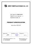
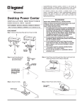
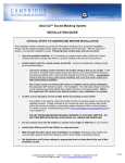
Mounting
Installation
Instructions
& User Manual
Surface Mount
ZONEMASTER PRO
AC Panel Transient Voltage Surge Suppressors
Flush Mount
The Wiremold Company
In US:
60 Woodlawn Street, West Hartford, CT 06110
800-621-0049 FAX 860-232-2062
Outside U.S.: 860-232-6251
In Canada:
850 Gartshore Street, Fergus, Ontario N1M 2W8
(519) 834-4332 FAX (519) 843-5980
801722 Rev A 7/18/08
OPERATION
CONGRATULATIONS! YOU HAVE JUST PURCHASED
THE BEST SURGE PROTECTION IN THE INDUSTRY!
Adhering to these instructions guarantees maximum performance of this protection
device.
INTRODUCTION
The ZoneMaster PRO Series Surge Protection System requires little or no operator
intervention after installation. The units are provided with a multi-mode surge monitor
that provides fault status (audible and visual) and a surge counter that counts how many
transients the unit has suppressed.
Normally the counter displays the number of surges counted. In the event of a module
failure, the display changes to MODULE FAILURE and an audible alarm will sound.
See page 5 for trouble shooting/repair.
This document explains how to install the TVSS ZoneMaster PRO AC Panel Surge
Protection Devices.
STATUS INDICATORS
INSTALLATION INSTRUCTIONS
Warning: Terminals marked L1, L2, L3, N, GND (where relevant) must be connected
respectively to phase(s) neutral and ground. Failure to comply may result in danger or
damage. See corresponding diagrams for proper connections.
The TVSS ZoneMaster PRO units have comprehensive, continuous
visual status monitoring present on each module.
INSTALLATION DESCRIPTION
Status
Indicated
Reduced
(Standby)
Protection
No
Protection
No Power to
Protector
High N-G
Voltage*
TVSS ZoneMaster PRO units are connected in parallel (“shunt”) across the supply
to be protected. The connecting cable does not carry the supply current, only the current
associated with suppressing the transient overvoltage.
Full
Protection
Present
LED
Indicator
Green
LED Lit
Red
LED Lit
Red
LED Lit
Green
LED Out
Red & Green
LED Lit
MOUNTING
The units should be mounted as close as possible to the panel to be protected. See (page
3) on Connecting Lead lengths. Conduit, preferably metallic, is to be installed from the
suppressor to the panel. Determine a location where the connection wire will be installed
and then drill suitable hole in the ZoneMaster PRO.
Power/Protection
Indicator
REMOTE INDICATORS
INCORRECT INSTALLATION WILL IMPAIR THE
EFFECTIVENESS OF THE AC PANEL PROTECTORS.
A remote indication of the reduced protection state is available as a normally open or
normally closed dry contact “Form C”. Rated maximum 1A at 30Vdc resistive and
maximum 0.3A at 125Vac general use. Suitable for connection of AVLV2 18AWG to
20AWG copper wire. Recommended tightening torque: 7 in - lbs.
Routing of these wires should be separate from the power with a minimum of spacing of two inches.
*WARNING:
OF HIGH NEUTRAL TO GROUND VOLTAGE
On certain models, if both Red and Green lights are on, consult a qualified electrical
contractor to check the integrity of the building wiring.
2
7
SETTING SURGE MONITOR MODES OF OPERATION
CONNECTING LEADS
The following is displayed upon power-up and when in monitor mode. To change
monitor options, push the mode button. This will step through the different program
modes. To reset the surge count, hold down both the mode and select buttons for about
5 seconds. The count will be set to zero.
Connect the suppressor as shown in the installation diagram. Connect the terminals
within the suppressor to the load side of 60A breakers or fuses within the panel. See
specific connection diagrams for more details and markings on unit if provided.
M
S
o
n
i
t
o
r
u
r
g
e
C
o
u
M
o
d
e
n
t
=
0
RECOMMENDED WIRE GAUGE - STRANDED COPPER
0
0
0
0
PROGRAM MODE - ALARM
P
A
r
o
g
r
a
m
M
l
a
r
m
=
O N
o
d
Minimum of 8 AWG
Maximum of 4 AWG ( for ease of dressing)
Torque Rating: 35 - 50 in - lbs.
LENGTH OF CONNECTING LEADS
e
ON:
The surge monitor will detect the module status and display “Module Failure”
if a module fails.
OFF: The surge monitor does not give a module status and the audio option is
disabled.
WARNING: If remote monitoring from a different source is desired, the alarm option
must be set to OFF and the connector on the surge monitor disconnected. Failure to do
so will cause damage to the surge monitor and possibly to the connected monitoring
equipment.
The longer the connecting leads between the ZoneMaster PRO and power panel, the
higher the residual transient voltage.
RECOMMENDED MAXIMUM:
500mm (19”)
IDEALLY:
250mm (10”)
Each 250mm increase in cable length increases clamping voltage by 25V per 1000A
surge current discharged.
• BIND THE PHASE NEUTRAL AND GROUND CONDUCTORS
TIGHTLY, OVER THE ENTIRE RUN FROM THE SUPPRESSOR
TO THE SERVICE PANEL.
• ALWAYS USE THE SHORTEST LENGTH OF CONNECTING
CABLE POSSIBLE.
PROGRAM MODE – AUDIO
P
A
r
o
g
r
a
u
d
i
o
=
m
O
M
o
d
e
CONNECTION
N
ON:
fails
The alarm will sound for about 2 seconds if a surge is detected. If a module
the alarm will sound continuously until either the mode or select button is
pushed.
OFF: No alarm is sounded and only the display will indicate that a module has failed
or a surge was detected.
(Typical 8/20µs impulse)
P
S
o
g
r
a
m
e
n
s
i
t
i
v
M
o
d
e
i
t
y
=
Display will read - *200A or *500A
*Level at which counter will register a surge count.
2
VERIFY THAT ALL POWER CIRCUITS ARE DE-ENERGIZED AND
LOCKED OUT BEFORE MAKING ELECTRICAL CONNECTIONS.
Before making connections to the unit, verify that the ZoneMaster PRO service rating is
appropriate for connection to the intended electrical service. Each ZoneMaster PRO has
terminal lugs that are marked L1, L2, L3, N and G where appropriate. See figures 1, 2 or
3, depending on the model of the ZoneMaster PRO.
PROGRAM MODE – SENSITIVITY
r
WARNING
0
0
A
WARNING — Connect the high-leg or wild-leg to terminal L2 when installing the unit on a high-leg delta electrical service. Mis-installation will cause
the suppressor to fail upon power-up.
Press mode again to return to monitor mode.
6
3
120/208V Three Phase 4W WYE
120/240V Three Phase 4W DELTA (HL = L2)
277/480V Three Phase 4W WYE
240/415V Three Phase 4W WYE
220/380V Three Phase 4W WYE
For side mounting follow these schematics:
240V Three Phase 3W DELTA
480V Three Phase 3W DELTA
60A
L3
L2
L1
N
N
60A
L1
L2
L3
L1
L2
L3
G
G
Figure 3
TROUBLESHOOTING/REPAIR
WARNING -- ONLY QUALIFIED PERSONNEL SHOULD PERFORM MAINTENANCE ON THIS UNIT. HAZARDOUS VOLTAGES ARE PRESENT INSIDE THE
UNIT DURING NORMAL OPERATIONS. ELECTRICAL SAFETY PRECAUTIONS
MUST BE FOLLOWED WHEN SERVICING THIS UNIT. TO PREVENT RISK OF
ELECTRICAL SHOCK, TURN OFF AND LOCK OUT ALL POWER SOURCES
TO THE UNIT BEFORE SERVICING.
Figure 1
120/240V Split Phase 3W
L2
L1
60A
N
Remove the cover and determine which module has failed by reviewing the LED status
indication window (see page 7 ‘Status Indicators’) then disconnect the power. Next, disconnect the remote monitoring plug located on top of the module. Then use a socket wrench or
nutdriver to remove the ¼” nuts that hold the module in place. Replace module with same
type and color code. Replace ¼” nuts and tighten securely. DO NOT OVERTIGHTEN. Insert remote monitoring plug. Install cover, restore power and check for normal operation.
N
L1
L2
EXTERNAL DISCONNET UNIT
G
Figure 2
4
Located on the cover is the LED status indication of each module (see page 7 ‘Status Indicators’). Determine which module has failed then disconnect power and remove the cover.
Disconnect remote monitor plug. Use a socket wrench or nutdriver to remove the ¼” nuts
that hold the module in place. Replace module with same type and color code. Replace ¼”
nuts and tighten securely. DO NOT OVERTIGHTEN. Insert remote monitoring plug.
Install cover and restore power and check for normal operation.
5
SETTING SURGE MONITOR MODES OF OPERATION
CONNECTING LEADS
The following is displayed upon power-up and when in monitor mode. To change
monitor options, push the mode button. This will step through the different program
modes. To reset the surge count, hold down both the mode and select buttons for about
5 seconds. The count will be set to zero.
Connect the suppressor as shown in the installation diagram. Connect the terminals
within the suppressor to the load side of 60A breakers or fuses within the panel. See
specific connection diagrams for more details and markings on unit if provided.
M
S
o
n
i
t
o
r
u
r
g
e
C
o
u
M
o
d
e
n
t
=
0
RECOMMENDED WIRE GAUGE - STRANDED COPPER
0
0
0
0
PROGRAM MODE - ALARM
P
A
r
o
g
r
a
m
M
l
a
r
m
=
O N
o
d
Minimum of 8 AWG
Maximum of 4 AWG ( for ease of dressing)
Torque Rating: 35 - 50 in - lbs.
LENGTH OF CONNECTING LEADS
e
ON:
The surge monitor will detect the module status and display “Module Failure”
if a module fails.
OFF: The surge monitor does not give a module status and the audio option is
disabled.
WARNING: If remote monitoring from a different source is desired, the alarm option
must be set to OFF and the connector on the surge monitor disconnected. Failure to do
so will cause damage to the surge monitor and possibly to the connected monitoring
equipment.
The longer the connecting leads between the ZoneMaster PRO and power panel, the
higher the residual transient voltage.
RECOMMENDED MAXIMUM:
500mm (19”)
IDEALLY:
250mm (10”)
Each 250mm increase in cable length increases clamping voltage by 25V per 1000A
surge current discharged.
• BIND THE PHASE NEUTRAL AND GROUND CONDUCTORS
TIGHTLY, OVER THE ENTIRE RUN FROM THE SUPPRESSOR
TO THE SERVICE PANEL.
• ALWAYS USE THE SHORTEST LENGTH OF CONNECTING
CABLE POSSIBLE.
PROGRAM MODE – AUDIO
P
A
r
o
g
r
a
u
d
i
o
=
m
O
M
o
d
e
CONNECTION
N
ON:
fails
The alarm will sound for about 2 seconds if a surge is detected. If a module
the alarm will sound continuously until either the mode or select button is
pushed.
OFF: No alarm is sounded and only the display will indicate that a module has failed
or a surge was detected.
(Typical 8/20µs impulse)
P
S
o
g
r
a
m
e
n
s
i
t
i
v
M
o
d
e
i
t
y
=
Display will read - *200A or *500A
*Level at which counter will register a surge count.
2
VERIFY THAT ALL POWER CIRCUITS ARE DE-ENERGIZED AND
LOCKED OUT BEFORE MAKING ELECTRICAL CONNECTIONS.
Before making connections to the unit, verify that the ZoneMaster PRO service rating is
appropriate for connection to the intended electrical service. Each ZoneMaster PRO has
terminal lugs that are marked L1, L2, L3, N and G where appropriate. See figures 1, 2 or
3, depending on the model of the ZoneMaster PRO.
PROGRAM MODE – SENSITIVITY
r
WARNING
0
0
A
WARNING — Connect the high-leg or wild-leg to terminal L2 when installing the unit on a high-leg delta electrical service. Mis-installation will cause
the suppressor to fail upon power-up.
Press mode again to return to monitor mode.
6
3
OPERATION
CONGRATULATIONS! YOU HAVE JUST PURCHASED
THE BEST SURGE PROTECTION IN THE INDUSTRY!
Adhering to these instructions guarantees maximum performance of this protection
device.
INTRODUCTION
The ZoneMaster PRO Series Surge Protection System requires little or no operator
intervention after installation. The units are provided with a multi-mode surge monitor
that provides fault status (audible and visual) and a surge counter that counts how many
transients the unit has suppressed.
Normally the counter displays the number of surges counted. In the event of a module
failure, the display changes to MODULE FAILURE and an audible alarm will sound.
See page 5 for trouble shooting/repair.
This document explains how to install the TVSS ZoneMaster PRO AC Panel Surge
Protection Devices.
STATUS INDICATORS
INSTALLATION INSTRUCTIONS
Warning: Terminals marked L1, L2, L3, N, GND (where relevant) must be connected
respectively to phase(s) neutral and ground. Failure to comply may result in danger or
damage. See corresponding diagrams for proper connections.
The TVSS ZoneMaster PRO units have comprehensive, continuous
visual status monitoring present on each module.
INSTALLATION DESCRIPTION
Status
Indicated
Reduced
(Standby)
Protection
No
Protection
No Power to
Protector
High N-G
Voltage*
TVSS ZoneMaster PRO units are connected in parallel (“shunt”) across the supply
to be protected. The connecting cable does not carry the supply current, only the current
associated with suppressing the transient overvoltage.
Full
Protection
Present
LED
Indicator
Green
LED Lit
Red
LED Lit
Red
LED Lit
Green
LED Out
Red & Green
LED Lit
MOUNTING
The units should be mounted as close as possible to the panel to be protected. See (page
3) on Connecting Lead lengths. Conduit, preferably metallic, is to be installed from the
suppressor to the panel. Determine a location where the connection wire will be installed
and then drill suitable hole in the ZoneMaster PRO.
Power/Protection
Indicator
REMOTE INDICATORS
INCORRECT INSTALLATION WILL IMPAIR THE
EFFECTIVENESS OF THE AC PANEL PROTECTORS.
A remote indication of the reduced protection state is available as a normally open or
normally closed dry contact “Form C”. Rated maximum 1A at 30Vdc resistive and
maximum 0.3A at 125Vac general use. Suitable for connection of AVLV2 18AWG to
20AWG copper wire. Recommended tightening torque: 7 in - lbs.
Routing of these wires should be separate from the power with a minimum of spacing of two inches.
*WARNING:
OF HIGH NEUTRAL TO GROUND VOLTAGE
On certain models, if both Red and Green lights are on, consult a qualified electrical
contractor to check the integrity of the building wiring.
2
7
Mounting
Installation
Instructions
& User Manual
Surface Mount
ZONEMASTER PRO
AC Panel Transient Voltage Surge Suppressors
Flush Mount
The Wiremold Company
In US:
60 Woodlawn Street, West Hartford, CT 06110
800-621-0049 FAX 860-232-2062
Outside U.S.: 860-232-6251
In Canada:
850 Gartshore Street, Fergus, Ontario N1M 2W8
(519) 834-4332 FAX (519) 843-5980
801722 Rev A 7/18/08