1
Sep. 19, 2002
US 2002/0130181 A1
codes) may nonetheless be provided in the user manual to
end connector 122 is plugged into the scanner 155, the
allow the user to con?gure the peripheral as desired such as
scanner 155 cannot be oriented to scan a label located
to speci?c user optional settings. Alternately, the program
immediately adjacent the ?rst end connector 122.
ming label may be positioned on the host computer or
terminal. Such a location may be less desirable since dif
ferent scanners may be plugged into the same host, possibly
desirable to locate the label 135 near the ?rst end connector
requiring different programming labels. Alternately, the pro
gram sWitch label may be positioned on the host as shoWn
by the label 342 on the host 340 of FIG. 14. The user Would
then scan the label 342 to sWitch to programming mode and
then scan the programming label 335 on the cable 320.
[0059] Nonetheless, in certain applications it may be
122. If the connector cable 120 is relatively long, for
example 50 feet (15 meters), the label may be preferably
positioned about 2 feet (60 cm) from the ?rst end connector
122. Such a position is close enough to be easily located but
far enough to alloW convenient access. Such a location is
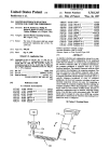
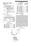
illustrated in FIG. 14 Where the bar code label 335 is located
[0052] Con?guration on the basis of the encoded data
instructions obtained by reading the label or bar code 335
may be accomplished by a suitable internal con?guration
routine. For example, the routine may con?gure by Way of
ment and the cable connector data reader con?guration
selecting proper internal sWitch settings or by selecting and
running a given protocol program. The data reader prefer
embodiment may be used separately to con?gure the periph
eral, the embodiments may be combined together to provide
on the cable 320 at a convenient distance from scanner 310.
[0060] Though the cable connector con?guration embodi
ably stores its con?guration parameters in a non-volatile
a comprehensive and readily implemented con?guration
programmable memory such as EEPROM. These param
eters may be set by manual programming or reset by the
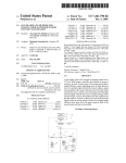
procedure. By Way of example, FIG. 15 illustrates a periph
commands resulting in the setting (or resetting) of the
eral shoWn as a laser scanner 410 is equipped With a
multi-interface architecture Which alloWs any one of many
different types of host interfaces (such as a data terminal
440, a ?xed scanner or other point of sale unit 450, or a
EEPROM-stored parameters.
handheld key entry unit 460) to be selected for a particular
con?guration routine. The instructions from the label may
cause the softWare in the data reader to execute a series of
scanner. A cable 420 is selected corresponding to the par
[0053] Con?guration selection or parameters change or set
a particular function for the peripheral. Possible con?gura
tion selections or parameters may include, by Way of
example for a handheld scanner:
[0054] interface identi?cation (for a laser scanner,
may include Undecoded, IBM 4683, OCIA, RS-232,
Wand Emulation, etc.);
[0055]
communication parameters such as baud rate
ticular scanner 410 and the desired host interface (440, 450,
460) pair. In practice, the user is supplied With a plurality of
speci?c connector cables Which correspond to the possible
scanner/host pairs Which the customer may have.
[0061] When plugged into the scanner, the cable 420 itself
selects a certain con?guration scheme in the scanner 410.
The cable 420 may also con?gure the host interface. The
cable 420 may be equipped With physical connector ele
(2400 baud, 9600 baud etc.); data format settings
(parity, stop bits, data bits), hardWare handshaking
(CTS/RTS), softWare handshaking (Xon,Xoff), inter
physically plugged into the host. Once plugged into the
character delay (none, 10 ms, 20 ms etc.), UPC Data
then scans the label on the cable Which completes or
Format (UPA-A, UPC-E, Check Digit, Number Sys
tem Digit);
con?rms scanner/host con?guration.
ments to ensure that only the correct cable may be even
scanner and the host, using the scanner itself, the operator
[0056] system speci?c parameters (pre?xes, suffixes,
symbology identi?ers, etc.);
[0062] Besides the bar code label, there are other types of
labels or tags containing information Which may be obtained
by a reader device. One such label or tag is an RFID tag
[0057] reading restrictions, the instructions might
(radio frequency identi?cation tag). The RFID tag is nor
mally passive, but When activated or prompted by a signal
restrict the set of codes options that the decoder may
have to handle; by restricting the reading options, the
operation speed of the “autodiscrimination” algo
rithm (the means by Which the decoder ?gures out
Which code it is seeing) may be increased as com
pared to requiring the algorithm to consider all code
types.
[0058]
The preferred actual location on the cable for the
from a interrogator, the RFID tag emits a signal With its
information to a receiving device. In one alternative embodi
ment, the cable 320 may include a label 336 comprising an
RFID tag instead of a bar code. The scanner 310 may
comprise an RFID tag interrogator/receiver (either exclu
sively or in combination With a bar code scanning mecha
nism) Which prompts the RFID tag 336 for its data and
receives the data. The data is then used to set internal
encoded label Will depend upon the particular application.
con?guration, function or the like. The programming RFID
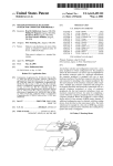
Referring to FIG. 5 for example, the label 135 is located
adjacent the second end connector. An alternate location is
tag process may be initiated for example by actuating the
directly on the second end connector 124 as shoWn by
symbol label 133 on end connector 124. If the second end
connector 124 is too small to practically accommodate the
label 133 or if the connection location to the data terminal
programming sWitch 312 on the device 310. Alternately,
programming may be automatically initiated upon poWer up
or poWer doWn of the device 310. In the poWer up example,
140 provides inconvenient access, the label 135 may pref
When the device is poWered up, the programming frequency
signal Would be emitted and upon receipt the RFID tag
Would emit its signal transmitting programming data to the
erably be located up the cable connector 120 at a suitable
distance from the second end connector 124. In general, it is
impractical to locate the label 135 on the ?rst end connector
device. Such a system Would not require the user to perform
any act except plug in the correct cable and turn on the data
reader and the data reader itself Would obtain the proper
122 or immediately adjacent thereto because When the ?rst
con?guration information (for example) from the RFID tag