1
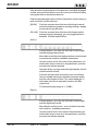
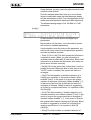
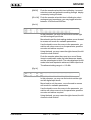
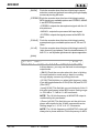
SDC2000 User Manual Manufactured by Italy File name: CAPITOLI_EN.P65 Version: 1.0 Date: 12/04/2005 Revision History Date Version 12/04/05 1.0 Reason First Version Editor J. Berti SDC2000 - User Manual Version 1.0 © Copyright 2005 R.V.R. Elettronica SpA Via del Fonditore 2/2c - 40138 - Bologna (Italia) Telefono: +39 051 6010506 Fax: +39 051 6011104 Email: [email protected] Web: www.rvr.it All rights reserved Printed and bound in Italy. No part of this manual may be reproduced, memorized or transmitted in any form or by any means, electronic or mechanic, including photocopying, recording or by any information storage and retrieval system, without written permission of the copyright owner. SDC2000 Table of Contents 1. 2. 3. 3.1 3.1.1 3.1.2 3.2 3.2.1 3.2.2 4. 4.1 5. 5.1 5.2 5.3 5.3.1 5.3.2 5.3.3 5.3.4 5.3.5 5.3.6 5.3.7 5.3.8 6. 6.1 6.2 6.2.1 6.2.2 6.2.3 6.3 6.4 6.5 6.5.1 6.5.1.1 6.5.1.2 6.5.1.3 6.5.1.4 6.5.1.5 6.5.1.6 Preliminary Instructions Warranty First Aid Treatment of electrical shocks If the victim is not responsive If victim is responsive Treatment of electrical Burns Extensive burned and broken skin Less severe burns Unpacking General Description External Description Front Panel Rear Panel Connectors Pinout RS 232 Remote Left (MONO) / Right (MPX Bal) AES/EBU TOS-LINK Digital Output Keyboard Remote GPS Quick Reference - Installation and use Preparation Installation Digital Connection Analogue Connection SDC2000/SFN Connection Use Encoder Use Normal Operation Main Menu 1 1 1 1 1 2 2 2 2 3 3 5 5 5 6 6 6 6 6 7 7 7 7 8 8 8 9 9 9 10 10 10 12 [vers] [audio] [rds] [system] [clock] [GPS] (only available where option /SFN is installed) 13 13 25 30 31 32 User Manual Rev. 1.0 - 12/04/05 i SDC2000 7. 7.1 7.2 7.3 8. 8.1 8.2 ii RDS Functions Introduction Description of RDS RDS Software Technical Specifications Mechanical Specifications Electric Specifications Rev. 1.0 - 12/04/05 34 34 34 36 38 38 38 User Manual SDC2000 1. Preliminary Instructions To claim your rights under this warranty, you shold follow this procedure: This manual is written as a general guide for those having previous knowledge and experience with this kind of equipment, well conscious of the risks connected with the operation of electrical equipment. It is not intended to contain a complete statement of all safety rules which should be observed by personnel in using this or other electronic equipment. The installation, use and maintenance of this piece of equipment involve risks both for the personnel performing them and for the device itself, that shall be used only by trained personnel. 1 Dealers and Distributors are supplied with all the information about problems that may occur and usually they can repair the unit quicker than what the manufacturer could do. Very often installing errors are discovered by dealers. 2 If your dealer cannot help you, contact R.V.R. Elettronica and explain the problem. If it is decided to return the unit to the factory, R.V.R. Elettronica will mail you a regular authorization with all the necessary instructions to send back the goods; 3 When you receive the authorization, you can return the unit. Pack it carefully for the shipment, preferably using the original packing and seal the package perfectly. The customer always assumes the risks of loss (i.e., R.V.R. is never responsible for damage or loss), until the package reaches R.V.R. premises. For this reason, we suggest you to insure the goods for the whole value. Shipment must be effected C.I.F. (PREPAID) to the address specified by R.V.R.’s service manager on the authorization R.V.R. Elettronica SpA doesn’t assume responsibility for injury or damage resulting from improper procedures or practices by untrained/unqualified personnel in the handling of this unit. Please observe all local codes and fire protection standards in the operations of this unit. WARNING: always disconnect power before opening covers or removing any part of this unit. Please observe all local codes and fire protection standards in the operations of this unit. WARNING: this device can irradiate radio frequency waves, and if it’s not installed following the instructions contained in the manual and local regulations it could generate interferences in radio communications. DO NOT RETURN UNITS WITHOUT OUR AUTHORIZATION AS THEY WILL BE REFUSED 4 This is a "CLASS A" equipment. In a residential place this equipment can cause hash. In this case can be requested to user to take the necessary measures. R.V.R. Elettronica SpA reserves the right to modify the design and/or the technical specifications of the product and this manual without notice. 2. R.V.R. Elettronica SpA Via del Fonditore, 2/2c 40138 BOLOGNA ITALY Tel. +39 051 6010506 Any product of R.V.R. Elettronica is covered by a 24 (twenty-four) month warranty. 3. R.V.R. Elettronica SpA extends to the original end-user purchaser all manufacturers warranties which are transferrable and all claims are to be made directly to R.V.R. per indicated procedures. 1 Re-shipment of the unit to R.V.R. for repair purposes; 2 Any unauthorized repair/modification; 3 Incidental/consequential damages as a result of any defect; 4 Nominal non-incidental defects; 5 Re-shipment costs or insurance of the unit or replacement units/parts. First Aid The personnel employed in the installation, use and maintenance of the device, shall be familiar with theory and practice of first aid. 3.1 Warranty shall not include: Be sure to enclose a written technical report where mention all the problems found and a copy of your original invoice establishing the starting date of the warranty. Replacement and warranty parts may be ordered from the following address. Be sure to include the equipment model and serial number as well as part description and part number. Warranty For components like tubes for power amplifiers, the original manufacturer’s warranty applies. Contact the dealer or distributor where you purchased the unit. Describe the problem and, so that a possible easy solution can be detected. 3.1.1 Treatment of electrical shocks If the victim is not responsive Follow the A-B-C's of basic life support. • Place victim flat on his backon a hard surface. • Open airway: lift up neck, push forehead back (Figure 1). Any damage to the goods must be reported to the carrier in writing on the shipment receipt. Any discrepancy or damage discovered subsequent to delivery, shall be reported to R.V.R. Elettronica within 5 (five) days from delivery date. Figure 1 User Manual Rev. 1.0 - 12/04/05 1 / 40 SDC2000 • clear out mouth if necessary and observe for breathing • if not breathing, begin artificial breathing (Figura 2): tilt head, pinch nostrils, make airtight seal, four quick full breaths. Remember mouth to mouth resuscitation must be commenced as soon as possible. adhered particles of clothing, or apply any salve or ointment. • Treat victim for shock as required. • Arrange transportation to a hospital as quickly as possible. • If arms or legs are affected keep them elevated. If medical help will not be available within an hour and the victim is conscious and not vomiting, give him a weak solution of salt and soda: 1 level teaspoonful of salt and 1/ 2 level teaspoonful of baking soda to each quart of water (neither hot or cold). Allow victim to sip slowly about 4 ounces (half a glass) over a period of 15 minutes. Figura 2 Discontinue fluid if vomiting occurs. • Check carotid pulse (Figura 3); if pulse is absent, begin artificial circulation (Figura 4) depressing sternum (Figura 5). DO NOT give alcohol. 3.2.2 Figure 3 Figure 4 Less severe burns • Apply cool (not ice cold) compresses using the cleansed available cloth article. • Do not break blisters, remove tissue, remove adhered particles of clothing, or apply salve or ointment. • Apply clean dry dressing if necessary. • Treat victim for shock as required. • Arrange transportation to a hospital as quickly as possible. • If arms or legs are affected keep them elevated. Figure 5 3.1.2 3.2 3.2.1 2 / 40 • In case of only one rescuer, 15 compressions alternated to two breaths. • If there are two rescuers, the rythm shall be of one brath each 5 compressions. • Do not interrupt the rythm of compressions when the second person is giving breath. • Call for medical assistance as soon as possible. If victim is responsive • Keep them warm. • Keep them as quiet as possible. • Loosen their clothing (a reclining position is recommended). • Call for medical help as soon as possible. Treatment of electrical Burns Extensive burned and broken skin • Cover area with clean sheet or cloth. • Do not break blisters, remove tissue, remove Rev. 1.0 - 12/04/05 User Manual SDC2000 4. Unpacking The package contains: • SDC2000 • User Manual • CD -ROM with Software • Mains power cables The following accessories are also available from Your R.V.R. Dealer: 4.1 • /SFN (advanced isofrequency features • Accessories, spare parts and cables General Description The SDC2000 is a high-performance digital stereo encoder. Designed for radiofrequency FM stereo broadcasting, it is housed in a 1HE box for 19" rack mount. The SDC2000 generates an MPX (composite stereo) signal that is processed digitally in its analogue form using the Right and Left analogue inputs, the AES/EBU analogue inputs or the optical input; this ensures: – High signal-to-noise ratio (S/N, higher than 80 dB) and high fidelity of stereophonic signal . – High stereophonic separation throughout the frequency range (higher than 65 dB). This economical device incorporates all technical features offered by more expensive coders without compromising on quality; it combines high DSP-based Digital Stereo performance with an RDS coder. The Integrated RDS coder is capable of processing standard PI, PS, PTY TP, TA, AF, M/S, PIN, RT, EON, TDC and IH signals. User interface consists of a graphic liquid crystal display and a knob (encoder). This interface lets you view all parameters relating to machine operation and adjust settable parameters (e.g.: preemphasis, right and left analogue channel level, etc...). A PS/2 port on the front panel enables keyboard connection to facilitate setting of operating parameters. This high-performance stereo coder uses an internal DSP (Digital Signal Processing) circuit that provides high modulation linearity, high stereo separation and high input level capacity. The SDC2000 can process coded digital input signals using the AES/EBU standard, or using the "Left" and "Right" analogue signals, that are converted into digital format (A/D). User Manual Rev. 1.0 - 12/04/05 3 / 40 SDC2000 The digital input/output section supports S/PDIF, AES/EBU (sampling frequencies from 32 to 96 KHz ) and EIAJ CP340/1201 data format. The top-quality analogue input/output section supports digital system response in terms of high input dynamics, high signal-to-noise ratio and very low distortion. Two buffered MPX outputs, each with independent levels, maintain best stereo separation even when load is as low as 50 Ohm. The machine features an optimised ground distribution system (Audio and chassis ) to avoid ground loops. The SDC2000 design is based on a modular concept: the different functions are performed by modules that are either connected directly (male connector of one module attached to female connector of another module) or through flat cables terminated by connectors. This design facilitates maintenance and module replacement. /SFN option (Specifically designed for isofrequency applications) The SDC2000/SFN enables isofrequency operation (SFN, Single Frequency Networks) throughout the country; in other words, the same transmission frequency can be used for transmitters that have partially overlapping coverage areas. The SDC2000/SFN implements a supplemental technology that uses a delay on all inputs (Left, Right, MPX and AES/ EBU) to provide optimised frequency planning as well as an integrated GPS (that enables 1 ppm synchronisation on pilot frequency and delays). 4 / 40 Rev. 1.0 - 12/04/05 User Manual SDC2000 5. External Description This section describes the components found on the front and rear panel of the SDC2000. 5.1 Front Panel [1] [2] [3] [4] 5.2 DISPLAY ENCODER KEYBOARD ON/OFF Liquid Crystal Display Software control knob and button PS/2 connector for direct connection to PC Keyboard Mains power switch. Switch off equipment without disconnecting mains power. Rear Panel [1] PLUG & A.C. LINE FUSE [2] OUT 10MHz [3] [4] [5] GPS REMOTE IN RF AUX [6] [7] [8] [9] [10] [11] [12] [13] [14] [15] [16] [17] [18] [19] [20] B A LEVEL ADJ A MPX SCA2 LEVEL ADJ SCA2 SCA1 LEVEL ADJ SCA1 RIGHT LEFT AES-EBU TOS-LINK DIGITAL OUTPUT REMOTE RS232 User Manual 110-230V 50-60Hz mains power plug and fuse block. Use a small screwdriver to extract block and change fuses. Synchronism signal output connector for external devices,, BNC type (opt. /SFN) DB9 connector (opt. /MPX DIGITALE - SFN ) GPS antenna input connector, TNC type (opt. /SFN) MPX - RDS - 19KHz analogue output auxiliary connector AUX, BNC type MPX+RDS analogue output connector B, BNC type Trimmer for A output level adjustment MPX+RDS analogue output connector A, BNC type MPX analogue input connector, BNC type Trimmer for SCA2 input level adjustment SCA2 analogue input connector, BNC type Trimmer for SCA1 input level adjustment SCA1 analogue input connector, BNC type Right audio channel analogue input connector, female XLR type Left audio channel analogue input connector, female XLR type AES-EBU digital audio input connector, XLR type Fibre-optics digital audio input connector Unbalanced S/PDIF digital audio output connector, RCA type DB9 connector for interface to remote devices DB9 connector for interface to remote devices and factory programming Rev. 1.0 - 12/04/05 5 / 40 SDC2000 5.3 Connectors Pinout 5.3.1 RS 232 Type: Female DB9 1 6 1 2 3 4 5 6 7 8 9 NC TX_D RX_D NC GND +12V NC CTS NC Note: Normallly, the SDC2000 is configured as DCE (Data Communication Equipment) for serial communication. 5.3.2 Remote Type: DB9 male 1 6 5.3.3 1 2 3 4 5 6 7 8 9 GND RDS MS RDS TA RDS TP +3V3 Reserved Reserved Reserved Reserved Left (MONO) / Right (MPX Bal) Type: XLR female 2 1 3 5.3.4 1 2 3 GND In phase (+) Return (-) AES/EBU Type: XLR female 2 3 6 / 40 1 1 2 3 GND In phase (+) Return (-) Rev. 1.0 - 12/04/05 User Manual SDC2000 5.3.5 TOS-LINK Type: TOS-LINK female 5.3.6 Digital Output Type: RCA female 1 2 3 5.3.7 GND In phase (+) Return (-) Keyboard Type:PS/2 female 6 1 2 3 4 5 6 5 4 3 2 1 5.3.8 Data NC GND +5V Clock NC Remote GPS Type: DB9 female 1 6 User Manual (MPX Digitale Vers.) 1 NC 2 NC 3 Reserved 4 NC 5 GND 6 NC 7 NC 8 INPUT 1PPS 9 GND (/SFN Vers.) 1 Reserved 2 Reserved 3 OUT.GPS BOARD OK 4 Reserved 5 GND 6 Reserved 7 Reserved 8 OUTPUT 1PPS 9 GND Rev. 1.0 - 12/04/05 7 / 40 SDC2000 6. Quick Reference - Installation and use This section contains the necessary information for installing and using the machine. In the event that any aspects are not completely clear, for example when using the machine for the first time, we recommend you carefully read the entire description contained in this manual. 6.1 Preparation Unpack the SDC2000 and before doing any operation, be sure it has not been damaged during transport. In particular check that all connectors are in perfect condition. Check that the voltage selected coincide with mains voltage. The protection fuses can be accessed from the outside on the rear panel. Extract the fuse carrier with a screwdriver to check its integrity or for replacement, if necessary. The voltage selection block accommodates two line fuses. The following type of fuse is used: 2x A.C. LINE FUSE 6.2 315mA 250V (5X20) Installation The SDC2000 accepts AES/EBU digital inputs or Left and Right analogue inputs converted into digital format (A/D). The SDC2000 generates the MPX stereo audio signal directly in digital form, starting from the Left and Right digital channels; this ensures: – Clean, high-fidelity stereophonic signal – High stereophonic separation throughout the band In SDC2000, the RDS signal is generated by the DSP (Digital Signal Processor) and digitally added to the stereophonic audio signal; in the analogue version, the RDS signal (modulated subcarrier) is generated by an external equipment and mixed with the MPX signal. The MPX + RDS signal is converted into an analogue signal (D/A) and used in the direct modulation of the RF carrier through an analogue VCO/PLL, that offers excellent S/N levels and stability and avoids spurious output, which is typically associated with current DDS modulation schemes. 8 / 40 Rev. 1.0 - 12/04/05 User Manual SDC2000 6.2.1 Digital Connection • Ensure that the SDC2000 Stereo Decoder is switched off. • Connect the digital output connector of the mixer, or of the last receiver, to the digital input connector of the SDC2000. The SDC2000 has an XLR connector and an optical TOS-Link input connector. • If you use the XLR connector, a 110 Ohm shielded cable for digital audio AES/ EBU is recommended. Observe the XLR connector pinout shown in chapter 6. If you opt for the TOS-Link connector, use a fibre-optics cable. • The SDC2000 output connection uses the coaxial digital audio output S/PDIF (RCA). A 75 Ohm shielded coaxial cable is recommended for this connector. • Connect the mains power cable to the jack on the rear of the machine. NOTE:The equipment must be properly connected to ground. Correct ground connection is a prerequisite to ensure safe operation and performance. 6.2.2 Analogue Connection • Ensure that the SDC2000 Stereo Decoder is switched off. • Connect the analogue output connectors of the mixer or of the last receiver to the Right and Left input connectors. The SDC2000 is balanced and uses XLR connectors. Alternatively, you may connect the mixer output or the last receiver output to the MPX BNC connector, depending on which configuration best suits the specific needs of your application. • Observe the pinouts of the XLR connectors shown in chapter 6. The SDC2000 uses SCA inputs; please refer to chapter 7 for the specifications of these inputs. • Connect the mains power cable to the jack on the rear of the machine. NOTE: The equipment must be properly connected to ground. Correct ground connection is a prerequisite to ensure safe operation and performance. 6.2.3 SDC2000/SFN Connection • Besides the digital or analogue connections discussed above, some additional connections are required to ensure correct isofrequency operation. • Connect the RF BNC input to a reference generator output controlled by a GPS clock. • Connect the remote cable to a telemetry system. • Connect the 10 MHz BNC output to any other equipments within your system that need synchronising. User Manual Rev. 1.0 - 12/04/05 9 / 40 SDC2000 6.3 Use This section contains the necessary information for installing and using the machine. In the event that any aspects are not completely clear, for example when using the machine for the first time, we recommend you carefully read the entire description contained in this manual. 6.4 Encoder Use The encoder enables user and software interaction. Turn the encoder counterclockwise to move the cursor downwards, to decrease the value of a parameter or to choose an element from a list of possibilities Turn the encoder clockwise to move the cursor upwards, to increase the value of a parameter or to choose an element from a list of possibilities Push the button once to enter in the desired menu, to enter in modification mode or to confirm a choice Figure 5-1 The operations supported by the encoder are: • rotation: moves cursor left or right on the display; increases or decreases selected parameters (turn left to decrease, turn right to increase) and selects an item from a list of options. • pushing: push the button once when the cursor is on the name of a menu to access that menu; push the button when the cursor is on a parameter to enter edit mode (cursor begins to blink); after changing a parameter, push the button to save the new setting. After changing a parameter, the cursor will keep blinkng until setting is confirmed; afterwards, it stops blinking and stays on the selected parameter. 6.5 Normal Operation Switch on the SDC2000 using the switch on the front panel. Upon power-on, DSP initialising information is displayed for a few seconds. On completion, the LCD shows the default screen that provides a graphic display of the instantaneous levels of MPX outputs and pilot tone: 10 / 40 Rev. 1.0 - 12/04/05 User Manual SDC2000 MPX output and Pilot level screen Use the encoder to move within the menu and browse the different SDC2000 input level screens. Turn the knob clockwise to call up the following screens: 1. Right and Left Analogue input levels screen 2. Right and Left Digital input levels screen 3. SCA levels screen 4. SCA levels screen Or, on versions with MPX Digital input: SCA3 and MPX Input levels screen (only on MPX Digital input versions) 5. Main Menu (may only be accessed after entering a valid User Password or when no User Password has been set) User Manual Rev. 1.0 - 12/04/05 11 / 40 SDC2000 If the encoder is pushed when in this menu, field [BACK] begins to blink and you will be able to move the cursor from field to field by turning the knob in the desired direction. Push the encoder again when a field is selected to confirm that you wish to edit the current selection. Please read the next paragraph for menu edit instructions. [BACK] Push the encoder when this item is blinking to cancel selection mode and go back to scrolling through display screens by turning the knob. [vers] Push the encoder when this item is blinking to view information about the SDC2000 software release. Displayed information may vary depending on the firmware installed. [audio] Push the encoder when this item is blinking to access a set of submenus where you can edit all parameters of the audio section. [rds] Push the encoder when this item is blinking to access a set of submenus where you can edit all parameters of the audio section. [system] Push the encoder when this item is blinking to access a set of submenus where you can edit certain system parameters, such as password, selected language, etc... . [clock] Push the encoder when this item is blinking to change the SDC2000 internal clock setting. [GPS] Push the encoder when this item is blinking to open a window where you can check GPS operation (NOTE: this field is only present when the GPS has been enabled by the manufacturer). The field is only available when option /SFN is installed. 6. I.T.U. and MPX output levels screen Keep turning the encoder clockwise and you will go back to the default screen, that shows MPX output and pilot tone levels. 6.5.1 Main Menu From this menu, you can set all operating parameters of the machine. Please note that you must enter the correct password (where it has been set) before you can access this menu. When the password is acknowledged as correct, you can edit the parameters held in this menu. 12 / 40 Rev. 1.0 - 12/04/05 User Manual SDC2000 Main Menu (may only be accessed after entering a valid User Password or when no User Password has been set) When the screen shown above is displayed, push the encoder to scroll through listed items and push it again to select the desired item. The menus shown below are listed in the order they are accessed when turning the knob clockwise. 6.5.1.1 [vers] Release information window This window shows information on the SDC2000 software release. Displayed information may vary depending on the firmware installed. Push the knob again to go back to the previous menu. 6.5.1.2 [audio] Audio Section Submenus Pushing the encoder when this item is blinking gives access to a set of submenus where you can edit certain parameters of the audio section. If the encoder is pushed when in this submenu, field [BACK] begins to blink and you will be able to move the cursor from field to field by turning the knob in the desired direction. Push the encoder again when a field is selected to confirm that you wish to edit the current selection. Please read the next paragraph for menu edit instructions. [BACK] User Manual Push the encoder when this item is blinking to cancel selection mode and go back to scrolling through display screens by turning the knob. [Input] (version with PASS-THROUGH MPX) Rev. 1.0 - 12/04/05 13 / 40 SDC2000 If the encoder is pushed when in this submenu, field [BACK] begins to blink and you will be able to move the cursor from field to field by turning the knob in the desired direction. Push the encoder again when a field is selected to confirm that you wish to edit the current selection. [BACK] Push the encoder when this item is blinking to cancel selection mode and go back to scrolling through display screens by turning the knob. [Ri=10K] Push the encoder when this item is blinking to select analogue input impedance; you may toggle selection between 10 kOhm and 600Ohm. [Anl-lv] In this submenu, you may use the knob to set the right and left analogue input levels. Move back to exit the clock setting window; move forward to access edit mode for available parameters. Use the knob to move the cursor to the parameter you wish to edit; when cursor is on the parameter, push the encoder and edit as required. Using the knob, you may cause the right channel, the left channel or both to blink. Push the encoder when the cursor is on one of these items to enable edit mode; the label becomes steady and the value begins to blink. The value displayed in edit mode is the level required to achieve a 0 dBu output level. The allowed setting range is +/-12 dBu. [Dgt-lv] In this submenu, you may use the knob to set the right and left digital input levels. Move back to exit the menu; move forward to access edit mode for available parameters. Use the knob to move the cursor to the parameter you wish to edit; when cursor is on the parameter, push the encoder and edit as required. 14 / 40 Rev. 1.0 - 12/04/05 User Manual SDC2000 Using the knob, you may cause the right channel, the left channel or both to blink. Push the encoder when the cursor is on one of these items to enable edit mode; the label becomes steady and the value begins to blink. The value displayed in edit mode is the level required to achieve a 0 dBu output level. The allowed setting range is 0 to -24 dBfs in 0.1 dB increments. [config.] In this submenu, use the knob to set digital input parameters. Move back to exit the menu; move forward to access edit mode for available parameters. Use the knob to move the cursor to the parameter you wish to edit; when cursor is on the parameter, push the encoder and edit as required. • Track: [01.01-01:49] This field shows the information contained in audio. When no valid information is available, fields are filled with "#" characters. When valid information is available, the field shows information on: [track.sector-minutes:seconds]. • Sts:[00] This is the status field; if other than 0, audio is treated as invalid. When this field is other than 0 and "AUTO" mode is enabled, the system will switch to analogue. • [Vbit] This field enables or disables detection of a validity error condition of the received frame. When enabled "[Vbit]", in the event of an error the system switches to analogue (if allowed). When disabled "[--]", in the event of an error the system will not switch to analogue (if allowed). When an alarm is triggered by an invalid or compromised frame, it is reported in field Sts (Sts:[08]). • [Conf] This field enables or disables detection of a coherent reception error. When enabled "[Conf]", in the event of an error the system switches to analogue (if allowed). When disabled "[--]", in the event of an error the system will not switch to analogue (if allowed). When an alarm is triggered by a frame not conforming to receiver specifications, it is reported in field Sts (Sts:[04]). • [Phas] This field enables or disables detection of User Manual Rev. 1.0 - 12/04/05 15 / 40 SDC2000 a reception phase error condition. When enabled "[Phas]", in the event of an error the system switches to analogue (if allowed). When disabled "[--]", in the event of an error the system will not switch to analogue (if allowed). When an alarm is triggered by a SUB-FRAME phase error, it is reported in field Sts (Sts:[02]). • [Pari] This field enables or disables detection of a reception parity error condition. When enabled "[Pari]", in the event of an error the system switches to analogue (if allowed). When disabled "[--]", in the event of an error the system will not switch to analogue (if allowed). When an alarm is triggered by a received frame parity error, it is reported in field Sts (Sts:[01]). • [PLL] This field reports a "PLL not locked to received signal" condition. This error only occurs when there is no physical connection between source and equipment; the PLL locks to the digital signal carrier, regardless of information content. When an alarm is t triggered by a PLL not locked condition, it is reported in field Sts (Sts:[10]). NOTE: When more than one error occurs, this is reported in binary format among those enabled (binary system: 0, 1, 2, 3, 4, 5, 6, 7, 8, 9, A, B, C, D, E, F). [AUTO] Push the encoder when this item is blinking to select the input used by the system. Move the knob back or forward in edit mode to choose ANALOGue, DIGITal or AUTOmatic input. In AUTOmatic, the system switches to digital when a valid (although mute) connection is present. [SCAoff] Push the encoder when this item is blinking to change the input switch. You can toggle between SCAoff and SCAon. [Input] (version with DIGITAL MPX) If the encoder is pushed when in this submenu, field [BACK] begins to blink and you will be able to move the cursor from field to field by turning the knob in the desired direction. Push the encoder again when a field is selected to confirm that you wish to edit the current selection. 16 / 40 Rev. 1.0 - 12/04/05 User Manual SDC2000 [BACK] Push the encoder when this item is blinking to cancel selection mode and go back to scrolling through display screens by turning the knob. [Ri=10K] Push the encoder when this item is blinking to select analogue input impedance; you may toggle selection between 10 kOhm and 600Ohm. [Anl-lv] In this submenu, you may use the knob to set the right and left analogue input levels. Move back to exit the clock setting window; move forward to access edit mode for available parameters. Use the knob to move the cursor to the parameter you wish to edit; when cursor is on the parameter, push the encoder and edit as required. Using the knob, you may cause the right channel, the left channel or both to blink. Push the encoder when the cursor is on one of these items to enable edit mode; the label becomes steady and the value begins to blink. The value displayed in edit mode is the level required to achieve a 0 dBu output level. The allowed setting range is +/-12 dBu. [Dgt-lv] In this submenu, you may use the knob to set the right and left digital input levels. Move back to exit the menu; move forward to access edit mode for available parameters. Use the knob to move the cursor to the parameter you wish to edit; when cursor is on the parameter, push the encoder and edit as required. Using the knob, you may cause the right channel, the left channel or both to blink. User Manual Rev. 1.0 - 12/04/05 17 / 40 SDC2000 Push the encoder when the cursor is on one of these items to enable edit mode; the label becomes steady and the value begins to blink. The value displayed in edit mode is the level required to achieve a 0 dBu output level. The allowed setting range is 0 to -24 dBfs in 0.1 dB increments. [Dg-set] In this submenu, use the knob to set digital input parameters. Move back to exit the menu; move forward to access edit mode for available parameters. Use the knob to move the cursor to the parameter you wish to edit; when cursor is on the parameter, push the encoder and edit as required. • Track: [01.01-01:49] This field shows the information contained in audio. When no valid information is available, fields are filled with "#" characters. When valid information is available, the field shows information on: [track.sector- minutes:seconds]. • Sts:[00] This is the status field; if other than 0, audio is treated as invalid. When this field is other than 0 and "AUTO" mode is enabled, the system will switch to analogue. • [Vbit] This field enables or disables detection of a validity error condition of the received frame. When enabled "[Vbit]", in the event of an error the system switches to analogue (if allowed). When disabled "[--]", in the event of an error the system will not switch to analogue (if allowed). When an alarm is triggered by an invalid or compromised frame, it is reported in field Sts (Sts:[08]). • [Conf] This field enables or disables detection of a coherent reception error. When enabled “[Conf]”, in the event of an error the system switches to analogue (if allowed). When disabled “[—]”, in the event of an error the system will not switch to analogue (if allowed). When an alarm is triggered by a frame not conforming to receiver specifications, it is reported in field Sts (Sts:[04]). 18 / 40 Rev. 1.0 - 12/04/05 User Manual SDC2000 • [Phas] This field enables or disables detection of a reception phase error condition. When enabled “[Phas]”, in the event of an error the system switches to analogue (if allowed). When disabled “[—]”, in the event of an error the system will not switch to analogue (if allowed). When an alarm is triggered by a SUB-FRAME phase error, it is reported in field Sts (Sts:[02]). • [Pari] This field enables or disables detection of a reception phase error condition. When enabled “[Pari]”, in the event of an error the system switches to analogue (if allowed). When disabled “[—]”, in the event of an error the system will not switch to analogue (if allowed). When an alarm is triggered by a SUB-FRAME phase error, it is reported in field Sts (Sts:[01]). • [PLL] This field reports a “PLL not locked to received signal” condition. This error only occurs when there is no physical connection between source and equipment; the PLL locks to the digital signal carrier, regardless of information content. When an alarm is triggered by a PLL not locked condition, it is reported in field Sts (Sts:[10]). N.B.: When more than one error occurs, this is reported in binary format among those enabled (binary system: 0, 1, 2, 3, 4, 5, 6, 7, 8, 9, A, B, C, D, E, F). [AUTO] Push the encoder when this item is blinking to select the input used by the system. Move the knob back or forward in edit mode to choose ANALOGue, DIGITal or AUTOmatic input. In AUTOmatic, the system switches to digital when a valid (although mute) connection is present. [SCAoff] Push the encoder when this item is blinking to change the input switch. You can toggle between SCAoff and SCAon. [MPX_IN] In this submenu, you may use the knob to set the digital MPX input level. Move back to exit the menu; move forward to access edit mode for available parameters. Use the knob to move the cursor to the parameter you wish to edit; when cursor is on the parameter, push the encoder and edit as required. Using the knob, you can cause the MPX-I channel to blink. User Manual Rev. 1.0 - 12/04/05 19 / 40 SDC2000 Push the encoder when the cursor is on one of these items to enable edit mode; the label becomes steady and the value begins to blink. The value displayed in edit mode is the level required to achieve a 0 dBu output level. The allowed setting range is +/-12 dBu in 0.1 dB increments. [Output] If the encoder is pushed when in this submenu, field [BACK] begins to blink and you will be able to move the cursor from field to field by turning the knob in the desired direction. Push the encoder again when a field is selected to confirm that you wish to edit the current selection. [BACK] Push the encoder when this item is blinking to cancel selection mode and go back to scrolling through display screens by turning the knob. [Analog] In this submenu, you may use the knob to set analogue output levels. • [BACK] Push the encoder when this item is blinking to cancel selection mode and go back to scrolling through display screens by turning the knob. • Mpx - lvl: [+ 06,00] This field lets you set MPX output level. The allowed setting range is +/-12 dBu in 0.1 dB increments. • Mon - lv: [+ 00,00] This field lets you set MONITOR output level. The allowed setting range is +/-12 dBu in 0.1 dB increments. The MPX output signal is formed by CODER + pilot + RDS + SCA. The MONITOR output provides the 19kHz reference pilot signal with adjustable 0 dBu level. 20 / 40 Rev. 1.0 - 12/04/05 User Manual SDC2000 Please note that in ISOFREQUENCY systems, the reference 19kHz frequency is kept in phase and on frequency by the external or internal GPS systems. In normal equipments, frequency is compliant with applicable standard (19 kHz +/-2Hz). [delay] In this submenu, you may use the knob to set the delay between system inputs and outputs. • [BACK] Push the encoder when this item is blinking to cancel selection mode and go back to scrolling through display screens by turning the knob. • D [uS.]:[0000,0] This field lets you set delay.Setting range may be adjusted from 0 to 9931.8 uSec., in increments of approx. 5.4 uSec. • D [nS.]:[0000,0] This field lets you set delay end. Setting range may be adjusted from 0 to 6307.8 nSec., in increments of approx. 49.6 nSec. Set delay is added to system software processing fixed delay. At each start-up, the delay between audio input and MPX output is constant. In ISOFREQUENCY operation, delay affects the whole MPX packet and thus allows audio and pilot phasing of equipments (if connected to GPS). NOTE: This is the only window where set values are not updated until selection is cancelled, i.e. not in real time. This is because an update creates a micro-interrupt in the process (which may or may not be apparent), making it impossible to set a delay when the system is subject to repeated interrupts. When looking to set optimal delay, push the knob after each adjustment to check outcome and then push the knob again to try a new setting. [coder] If the encoder is pushed when in this submenu, field [BACK] begins to blink and you will be able to move the cursor from field to field by turning the knob in the desired direction. Push the encoder again when a field is selected to confirm that you wish to edit the current selection. User Manual Rev. 1.0 - 12/04/05 21 / 40 SDC2000 [BACK] Push the encoder when this item is blinking to cancel selection mode and go back to scrolling through display screens by turning the knob. [STEREO]Push the encoder when this item is blinking to select MPX signal type; available options are STEREO, MONO L and EXTERN (external). • STEREO: outputs the stereophonic signal with the 19 kHz pilot tone. • MONO L: outputs the processed left input signal. • EXTERN: outputs the signal present at the MPX-IN input. [P.00uS] Push the encoder when this item is blinking to select preemphasis type; available options are 0, 50 and 75 uSec. [+L/+R] Push the encoder when this item is blinking to select R (right channel) input phase. Push the knob between +R and - R, i.e. out of phase right channel in phase opposition. [pilote] In this submenu, you may use the knob to set analogue output levels. • [BACK] Push the encoder when this item is blinking to cancel selection mode and go back to scrolling through display screens by turning the knob. • [IS ON] This field lets you select pilot frequency state. It can be toggled between IS ON (Pilot ON) and IS OFF (Pilot OFF). • level:[-20,00] This field lets you set the level of the 19 kHz pilot tone present at the MPX output. Setting range is -32.8 dB to -7.3 dB in 0.1 dB increments. NOTE: The 19 kHz frequency at MONITOR output is unaffected by this parameter. • Phase:[+00,00] This field lets you set the pilot tone phase with respect to the 38 kHz suppressed carrier. Setting range is +/-15.16° in 0.12° increments. NOTE: The 19 kHz frequency at MONITOR output will always be in phase with the 19 kHz frequency on MPX. 22 / 40 Rev. 1.0 - 12/04/05 User Manual SDC2000 [A.G.C.] If the encoder is pushed when in this submenu, field [BACK] begins to blink and you will be able to move the cursor from field to field by turning the knob in the desired direction. Push the encoder again when a field is selected to confirm that you wish to edit the current selection. [BACK] Push the encoder when this item is blinking to cancel selection mode and go back to scrolling through display screens by turning the knob. Gain L: [-12,00] Push the encoder when this item is blinking to change the maximum attenuation value allowed by A.G.C. . Setting range may be set from -12.8 dB to +12.7 dB in 0.1 dB increments. Gain U: [-12,00] Push the encoder when this item is blinking to change the maximum gain value allowed by A.G.C. . Setting range may be set from -12.8 dB to -12.7 dB in 0.1 dB increments. [AGC S.] Push the encoder when this item is blinking to change operation and release time. You may toggle between OFF, SLOW (slow operation time), MIDDLE (normal operation time), FAST (fast operation time). NOTE: Attenuation must always be lower than gain, otherwise malfunctions may occur. NOTE: Enabling the clipper ensures smoother A.G.C. operation; otherwise, modulation is bound to exceed the 75kHz deviation limit repeatedly. NOTE: May only be set when the I.T.U. feature is disabled. Automatic gain control causes the output to stabilise at the level set in menu CLIPPER. Levels define the maximum correction allowed; recommended correction setting is between -6dB and +6dB. Operation speed may be set at user's discretion; selecting FAST achieves music correction, whereas the SLOW setting causes the clipper to clip off all non-repetitive low notes. User Manual Rev. 1.0 - 12/04/05 23 / 40 SDC2000 [I.T.U.] If the encoder is pushed when in this submenu, field [BACK] begins to blink and you will be able to move the cursor from field to field by turning the knob in the desired direction. Push the encoder again when a field is selected to confirm that you wish to edit the current selection. [BACK] Push the encoder when this item is blinking to cancel selection mode and go back to scrolling through display screens by turning the knob. [IS OFF] Push the encoder when this item is blanking to change the state of the I.T.U. feature. NOTE: Enabling the I.T.U. results in forced clipper enable and A.G.C. disable. [AGC S.] Push the encoder when this item is blinking to change operation and release time. You may toggle between OFF, SLOW (slow operation time), MIDDLE (normal operation time), FAST (fast operation time). NOTE: Attenuation must always be lower than gain, otherwise malfunctions may occur. NOTE: Enabling the clipper ensures smoother A.G.C. operation; otherwise, modulation is bound to exceed the 75kHz deviation limit repeatedly. NOTE: May only be set when the I.T.U. feature is disabled. [IS ON] Push the encoder when this item is blinking to change the state of the CLIPPER feature. NOTE: May only be set when the I.T.U. feature is disabled. [clipp] If the encoder is pushed when in this submenu, field [BACK] begins to blink and you will be able to move the cursor from field to field by turning the knob in the desired direction. 24 / 40 Rev. 1.0 - 12/04/05 User Manual SDC2000 Push the encoder again when a field is selected to confirm that you wish to edit the current selection. [BACK] Push the encoder when this item is blinking to cancel selection mode and go back to scrolling through display screens by turning the knob. [IS ON] Push the encoder when this item is blinking to change the state of the CLIPPER feature. NOTE: May only be set when the I.T.U. feature is disabled. level:[+00,00] Push the encoder when this item is blinking to set the level of the clipper feature. The allowed setting range is +/-12 dBu in 0.1 dB increments. NOTE: The clipper has been designed so as to avoid compromising stereophony up to signals 6 dB greater than the clipper. MPX-IN:[+00,00] Push the encoder when this item is blinking to set clipper level for thedigital MPX input. The allowed setting range is +/-12dBu in 0.1 dB increments. 6.5.1.3 [rds] RDS Section Submenus Pushing the encoder when this item is blinking gives access to a set of submenus where you can edit certain parameters of the RDS section. If the encoder is pushed when in this submenu, field [BACK] begins to blink and you will be able to move the cursor from field to field by turning the knob in the desired direction. Push the encoder again when a field is selected to confirm that you wish to edit the current selection. Please read the next paragraph for menu edit instructions. [BACK] User Manual Push the encoder when this item is blinking to cancel selection mode and go back to scrolling through display screens by turning the knob. Rev. 1.0 - 12/04/05 25 / 40 SDC2000 [carr.] If the encoder is pushed when in this submenu, field [BACK] begins to blink and you will be able to move the cursor from field to field by turning the knob in the desired direction. Push the encoder again when a field is selected to confirm that you wish to edit the current selection. [BACK] Push the encoder when this item is blinking to cancel selection mode and go back to scrolling through display screens by turning the knob. [IS ON] Push the encoder when this item is blinking to change RDS status. You may toggle between RDS On and RDS OFF. level: [0069,0] Push the encoder when this item is blinking to set RDS signal level in peak-to-peak mVolts. The allowed setting range is 0 to 8192 mVpp in 1 mVpp increments. Push the encoder to confirm change and return to field selection. phase: [0000,0] Push the encoder when this item is blinking to set RDS carrier phase with respect to the 19KHz and 38 KHz frequencies. The allowed setting range is 0 to 360.0° dB in increments of approx. 0.2°. Push the encoder to confirm change and return to field selection. [DSN 00] Push the encoder when this item is blinking to select the Data Set you wish to view and/or edit; there are eight Data Sets to choose from. NOTE: While Data Set management and storage is preset for 8 Data Sets, Data Sets 1..7 cannot be activated on all RDS's. Data Set 0 is present on all RDS's and can be remotely configured using any system with an SPB 490 protocol (UECP v.5.1). [PSN 00] Push the encoder when this item is blinking to select the Program Service you wish to view and/or edit; there are sixteen Program Services to choose from. NOTE: PSN 00 is the Program Service of the broadcasting station, whereas PSNs 01 through 15 are the Program Services of other stations (EON). Current software version will not transmit the data of PSNs 1 to 15. 26 / 40 Rev. 1.0 - 12/04/05 User Manual SDC2000 [set-up] In this submenu, you may use the knob to view PSN data settings. Move back to exit the clock setting window; move forward to access edit mode for available parameters. Use the knob to move the cursor to the parameter you wish to edit; when cursor is on the parameter, push the encoder and edit as required. DI [...] PS [...] Push the encoder when this item is blinking to change Di status; there are 16 options available. • "St" or "Mo" identifies the type of station: stereo or mono • "Ar" or "Nr" means normal or artificial • " " or "C" means normal or compressed • "s" or "d" means static or dynamic PTY Push the encoder when this item is blinking to change the station name broadcast to the radios. This field contains 8 alphanumeric characters that can be edited separately. PI [5100] If the encoder is pushed when in this submenu, field [BACK] begins to blink and you will be able to move the cursor from field to field by turning the knob in the desired direction. Push the encoder again when a field is selected to confirm that you wish to edit the current selection. This submenu lets you view and edit PI parameters. • PI[526F] This field cannot be edited and simply shows selection outcome. • NUMBER [111] This field is the editable station code. It is shown in digital format in field PI, with the hexadecimal value ranging from 0 to 255; the figure shows that hexadecimal value 111 is the equivalent of the last hexadecimal characters in field PI. User Manual Rev. 1.0 - 12/04/05 27 / 40 SDC2000 • NAT[I,JOR,SLO] This field is the code that identifies station country. It is shown in digital format in field PI, with the hexadecimal value ranging from 0 to 15; the figure shows that selection "Italy" is the equivalent of the first hexadecimal character "5" in field PI. • AREA [NAT] This field is the code that identifies station coverage. It is shown in digital format in field PI, with the hexadecimal value ranging from 0 to 15; the figure shows that selection "Nat." (National) is the equivalent of the second hexadecimal value "2" in field PI. NOTE: For more details of PI Structure, please refer to protocol SNBP490. ACTI The wording ACTI indicates that this PSN is active and broadcasting. PTY [...] Pushing the encoder when this item is blinking lets you select the programme type broadcast to the radios; there are sixteen PTYs available: News, Affairs, Info, Sport, Educate, Drama, Culture, Science, Varied, Pop Music, Rock Music, MORM (Middle Of the Road Music), Light Music, Classic Music, etc... NOTE: "ALARM!" should only be used for public services. TA [ ]/TA [*] Push the encoder when this item is blinking to enable Traffic Announcement on air status. TP [ ]/TP [*] Push the encoder when this item is blinking to enable traffic announcement on air status. MS [ ]/MS [*] Push the encoder when this item is blinking to enable Music/Speech flag status for a music program. [RT] In this submenu, you may use the knob to view and set sent Radio Text. Move back to exit the clock setting window; move forward to access edit mode for available parameters. Use the knob to move the cursor to the parameter you wish to edit; when cursor is on the parameter, push the encoder and edit as required. 28 / 40 Rev. 1.0 - 12/04/05 User Manual SDC2000 • RT[01] This field lets you select one of the radio texts stored in the memory. • F [B] This field lets you select the type of message ("A" or "B"). Radio receivers have a flag that changes status when the message changes, if the message is type B. • [02] This field, combined with the previous field, shows the number of attempts before moving to the next message. • RADIO TEXT... This field has 64 characters that can be edited using standard ASCII characters. [AF] In this submenu, you may use the knob to view and set transmitted Radio Text. Move back to exit the clock setting window; move forward to access edit mode for available parameters. Use the knob to move the cursor to the parameter you wish to edit; when cursor is on the parameter, push the encoder and edit as required. • AF[001] This field indicates the list being edited. You may edit lists up to 1000 bytes maximum. A 25frequency list of type "A" will use 26 bytes; a 12frequency list of type "B" uses 25 bytes. • HEAD [---.-] When a list is entered into this field, it becomes type "B"; the blank field indicates type "A". When type is changed from "A" to "B" or viceversa, the list will not reflect this change immediately. • ---.- Entering a list into this field adds one frequency to the list. A frequency can be entered at any position, when the frequency is confirmed, the list is sorted and duplicate frequencies are deleted. This convenient feature enables the operator to type frequencies in a random order and in any blank field. [messag] In this submenu, you may use the knob to view PSN data settings. User Manual Rev. 1.0 - 12/04/05 29 / 40 SDC2000 Move back to exit the clock setting window; move forward to access edit mode for available parameters. Use the knob to move the cursor to the parameter you wish to edit; when cursor is on the parameter, push the encoder and edit as required. DI [...] Push the encoder when this item is blinking to change Di state; there are 16 options available. [clock] Using the knob, you may view the time, date and time zone set in this menu. Move back to exit the clock setting window; move forward to freeze time and access edit mode . Use the knob to move the cursor to the parameter you wish to edit; when cursor is on the parameter, push the encoder and edit as required. Turn clockwise to increment time, date or time zone; turn anticlockwise to decrease. • Time format: hh:mm:tt absolute time indication • Date format: dd-MM-yyyy current date indication • GMT format: [ + 00.00] difference from Greenwich Mean Time (GMT) in hours. Advance is in half-hour increments; the plus sign means towards EAST, whereas the minus sign means towards WEST. NOTE: In the example shown in the figure above, the time sent by R.D.S. would be14:23:37, i.e. actual time. NOTE: Unless a station covers several time zones, offset may be left at zero and actual time may be set in place of absolute time. 6.5.1.4 [system] System window 30 / 40 Rev. 1.0 - 12/04/05 User Manual SDC2000 In this window, you can set and change the password, select baud rate and change menu language. Use the knob to scroll through menu items. When none of the fields is blinking, moving back the knob exits the system window. NOTE: If you wish to password protect the system, write it down and keep it in a safe place, in case you should forget it. In the event the password is forgotten or lost, contact Customer Service for indications on the necessary procedure. The procedure will not be disclosed unless Customer provides the machine serial number!!! Pushing the knob on a blinking field places that field into edit mode. [PASS] Password entry (if set). Enter one alphanumeric character for each asterisk. [U] indicates that password has been acknowledged. NOTE: All equipments are supplied with no password set. [NEW] Lets you set a new password. Enter one alphanumeric character for each asterisk. NOTE: Password may not contain any "?" or "*" characters. All other standard ASCII characters are accepted; capital or minuscule letter does not matter. [CONF] Confirms the new password set in the previous menu. Enter one alphanumeric character for each asterisk. [RS 232 SET UP] Lets you set Baud Rate within a 150 to 19200 range. 6.5.1.5 [USA/UK] Lets you toggle menu display language between [USA/UK] (English) and [Italia] (Italian). [#] Lets you set display contrast (on equipments that offer this feature). [clock] Time setting window Using the knob, you may view the time, date and time zone set in this menu. Move back to exit the clock setting window; move forward to freeze time and access edit mode . Use the knob to move the cursor to the parameter you wish to edit; when cursor is on the parameter, push the encoder and edit as required. Turn clockwise to increment time, date or time zone; turn anticlockwise to decrease. User Manual Rev. 1.0 - 12/04/05 31 / 40 SDC2000 Three indications are available: • Time format: hh:mm:tt absolute time indication • Data format: dd-MM-yyyy current date indication • GMT format: [ + 00.00] difference from Greenwich Mean Time (GMT) in hours. Advance is in half-hour increments; the plus sign means towards EAST, whereas the minus sign means towards WEST. NOTE: In the example shown in the figure above, the time sent by R.D.S. would be 14:23:37, i.e. actual time. NOTE: Unless a station covers several time zones, offset may left at zero and actual time may be set in place of absolute time. 6.5.1.6 [GPS] (only available where option /SFN is installed) GPS window This is a display-only window; push the knob again to go back to the previous menu. The two V-Meters provide engineering parameters that are only used for testing and maintenance purposes. [*] Display of 1Hz pulse reception at connector. The asterisk remains active for 500msec. after each falling edge. NOTE: Any frequencies other than 1Hz will turn on the asterisk. [Err. 1Hz] 32 / 40 Displays status messages relating to GPS operation: - [Err. 1Hz] Reference frequency not compatible with synchronization (VCXO not moving). - [Error -] Reference frequency too high (VCXO not moving). - [Freq -] Reference frequency greater than ours (VCXO correcting). - [Phase -] 19KHz frequency advance between 2.5 and 5uSec/second (VCXO correcting). Rev. 1.0 - 12/04/05 User Manual SDC2000 User Manual - [Locked -] 19KHz frequency advance lower than 2.5 uSec/ second (minor correction). - [locked +] 19KHz frequency delay lower than 2.5 uSec/ second (minor correction). - [Phase +] 19KHz frequency delay between 2.5 and 5uSec/ second (VCXO correcting). - [Freq +] Reference frequency lower than ours (VCXO correcting). - [Error +] Reference frequency too low (VCXO not moving). - [Timeout] Reference frequency missing. Rev. 1.0 - 12/04/05 33 / 40 SDC2000 7. RDS Functions 7.1 Introduction In all industries, there is an increasing need to monitor the operating parameters of the different modules of a system in real time or to communicate with the different management units. Wireless communication systems are the ideal solution for various industries thanks to such advantages as ease of installation and great flexibility. Likewise, the radio broadcasting industry has witnessed an increasing need to send various types of data packets together with the radio signal over the last few years; besides improving the quality and reliability of existing services, this capability supports the implementation of new services. This need has been recognised at an international level and an ad-hoc work panel has been set up to identify the different requirements and set a broadcast standard suitable for the industry. This is how the Radio Data System was established; RDS is now the most widely used data transmission system in radio broadcast. The SDC2000 enables transmission of a data stream in a mono or stereo radio signal as specified in document "Specification of the radio data system (RDS)" published by the European Committee for Electrotechnical Standardization (CENELEC) Ref No. EN 50067. 7.2 Description of RDS The Radio Data System standardises information transmission in mono/stereo programmes in the VHF/MF band (87.5-108 MHz). It meets standard requirements for the transmission of additional data in radio programmes: 1) Compatibility with current mono/stereo broadcasts; 2) No interference with adjacent channels; 3) Compatibility with other identification systems already in use. This system was chosen by an international work panel of experts and provides for data to be transmitted at 1187.5 bit/sec with two-level phase modulation on 57 KHz carrier and ± 2 KHz band. 34 / 40 Rev. 1.0 - 12/04/05 User Manual SDC2000 The binary signal is encoded using the differential coding technique before it is transmitted. The transmission protocol is based on 104 bit (87.6 ms) packets termed GROUPS; each group is made up of 4 BLOCKS of 26 bits each. Each BLOCK includes 16 information bits and 10 protection bits designed to allow recovery of a wrong word containing up to 5 wrong bits. The protocol includes 16 different GROUPS, 6 of which have not been designed yet; each group begins with a PI (Program Identification) code that enables receiver tuning and identifies the station that is broadcasting the signal. A distinctive feature of the SDC2000 encoder is the ability to support the main services specified by the CENELEC EN50067 standard, namely: PI (discussed above), PS, PTY, TP, AF, TA, DI, M/S, PIN, RT, EON, TDC, IH, CT. Below is a brief description of each service and its purpose. PI - PROGRAM IDENTIFICATION: Station identifier code. This is the most important feature; in the event of poor reception quality, it enables the receiver to retune to the strongest signal having the same PI as the signal it is currently tuned to, but a better level ("Automatic Frequency Switching"). PS - PROGRAM SERVICE: text displayed on receiver display; maximum length is eight characters, as this is the standard size of receiver displays. The SDC2000 can store up to eight messages and the time each message is broadcast. Each message may contain up to sixteen eight-letter words and it is possible to select how long each of the 16 words remains displayed. PTY - PROGRAM TYPE: "Programme Type" identifier of programme being broadcast (for example: News, Sport, Rock, etc.). It enables the receiver to automatically search for stations broadcasting the desired type of programme. TP - TRAFFIC PROGRAM IDENTIFICATION: This feature turns on a flag on receiver display to inform the listener that the tuned programme includes traffic information. AF - ALTERNATIVE FREQUENCIES: This is a list of the frequencies used by the different transmitters broadcasting the same programme in adjacent reception areas. The list is stored by the receiver and enables faster switching between different transmitters broadcasting the same programme. TA - TRAFFIC-ANNOUNCEMENT IDENTIFICATION: Alerts the listener to the fact that a traffic announcement is on air. The receiver may use the signal in one of the following ways: User Manual Rev. 1.0 - 12/04/05 35 / 40 SDC2000 a) To automatically stop the Tape (or Compact Disk) and switch to Radio; b) To automatically turn on the radio when a traffic announcement begins; c) For automatic switching when tuned station does not broadcast traffic information. M/S - MUSIC/SPEECH SWITCH: Provides independent volume adjustment for music and speech. PIN - PROGRAM- ITEM NUMBER: Sets the receiver to tune to certain programmes at the pre-set date and time. RT - RADIOTEXT: Used for text transmission. This feature is mainly intended for use by home receivers. EON - ENHANCED OTHER NETWORKS: Used to transmit PI, PS, AF, PTY and PIN of other radio stations. TDC - TRANSPARENT DATA CHANNEL: Used for data transmission; its use is not restricted; a possible application may be sending messages to an electronic billboard. IH - IN HOUSE APPLICATION: This is a data channel for use by the broadcast station only and may be used to send telemetry data, software, etc... 7.3 RDS Software The WINRDS software (in the Italian and English language) supplied on CD-ROM enables the user to set 8 distinct RDS messages of 16 words each and up to 25 alternative frequencies; each message is triggered automatically at the time of day set by the user. In addition, it enables the management of the services listed in the previous paragraph. Encoder management requires an IBM compatible Personal Computer connected to the encoder through a serial reversing cable. When finished with programming, the PC may be disconnected. 36 / 40 Rev. 1.0 - 12/04/05 User Manual SDC2000 Software and updates are available for download at the RVR site. For more detailed information, please the manual supplied with the WINRDS software. User Manual Rev. 1.0 - 12/04/05 37 / 40 SDC2000 8. Technical Specifications 8.1 Mechanical Specifications Panel size Depth Weight Temperature range 8.2 483 mm (19.02”) x 44 mm (1.73”) (1 HE) 407 mm (16.02”) 4 Kg -10 °C ÷ +50 °C Electric Specifications General AC power supply 100-130 V, 50-60 Hz 198-250 V, 50-60 Hz Analogue Audio Inputs Conversion Connector Impedance Input level Maximum input level 24 bit XLR, electronically balanced 600/10K – software selectable Adjustable via software 6/18/30 dBu Digital Audio Inputs Connector Data format Sampling frequency 32 to 96 KHz Balanced XLR + optical TOS-LINK AES/EBU -S/PDIF - EIAJ-340 Digital Audio Output Connector Data format Sampling frequency PIN – RCA Unbalanced S/PDIF 48 kHz MPX Output D/A converter Pilot Tone 19 KHz ±0.1 Hz Pilot frequency level 24 bit Adjustable from -8 to -32 dBu in 0.1 dB increments Pilot frequency phase Adjustable within a ± 12° range in 0.1° increments Attenuation with 38 KHz suppressed carrier min. -90 dB Output levels of the two MPXs Adjustable Stereo separation 70 dB, 30 Hz to 15 kHz MPX output noise -90 dBu Preemphasis 50/75 microsec. Preemphasis linearity + Low-Pass Filter From 30 Hz to 15 KHz ±0.05 dB 15 KHz low-pass filter Ripple from 30 HZ to 15 KHz ±0.02 dB Low-pass filter 19 KHz attenuation -90 dB Clipper Right and Left channel Clipper Composite MPX input AGC Right and Left Channel, composite MPX 38 / 40 Rev. 1.0 - 12/04/05 User Manual SDC2000 RDS Cenelec 50067 Specification (PI: Program Identification, PS: Program Service, PTY: Program Type, TP: Traffic Program Identification, TA: Traffic Announcement, AF: Alternative Frequencies, M/S: Music/Speech, PIN: Program Item Number, RT: Radio Text, EON: Enhanced Other Networks, TDC: Transparent Data Channel, IH: In-house Application) Subcarrier frequency 57 KHz ±1.5 Hz Synchronisation RDS phase adjustment Internal Adjustable up to 360 degrees in 0.33-degree increments Elaboration A/D conversion D/A conversion DSP elaboration 24 bit 24 bit 32 bit, floating point Connectors RS232 serial port Female DB9 connector to connect coder to external devices 6-pin Mini-DIN (PS/2) for coder direct connection to standard keyboard. TP: Traffic Program Identification, TA: Traffic Announcement, M/S: Music/Speech (male DB9 connector) Keyboard interface REMOTE input /SFN (Isofrequency option) Input/output delay 19-38KHz carrier synchronisation RDS carrier synchronisation 19 kHz pilot tone phase GPS system User Manual Fixed, adjustable up to 10mS in 50nS increments GPS stability ±200nS GPS stability ±200nS Adjustable in 0.1-degree increments within a range of ±12 degrees Integrated Rev. 1.0 - 12/04/05 39 / 40 SDC2000 This page was intentionally left blank 40 / 40 Rev. 1.0 - 12/04/05 User Manual