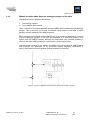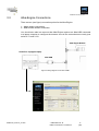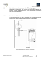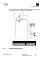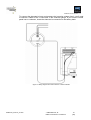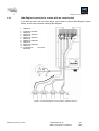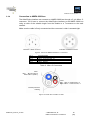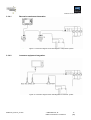
1
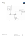
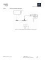
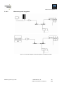
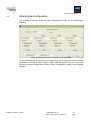
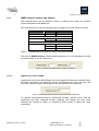
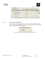
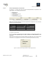
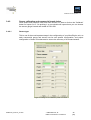
EMMI-CPI_ACSv14_07-003 Albatross Control System v1.4 Albatross Alba-Engine R1_4 interface Manual PRELIMINARY Rev.PA4 EMMI Network SL Albatross Control System v1.4 No part of this document may be reproduced in any form without the written permission of the copyright owner. The contents of this document are subject to revision without notice due to continued progress in methodology, design and manufacturing. EMMI Network SL shall have no liability for any error or damage of any kind resulting from the use of this document. The information provided in this document concerning capacity, suitability and performance shall not be considered commercially binding. Please note that all capacity figures and dimensioning methods are based on EMMI Network’s SL own models of how devices behave in a network. The document is intended to be used by professionally trained personnel. It is strongly recommended to involve EMMI Network SL in discussions covering the contents of this document. Any feedback that may help EMMI Network SL improve the documentation and information methods is welcome. EMMI-CPI_ACSv14_07-003 © EMMI Network, SL EMMI Commercial In Confidence 2 (30) EMMI Network SL Albatross Control System v1.4 Contents 1 2 3 Contents...................................................................................................................................................5 1.1 Purpose ........................................................................................................................................... 5 1.2 Review history................................................................................................................................ 5 Introduction.............................................................................................................................................6 2.1 Specifications ................................................................................................................................. 6 2.2 Quick installation ........................................................................................................................... 7 Installation...............................................................................................................................................8 3.1 Unpacking the unit ......................................................................................................................... 8 3.2 Choosing a location to mount the module .................................................................................. 8 3.2.1 3.2.2 3.3 Module location if analogue gauges are already present................................................................................ 9 Module location when there are analogue gauges on the ship..................................................................... 10 Alba-Engine Connections............................................................................................................ 11 3.3.1 3.3.1.1 3.3.1.2 3.3.2 3.3.3 3.3.4 3.3.4.1 3.3.4.2 3.3.4.3 3.3.4.4 3.3.4.5 3.4 Alba-Engine connection to a motor with VDO analogue gauges .................................................................. 12 Connection to a Tachometer ........................................................................................................................ 12 Connection to a pressure or temperature gauge .......................................................................................... 13 Alternator and mass connection ................................................................................................................... 13 Alba-Engine connection to a motor with no control panel ............................................................................. 15 Connection to NMEA 2000 bus .................................................................................................................... 16 Raymarine equipment integration ................................................................................................................. 17 Lowrance equipment integration................................................................................................................... 17 Simrad equipment integration....................................................................................................................... 18 Garmin equipment integration ...................................................................................................................... 19 Albatross system integration......................................................................................................................... 20 Alba-Engine Configuration.......................................................................................................... 21 3.4.1 3.4.1.1 3.4.1.2 3.4.1.3 3.4.2 3.4.2.1 3.4.2.2 3.4.3 NMEA instance number and address ........................................................................................................... 22 Impulses per turn for RPM............................................................................................................................ 22 Send 0 signal when RPM are 0? .................................................................................................................. 23 Choice of parameters to be measured.......................................................................................................... 24 Sensor calibration and commercial brand choice ......................................................................................... 25 Sensor type .................................................................................................................................................. 25 Voltage correction enabled? ......................................................................................................................... 26 Custom sensor calibration ............................................................................................................................ 26 3.5 Albatross system upgrades ........................................................................................................ 27 3.6 Maintenance ................................................................................................................................. 28 3.7 Technical specifications.............................................................................................................. 29 3.8 Technical support ........................................................................................................................ 30 3.8.1 3.8.2 3.8.3 Web .............................................................................................................................................................. 30 Customer support hotline.............................................................................................................................. 30 Help us help you ........................................................................................................................................... 30 EMMI-CPI_ACSv14_07-003 © EMMI Network, SL EMMI Commercial In Confidence 3 (30) EMMI Network SL Albatross Control System v1.4 Figures table Figure 01. Module mounting ..............................................................................................................................8 Figure 02. Wiring diagram from the module to the motor sensors .....................................................................9 Figure 03. Connection diagram of the module in parallel with analogue gauges .............................................10 Figure 04 Wiring diagram to the Alba-USB ......................................................................................................11 Figure 05. Wiring diagram of the module to a VDO tachometer......................................................................12 Figure 06. Wiring diagram of the module to a VDO pressure or temperature analogue gauge........................13 Figure 07. Wiring diagram from the module to a VDO voltmeter......................................................................14 Figure 08. Connection Diagram of the module to resistive sensors .................................................................15 Figure 09. View of the NMEA 2000 Micro-C connectors ..................................................................................16 Figure 10. Inside view of a Micro-C cable ........................................................................................................16 Figure 11.Connection diagram of the Alba-Engine to a Raymarine system .....................................................17 Figure 12.Connection diagram of the Alba-Engine to a Lowrance system......................................................17 Figure 13. Connection diagram of the Alba-Engine to a Simrad system ..........................................................18 Figure 14. Connection diagram of the Alba-Engine to a Garmin system..........................................................19 Figure 15. Connection diagram of the Alba-Engine to an Albatross System....................................................20 Figure 16. Main dialog box for the configuration of the Alba-Engine................................................................21 Figure 17. Detail of the NMEA instance number and addres ...........................................................................22 Figure 18. Detail of the impulses per turn for the calibration of RPM field........................................................22 Figure 19. Screen showing the RPM information sent by the motor during the calibration proces .................23 Figure 20. Detail of the behaviour when the motor stopped configuration field................................................23 Figure 21. Detail of the configuration of parameters to be measured by the module .......................................24 Figure 22. Detail of the sensor type (resistive or VDO) configuration field ......................................................24 Figure 23. Dialog box for calibration points in a sensor....................................................................................25 Figure 24. General diagram of possible upgrades to the Albatross system .....................................................27 EMMI-CPI_ACSv14_07-003 © EMMI Network, SL EMMI Commercial In Confidence 4 (30) EMMI Network SL Albatross Control System v1.4 1 Contents 1.1 Purpose The purpose of this document is to provide the user with the necessary instructions for the installation and usage of the NME A2000 Albatross Alba-Engine interface. The NME A2000 Albatross Alba- Engine is a device intended to monitor NME A2000 marine motors. The following handbook deals with the Alba-Engine firmware version 1.20. 1.2 Review history Review Date Comments/Changes PA1 2006-11-28 First version PA2 2006-12-22 Minor updates PA3 2007-01-02 Connection diagram to VDO gauges updated PA4 2007-01-22 Format review Table 1 Revision History EMMI-CPI_ACSv14_07-003 © EMMI Network, SL EMMI Commercial In Confidence 5 (30) EMMI Network SL 2 Albatross Control System v1.4 Introduction Thanks for purchasing the new Albatross digital control system component. The following handbook contains important information regarding the installation, operation and maintenance of your new digital control system. In order to get the best results from the unit, please read this handbook thoroughly. 2.1 Specifications The Albatross Alba-Engine interface has the following specifications: EMMI-CPI_ACSv14_07-003 NMEA 2000 interface Adapts standard (10-180 ohm) European resistive sensors to the NMEA 2000 network. Adapts standard (30-240 ohm) American resistive sensors to the NMEA 2000 network. Adapts non-standard resistive sensors () to the NMEA 2000 network Adapts VDO technology- equipped sensors (0-5 V) to the NMEA 2000 network Can be calibrated both in resistive and voltage modes. Can work in parallel with already installed analogue gauges or connected directly to sensors (in motors without a control panel) Motor RPM measurement Alternator tension measuring Oil pressure measuring Boost pressure measuring Cooling agent temperature measuring Oil temperature measuring Cooling water pressure measuring © EMMI Network, SL EMMI Commercial In Confidence 6 (30) EMMI Network SL 2.2 Albatross Control System v1.4 Quick installation To install the Alba-Engine interface, you must complete the following steps. Please study each referenced individual section for in-depth information on each of them: 1 2 3 4 5 6 Unpacking the box. Choose a location for the interface installation. Connect the interface. Interface configuration. Sensor calibration depending on its commercial model. Optional: Custom sensor calibration EMMI-CPI_ACSv14_07-003 © EMMI Network, SL EMMI Commercial In Confidence 7 (30) EMMI Network SL Albatross Control System v1.4 3 Installation 3.1 Unpacking the unit When you unpack the box containing your Albatross Alba-Engine interface, you should find the following elements: Alba-Engine interface Alba-Engine User Manual Bag with the mounting screws If any of these elements is damaged or not present, please contact Emmi network 3.2 Choosing a location to mount the module Figure 1. Module mounting.g EMMI-CPI_ACSv14_07-003 © EMMI Network, SL EMMI Commercial In Confidence 8 (30) EMMI Network SL 3.2.1 Albatross Control System v1.4 Module location if analogue gauges are already present Alba-Engine has two types of connection: 1 – Motor sensors connection 2 – NMEA 2000 network connection Thus, the Alba-Engine interface should be placed between the main NMEA 2000 network and the analogue gauges. This is because you'll have to connect some wires from the interface to the back of the gauges and others to the NMEA network. Emmi network recommends putting the Alba- Engine at a maximum distance of 4 metres from the motor sensors. The Alba-Engine interface should be connected to the main network at a maximum distance of 6 metres, although the user should consider putting it as close to the main NMEA network as possible to save in cable costs. Placing of the interface is not critical and taking into account the aforementioned distances and that all NMEA cables and connections are water-proof (IP67, protected against temporary immersions in water), the interface could be located virtually anywhere in the ship. Figure 2. Wiring diagram from the module to the motor sensors EMMI-CPI_ACSv14_07-003 © EMMI Network, SL EMMI Commercial In Confidence 9 (30) EMMI Network SL 3.2.2 Albatross Control System v1.4 Module location when there are analogue gauges on the ship. Alba-Engine has two kinds of connections: 1 – To the motor sensors 2 – To the NMEA 2000 network Thus, it should be connected between the main NMEA-2000 network and the analogue gauges. This is because you’ll have to connect some cables to the back of these gauges, and the interface to the NMEA network. Emmi network recommends putting Alba-Engine at a maximum distance of 4 metres from the analogue gauges. It can also be connected to a maximum distance of 6 metres from the NMEA network, although the ship-owner may consider installing it closer to the main NMEA network in order to save on the cost of cable. Interface install location is not critical, and taking into account that all NMEA cables and connector are watertight (IP 67: protection against temporary immersions in water), the interface could be placed virtually anywhere on the ship. Figure 3. Connection diagram of the module in parallel with analogue gauges EMMI-CPI_ACSv14_07-003 © EMMI Network, SL EMMI Commercial In Confidence 10 (30) EMMI Network SL 3.3 Albatross Control System v1.4 Alba-Engine Connections There are two (see figure) connection points for the Alba-Engine: 1 – Motor sensor connections 2 – NMEA 2000 network connection You should also take into account that Alba-Engine requires an Alba-USB connected to a laptop computer to configure the sensors once all the connections are ready (see points 2.3.1 and 2.3.2) Alba-Engine Module InstallTool- equipped Laptop Alba-USB Figure 4 Wiring diagram to the Alba-USBB EMMI-CPI_ACSv14_07-003 © EMMI Network, SL EMMI Commercial In Confidence 11 (30) EMMI Network SL 3.3.1 Albatross Control System v1.4 Alba-Engine connection to a motor with VDO analogue gauges Alba-Engine can work together with analogue motor gauges without affecting their measuring. To make this kind of connection you will have to follow the instructions given in the following illustrations 3.3.1.1 Connection to a Tachometer For this type of connection you'll need to derive a wire from the (orange-coloured) one marked W in the gauge, connecting it to input number 2 in the Alba-Engine. + - 1 - Signal G + - 2 - Ground Figure 5. Wiring diagram of the module to a VDO tachometer. EMMI-CPI_ACSv14_07-003 © EMMI Network, SL EMMI Commercial In Confidence 12 (30) EMMI Network SL 3.3.1.2 Albatross Control System v1.4 Connection to a pressure or temperature gauge You'll need to unscrew the connector’s nut in these gauges and hook a new cable to be connected to either the 4, 6, 8 or 10 inputs in the Alba-Engine. Figure 6. Wiring diagram of the module to a VDO pressure or temperature analogue gauge. Gauge terminals Proposed cable colour Tension (+, +12V, I, IGN) Red Black Green Ground (-, ⊥,G) Sensor (S, G) Table 1. Standard gauge connectors 3.3.2 Alternator and mass connection EMMI-CPI_ACSv14_07-003 © EMMI Network, SL EMMI Commercial In Confidence 13 (30) EMMI Network SL Albatross Control System v1.4 To connect the alternator’s input and measure the incoming voltage from it, you’ll need to connect a cable to the +V connector in the voltmeter gauge. If your motor’s control panel has no voltmeter, locate the alternator’s connection to the battery bank. Figure 7. Wiring diagram from the module to a VDO voltmeter EMMI-CPI_ACSv14_07-003 © EMMI Network, SL EMMI Commercial In Confidence 14 (30) EMMI Network SL 3.3.3 Albatross Control System v1.4 Alba-Engine connection to a motor with no control panel If you have a motor with no control panel, you’ll need to connect Alba-Engine’s inputs directly to the motor sensors following this diagram: 123456789101112- NEGATIVE W SIGNAL/ SENSOR NEGATIVE RESISTIVE SENSOR NEGATIVE RESISTIVE SENSOR NEGATIVE RESISITIVE SENSOR NEGATIVE RESISITIVE SENSOR NEGATIVE ALTERNATOR VOLTAGE MEASURE Figure 8. Connection Diagram of the module to resistive sensors s EMMI-CPI_ACSv14_07-003 © EMMI Network, SL EMMI Commercial In Confidence 15 (30) EMMI Network SL 3.3.4 Albatross Control System v1.4 Connection to NMEA 2000 bus The Alba-Engine interface can connect to a NMEA 2000 bus through a 5- pin Micro- C connector. You’ll have to connect the Alba-Engine interface to the NMEA 2000 bus using a cable of the suitable length from the module to a T-connector to the main network. Make sure the cable is firmly connected and the connector’s collar is screwed tight. Illustration 1 Male connector Illustration 2 Female connector Figure 9. View of the NMEA 2000 Micro-C connectors Pin 1: Pin 2: Pin 3: Pin 4: Pin 5: Protective Braid NET-S. (Positive feed, +V) NET-C. (Common feed, -V) NET-H. (CAN-H) NET-L. (CAN-L) Table 2. Micro-C Connectors Data: Blue : NET-H (CAN-H) White: NET-L.(CAN-L) Feed: Red : NET-S. Positive feed, +V Black: NET-C. Common Feed, -V External protective braiding Figure 10. Inside view of a Micro-C cable EMMI-CPI_ACSv14_07-003 © EMMI Network, SL EMMI Commercial In Confidence 16 (30) EMMI Network SL 3.3.4.1 Albatross Control System v1.4 Raymarine equipment integration Figure 11.Connection diagram of the Alba-Engine to a Raymarine system 3.3.4.2 Lowrance equipment integration. Figure 12.Connection diagram of the Alba-Engine to a Lowrance system EMMI-CPI_ACSv14_07-003 © EMMI Network, SL EMMI Commercial In Confidence 17 (30) EMMI Network SL 3.3.4.3 Albatross Control System v1.4 Simrad equipment integration Figure 13. Connection diagram of the Alba-Engine to a Simrad system EMMI-CPI_ACSv14_07-003 © EMMI Network, SL EMMI Commercial In Confidence 18 (30) EMMI Network SL 3.3.4.4 Albatross Control System v1.4 Garmin equipment integration Figure 14. Connection diagram of the Alba-Engine to a Garmin system EMMI-CPI_ACSv14_07-003 © EMMI Network, SL EMMI Commercial In Confidence 19 (30) EMMI Network SL 3.3.4.5 Albatross Control System v1.4 Albatross system integration. Figure 15. Connection diagram of the Alba-Engine to an Albatross System. EMMI-CPI_ACSv14_07-003 © EMMI Network, SL EMMI Commercial In Confidence 20 (30) EMMI Network SL 3.4 Albatross Control System v1.4 Alba-Engine Configuration The following illustration shows the main configuration screen for the Alba-Engine interface. Figure 16. Main dialog box for the configuration of the Alba-Engine To ensure the proper functioning of your ship, you need to configure each and every parameter in this dialog before using it. DON’T USE this product until you have gone through the whole configuration process, which is explained in detail in the following sections. EMMI-CPI_ACSv14_07-003 © EMMI Network, SL EMMI Commercial In Confidence 21 (30) EMMI Network SL 3.4.1 Albatross Control System v1.4 NMEA instance number and address Most manufacturers use an instance number to reference the motor the interface inserts data about in the NMEA bus. We recommend you to use the following table to assign the correct instance number. Number of motors Motor Instance number 1 - 0 2 Port 0 Starboard 1 Port 0 Central Starboard 2 1 3 Table 3. Correspondence of instance number and motor location. The device’s NMEA address is automatically assigned, so it is not advisable to modify the value shown for it in the dialog box. Figure 17. Detail of the NMEA instance number and address 3.4.1.1 Impulses per turn for RPM Impulses per turn tell the Alba-Engine how many signals the alternator receives before the motor completes a revolution per minute. 100 impulses per turn is the norm, but this value may vary slightly, depending on the manufacturer of the alternator. Figure 18. Detail of the impulses per turn for the calibration of RPM field To calibrate this parameter having a tachometer installed, start the motor, note the tachometer and main configtool screen’s readings, and change this value while checking the interface’s values on configtool’s initial screen to adjust the value accordingly. EMMI-CPI_ACSv14_07-003 © EMMI Network, SL EMMI Commercial In Confidence 22 (30) EMMI Network SL Albatross Control System v1.4 Figure 19. Screen showing the RPM information sent by the motor during the calibration process 3.4.1.2 Send 0 signal when RPM are 0? You’ll notice in some displays that when the motor is stopped while electric supply is still on, the dials in the digital gauges will go to the maximum value. If this is the case, click on the toggle box to avoid this behaviour. Figure 20. Detail of the behaviour when the motor stopped configuration field. EMMI-CPI_ACSv14_07-003 © EMMI Network, SL EMMI Commercial In Confidence 23 (30) EMMI Network SL 3.4.1.3 Albatross Control System v1.4 Choice of parameters to be measured On inputs 2, 3, 4 and 5 the user can choose what parameters to represent on the digital display. The available parameters are: Boost pressure Oil pressure Coolant water pressure Oil temperature Coolant water temperature Figure 21. Detail of the configuration of parameters to be measured by the module. Make sure the signal cable for each chosen parameter corresponds to the connector number from the following table: Configtool input Parameter Input 1 Input 2 Input 3 Input 4 Input 5 Input 6 RPM Pressure or Temperature Pressure or Temperature Pressure or Temperature Pressure or Temperature Alternator voltage Alba-Engine connector number Connectors 1 and 2 Connector 4 Connector 6 Connector 8 Connector 10 Connector 12 Table 4. Alba-engine inputs and connector number correspondence 3.4 Choice of sensor type As seen in section 2, motor sensors are either resistive or voltage-based (VDO). You must choose the appropriate type of sensor connected for each parameter to be measured. Once you have changed all the necessary fields in the dialog box, click “Accept” for all information to be programmed and stored in the Alba-Engine interface’s memory. Figure 22. Detail of the sensor type (resistive or VDO) configuration field EMMI-CPI_ACSv14_07-003 © EMMI Network, SL EMMI Commercial In Confidence 24 (30) EMMI Network SL 3.4.2 Albatross Control System v1.4 Sensor calibration and commercial brand choice Once sensor and measure units have been chosen, it’s time to click on the “Calibrate” button for inputs 2 to 5. On pushing it, a new window will open where you can choose the sensor gauge’s brand and model to FOLLOW. 3.4.2.1 Sensor type This is one of the most important steps in the configuration of your Alba-Engine unit, as each commercial gauge and sensor has its own specific configuration, and proper configuration of these is fundamental to ensure the accuracy of its measurements. Figure 23. Dialog box for calibration points in a sensor. EMMI-CPI_ACSv14_07-003 © EMMI Network, SL EMMI Commercial In Confidence 25 (30) EMMI Network SL 3.4.2.2 Albatross Control System v1.4 Voltage correction enabled? If you connected the Alba-Engine in parallel with VDO gauges, you’ll have to note the tension at which the configuration is being set in this field (see the initial screen of Installtool, Figure 4) and check the toggle box marked “enabled”. You’ll also have to enter the voltage value at which the measurement was made (in figure 23, the example is 12,29 V) Reference voltage By checking this field, you’ll tell Alba-Engine that the voltage your ship works on may change during its functioning, and this will allow you to adjust the gauges’ readings for maximum accuracy at any time. 3.4.3 Custom sensor calibration Sensors connected to the Alba- Engine module may need calibration for any of the following reasons: 1 – A resistive or non-standard tension sensor is being used 2 – A standard sensor is in use, but maximum accuracy is desired. Annex 1 to this handbook shows you an in-depth explanation of this process. EMMI-CPI_ACSv14_07-003 © EMMI Network, SL EMMI Commercial In Confidence 26 (30) EMMI Network SL 3.5 Albatross Control System v1.4 Albatross system upgrades The Albatross Control System allows you to easily incorporate new characteristics and functions by installing software upgrades and expanding their licenses. Albatross Control System includes a digital onboard control system tool and remote ship safety, positioning and monitoring services. Albatross adapts to the needs of ship-owners who care for onboard safety, and is flexible enough to adapt to ships of any kind and length. Figure 24. General diagram of possible upgrades to the Albatross system . For further information, please visit: www.emminet.com EMMI-CPI_ACSv14_07-003 © EMMI Network, SL EMMI Commercial In Confidence 27 (30) EMMI Network SL 3.6 Albatross Control System v1.4 Maintenance Once installed and configured, there are no specific maintenance measures to be taken. Periodically examine all the components of your Albatross system, including sensors and wiring, looking for signs of wear or damage. Repair them if needed. 3.6.1 Troubleshooting All Albatross products go through exhaustive functioning and quality tests. However, if any problem appears, the following table may help you identify the cause and find a solution for it. Problem Possible cause Solution Albatross modules show no sign of activity (red LED is off) Supply or connection failure Albatross modules seem to be blocked (red LED is always on) Connection failure among modules or the NMEA bus ender is missing Module configuration is incorrect Check electric supply connection Verify Check use or protecting circuit. Check all connections among the modules Check all connections and the existence of at least one network ender. Check module/s configuration Information shown on displays or visualization clients is incorrect A certain type of data (e.g.: battery tension) is missing on the display or visualization clients Sensor information is missing Check sensor Check connections form the sensor to the Albatross module Table 5. Common problems and their possible solution EMMI-CPI_ACSv14_07-003 © EMMI Network, SL EMMI Commercial In Confidence 28 (30) EMMI Network SL 3.7 Albatross Control System v1.4 Technical specifications SPECIFICATIONS Magnetic sensor / W signal Input 4 x Resistive sensor (0 to 250 Ohm) DC tension:. 32V DC max. RPM: ±100rpm Accuracy Resistive sensor: 1% DC tension: 1% NMEA2000 Parameter Group Numbers (PGN’s) Periodic Information PGN127488 Eng.Pa. Rapid Update PGN127489 Eng. Param. Dynamic PGN 126464 Tx/Rx PGN List PGN 126996 Product Information PGN 059392 ISO Acknowledge PGN 059904 ISO Request Control PGN 060928 ISO Address Claim PGN 126208 NMEA Request Group PGN 126720 Proprietary fast-packet ELECTRIC SPECIFICATIONS Tension 9-16V DC from the NMEA bus Consumption <140mA Equivalent load 3 LEN depending on NMEA2000 MECHANICAL SPECIFICATIONS Size & Weight 143mm x 86mm x 38mm , 230g. Weight 230g Mounting Surface, screwed on Case material Polycarbonate UL94V0 ENVIROMENTAL SPECIFICATIONS Water tightness IP54 Working temperature -15ºC a +55ºC Storage temperature -25ºC a +85ºC Relative humidity 93% RH @ 40ºC Vibration 2-13.2Hz @ ±1mm 2 13.2-100Hz @ 7m/s IEC60945-8.7 Salt mist Corrosion 4x7days@40ºC, 95%RH after two hours salt spray IEC609458.12 E.M.C. EMMI-CPI_ACSv14_07-003 per IEC60945-8.3 Emission IEC60945-9 Immunity IEC60945-10 © EMMI Network, SL EMMI Commercial In Confidence 29 (30) EMMI Network SL 3.8 Albatross Control System v1.4 Technical support Emmi Network provides the user with complete technical support through its webpage and a customer support hotline. Please use any of these means to contact us if a problem should rise that you can’t solve. 3.8.1 Web Please visit the customer support area in our webpage: www.emminet.com 3.8.2 Customer support hotline. If you happen not to have Internet access, please call the following phone number: +34 902 010 759 3.8.3 Help us help you Whenever you require any technical assistance, please keep the following information at hand. EMMI-CPI_ACSv14_07-003 Equipment type Serial numbers Installed software version © EMMI Network, SL EMMI Commercial In Confidence 30 (30)