1
WATSON-MARLOW BREDEL MANUALS
m-323dz-gb-04
Watson-Marlow
323Dz pumps
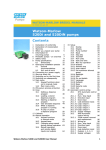
Contents
1
2
3
4
5
6
7
8
9
10
11
12
13
14
15
Declaration of conformity
Declaration of incorporation
Two-year warranty
When you unpack your pump
Information for returning pumps
Peristaltic pumps: an overview
Safety notes
Pump specifications
8.1
Pump features
8.2
Dimensions
Good pump installation practice
9.1
General recommendations
9.2
Do’s and do not’s
Connecting this product
to a power supply
Start-up check list
Switching the pump on
for the first time
Switching the pump on
in subsequent power cycles
(if not in auto-restart mode)
Auto-restart facility
The main menu
15.1 Setup
15.1.1 ROM version
15.1.2 Display backlight
15.1.3 Factory defaults
15.1.4 Language
15.1.5 Menu
15.2 Manual control
15.3 Calibration
15.4 Dose
15.4.1 Dose volume
15.4.2 Dose interval
15.4.3 Number of doses
15.4.4 Pump speed
15.4.5 Pump direction
15.4.6 Start ramp
15.4.7 End ramp
15.4.8 Drip
15.4.9 Proceed
15.4.10 Single dose
dispensing
15.4.11 Batch dispensing
15.5 Remote control
Watson-Marlow 323Dz User Manual
2
2
3
4
5
6
7
9
9
14
15
15
16
17
18
18
19
20
21
22
22
22
22
23
23
24
26
28
30
30
31
31
32
32
33
33
34
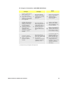
16 Troubleshooting
16.1 Error messages
17 Drive maintenance
18 Drive part numbers
19 Drive spares
20 Accessories
21 Pumpheads
21.1 Pumpheads: key
safety information
21.2 313D and 314D
pumpheads
21.3 313D and 314D
pumphead spares
21.4 313D and 314D
flow rates
21.5 313D and 314D:
maximum number of
pumpheads
21.6 313D and 314D:
tubing part numbers
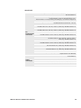
21.7 501RL pumphead
21.8 501RL and 501RL2
installation
21.9 501RL and 501RL2
tube loading
21.10 501RL and 501RL2
rotor settings
21.11 501RL and 501RL2
pumphead spares
21.12 501RL and 501RL2
flow rates
21.13 501RL and 501RL2:
tubing part numbers
22 Trademarks
23 Warning not to use pumps in
patient-connected applications
24 Publication history
25 Decontamination certificate
38
39
40
40
41
41
42
42
42
44
45
46
47
48
48
48
49
50
51
51
52
52
52
53
34
35
38
1
1 Declaration of conformity
This declaration was issued for Watson-Marlow 323Dz pumps on November 1, 2007. When this pump unit is used as a stand-alone pump it complies with: Machinery Directive 2006/42/EC, EMC Directive 2004/108/EC.
This pump is ETL listed: ETL control number 3050250. Cert to CAN/CSAstd
C22.2 No 61010-1. Conforms to UL std 61010A-1.
See 8 Pump specifications.
2 Declaration of incorporation
When this pump unit is to be installed into a machine or is to be assembled with other
machines for installations, it must not be put into service until the relevant machinery has been declared in conformity with the Machinery Directive 2006/42/EC.
Responsible person: Christopher Gadsden, Managing Director, Watson-Marlow Limited, Falmouth, Cornwall TR11 4RU, England. Telephone +44 (0) 1326 370370 Fax
+44 (0) 1326 376009.
The information in this user guide is believed to be correct at the time of publication.
However, Watson-Marlow Limited accepts no liability for errors or omissions. WatsonMarlow Bredel has a policy of continuous product improvement, and reserves the
right to alter specifications without notice. This manual is intended for use only with
the pump it was issued with. Earlier or later models may differ. The most up-to-date
manuals appear on the Watson-Marlow website: http://www.watson-marlow.com
Watson-Marlow 323Dz User Manual
2
3 Two-year warranty
Watson-Marlow Limited ("Watson-Marlow") warrants, subject to the conditions and
exceptions below, through either Watson-Marlow, its subsidiaries, or its authorised
distributors, to repair or replace free of charge, any part of the product which fails
within two years of the day of manufacture of the product. Such failure must have occurred because of defect in material or workmanship and not as a result of operation
of the product other than in normal operation as defined in this pump manual.
Watson-Marlow shall not be liable for any loss, damage, or expense directly or indirectly related to or arising out of the use of its products, including damage or injury
caused to other products, machinery, buildings, or property, and Watson-Marlow shall
not be liable for consequential damages, including, without limitation, lost profits,
loss of time, inconvenience, loss of product being pumped, and loss of production.
This warranty does not obligate Watson-Marlow to bear any costs of removal, installation, transportation, or other charges which may arise in connection with a warranty claim.
Conditions of and specific exceptions to the above warranty are:
Conditions
Products must be returned by pre-arrangement, carriage-paid, to Watson-Marlow, or a Watson-Marlow approved service centre.
All repairs or modifications must have been made by Watson-Marlow Limited, or
a Watson-Marlow approved service centre or with the express permission of
Watson-Marlow.
Warranties purporting to be on behalf of Watson-Marlow made by any person,
including representatives of Watson-Marlow, its subsidiaries, or its distributors,
which do not accord with the terms of this warranty shall not be binding upon
Watson-Marlow unless expressly approved in writing by a Director or Manager of
Watson-Marlow.
Exceptions
The warranty shall not apply to repairs or service necessitated by normal wear
and tear or for lack of reasonable and proper maintenance.
All tubing and pumping elements as consumable items are excluded.
Products which, in the judgment of Watson-Marlow, have been abused, misused,
or subjected to malicious or accidental damage or neglect are excluded.
Electrical surge as a cause of failure is excluded.
Chemical attack is excluded
All pumphead rollers are excluded.
Pumpheads from the 313/314 retain their one-year standard pumphead warranty. The drive they are attached to is subject to the two-year warranty as set
out here.
Ancillaries such as leak detectors are excluded.
Watson-Marlow 323Dz User Manual
3
4 When you unpack your pump
Unpack all parts carefully, retaining the packaging until you are sure all components
are present and in good order. Check against the components supplied list, below.
Packaging disposal
Dispose of packaging materials safely, and in accordance with regulations in your
area. The outer carton is made of corrugated cardboard and can be recycled.
Inspection
Check that all components are present. Inspect components for damage in transit. If
anything is missing or damaged, contact your distributor immediately.
Components supplied
Watson-Marlow 323Dz pumps are supplied as:
Dedicated 323Dz pump drive unit fitted with one or more 313 or 314 pumpheads or a 501RL pumphead (see 8 Pump specifications).
The designated mains power lead for your pump
PC-readable CDROM containing these operating instructions
Quick Start manual
Note: Some versions of this product will include components different from those
listed above. Check against your purchase order.
Storage
This product has an extended shelf life. However, care should be taken after storage
to ensure that all parts function correctly. Users should be aware that the pump contains a battery with an unused life of seven years. Long-term storage is not recommended for peristaltic pump tubing. Please observe the storage recommendations
and use-by dates which apply to tubing you may wish to bring into service after storage.
Watson-Marlow 323Dz User Manual
4
5 Information for returning pumps
Equipment which has been contaminated with, or exposed to, body fluids, toxic chemicals or any other substance hazardous to health must be decontaminated before it
is returned to Watson-Marlow or its distributor.
A certificate included at the rear of these operating instructions, or signed statement,
must be attached to the outside of the shipping carton. This certificate is required
even if the pump is unused. See 25 Decontamination certificate.
If the pump has been used, the fluids that have been in contact with the pump and
the cleaning procedure must be specified along with a statement that the equipment
has been decontaminated.
Watson-Marlow 323Dz User Manual
5
6 Peristaltic pumps - an overview
Peristaltic pumps are the simplest pump, with no valves, seals or glands to clog or
corrode. The fluid contacts only the bore of a tube, eliminating the risk of the pump
contaminating the fluid, or the fluid contaminating the pump. Peristaltic pumps can
run dry.
How they work
A compressible tube is squeezed between a roller and a track on an arc of a circle,
creating a seal at the point of contact. As the roller advances along the tube, the seal
also advances. After the roller has passed, the tube returns to its original shape, creating a partial vacuum which is filled by fluid drawn from the inlet port.
Before the roller reaches the end of the track, a second roller compresses the tube
at the start of the track, isolating a packet of fluid between the compression points.
As the first roller leaves the track, the second continues to advance, expelling the
packet of fluid through the pump’s discharge port. At the same time, a new partial
vacuum is created behind the second roller into which more fluid is drawn from the
inlet port.
Backflow and siphoning do not occur, and the pump effectively seals the tube when
it is inactive. No valves are needed.
The principle may be demonstrated by squeezing a soft tube between thumb and finger and sliding it along: fluid is expelled from one end of the tube while more is drawn
in at the other.
Animal digestive tracts function in a similar way.
Suitable applications
Peristaltic pumping is ideal for most fluids, including viscous, shear-sensitive, corrosive and abrasive fluids, and those containing suspended solids. They are especially
useful for pumping operations where hygiene is important.
Peristaltic pumps operate on the positive displacement principle. They are particularly
suitable for metering, dosing and dispensing applications. Pumps are easy to install,
simple to operate and inexpensive to maintain.
Watson-Marlow 323Dz User Manual
6
7 Safety notes
In the interests of safety, this pump and the tubing selected should only be used by
competent, suitably trained personnel after they have read and understood this manual, and considered any hazard involved. If the pump is used in a manner not specified by Watson-Marlow Limited, the protection provided by the pump may be
impaired.
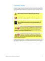
This symbol, used on the pump and in this manual,
means: Caution, refer to accompanying documents.
This symbol, used on the pump and in this manual,
means: Do not allow fingers to contact moving parts.
This symbol, used on the pump and in this manual,
means: Recycle this product under the terms of the EU
Waste Electrical and Electronic Equipment (WEEE) Directive.
There is a user-replaceable type T1.0AH 250V fuse
in the fuse drawer of the IEC mains connector at
the back of the pump, which also contains a spare
fuse. In some countries, the mains power plug
contains an additional replaceable fuse. There are no user-serviceable fuses or parts inside this pump.
Fundamental work with regard to lifting, transportation, installation, starting-up, maintenance
and repair should be performed by qualified personnel only. The unit must be isolated from mains power while
work is being carried out.
Any person who is involved in the installation or periodic maintenance of this equipment should be suitably skilled or instructed and supervised using a safe system of
work. In the UK this person should also be familiar with the Health and Safety at
Work Act 1974.
Watson-Marlow 323Dz User Manual
7
There are moving parts inside the pumphead. Before opening the track, ensure that the following safety directions are followed.
Ensure that the pump is isolated from the mains power.
Ensure that there is no pressure in the pipeline.
If a tube failure has occurred, ensure that any fluid in the pumphead has been
allowed to drain to a suitable vessel, container or drain.
Ensure that protective clothing and eye protection are worn if hazardous fluids
are pumped.
Primary operator protection from rotating parts of the pump is provided by the
pumphead track. See 21 Pumpheads.
This product does not comply with the ATEX directive
and must not be used in explosive atmospheres.
This pump must be used only for its intended purpose. The pump must be accessible
at all times to facilitate operation and maintenance. Access points must not be obstructed or blocked. The pump’s mains plug is the disconnecting device (for isolating
the motor drive from the mains supply in an emergency). Do not position the pump
so that it is difficult to disconnect the mains plug. Do not fit any devices to the drive
unit other than those tested and approved by Watson-Marlow. Doing so could lead to
injury to persons or damage to property for which no liability can be accepted.
If hazardous fluids are to be pumped, safety procedures specific to the particular fluid
and application must be put in place to protect against injury to persons.
The exterior surfaces of the pump may get hot during operation. Do not take hold of
the pump while it is running. Let it cool after use before handling it.
No attempt should be made to run the drive without a pumphead fitted.
Watson-Marlow 323Dz User Manual
8
8 Pump specifications
Labels fixed to the rear of the pump contain manufacturer and contact details,
product reference number, serial number and model details.
8.1 Pump features
This pump can be controlled from the keypad (or a footswitch for dosing). It features:
Manual control
Speed adjustment; run and stop; direction control.
Remote control
Dose starts can be controlled with a contact closure or logic input signal.
Dispensing
The pump dispenses measured volumes of fluid as single doses, batches or as a
timed sequence of doses. Ramp and drip control.
High-speed model
323Dz with 313D three-roller flip-top pumphead: maximum speed 400 rpm; or 314D
four-roller flip-top pumphead: maximum speed 300 rpm; for 1.6mm wall thickness
tubing up to 8mm diameter.
Low-speed model
323Dz with 501RL 1.6mm wall tubing pumphead for tubing up to 8mm diameter:
max speed 300 rpm. Note: It is possible to fit 313 and 314 pumpheads to a lowspeed 323Dz drive by the use of an adaptor plate: part no 039.0031.000.
Watson-Marlow 323Dz User Manual
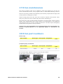
9
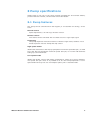
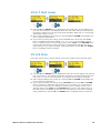
The 323Dz is available with a choice of gearboxes: a long-nosed gearbox, which offers 1-300 rpm and can be fitted with a 501RL or a 501RL2 pumphead, or a 313D/A
or a 314D/A pumphead (which includes an adaptor plate)*; or a short-nosed gearbox, which offers 2-400 rpm and can be fitted with a 313 or 314 pumphead. See 21
Pumpheads for further information.
323Dz
1-300 rpm
2-400 rpm
* 313D/A and 314D/A pumpheads should not be confused with 313DA and 314DA
pumpheads, which are ATEX-compliant models for use in explosive atmospheres.
Watson-Marlow 323Dz User Manual
10
IP (Ingress Protection) and NEMA definitions
IP
1st Digit
3
Protected against
ingress of solid objects
with a diameter of
more than 2.5mm.
Tools, wires etc with a
thickness of more than
2.5mm are prevented
from approach
5
Protected against
harmful dust deposits.
Ingress of dust is not
totally prevented but
the dust must not
enter in sufficient
quantity to interfere
with satisfactory
operation of the
equipment. Complete
protection against
contact
6
Protection against
ingress of dust (dusttight). Complete
protection against
contact
NEMA
2nd Digit
1
5
6
Protection against
dripping water falling
vertically. No harmful
effect must be
produced
Protection against
water projected from a
nozzle against the
equipment (enclosure)
from any direction.
There must be no
harmful effect (water
jet)
Protection against
heavy seas or powerful
water jets. Water must
not enter the
equipment (enclosure)
in harmful quantities
(splashing over)
2
Indoor use to provide a
degree of protection
against limited
amounts of falling
water and dirt
12
Indoor use to provide a
degree of protection
against dust, falling
dirt and dripping, noncorrosive liquids
13
Indoor use to provide a
degree of protection
against dust and spraying of water, oil and
non-corrosive coolants
4X
Indoor or outdoor use*
to provide a degree of
protection against
splashing water, windblown dust and rain,
hose-directed water;
undamaged by the
formation of ice on the
enclosure. (Resist
corrosion: 200-hour
salt spray)
* Protect from prolonged UV exposure.
Watson-Marlow 323Dz User Manual
11
Pump specifications
Supply voltage/frequency
Maximum voltage fluctuation
Installation category
(overvoltage category)
Power consumption
Full load current
Eprom version
Enclosure rating
Operating temperature range
Storage temperature range
Maximum altitude
Humidity (non-condensing)
Weight
Noise
100-120V/200-240V 50/60Hz 1ph
±10% of nominal voltage. A well
regulated electrical mains supply is required along with cable connections conforming to the best practice of noise
immunity
II
100VA
<0.43A at 230V; <0.86A at 115V
Accessible through pump software
IP31 to BS EN 60529; Equivalent to
NEMA 2. Suitable for indoor use. Protected against dripping water and falling
dirt. May be wiped with a damp cloth but
should not be immersed
4C to 40C, 40F to 104F
-40C to 70C, -40F to 158F
2,000m, 6,560ft
80% up to 31C, 88F, decreasing
linearly to 50% at 40C, 104F
See 8.2 Dimensions
<70dB(A) at 1m
Absolute minimum dose size
Two revolutions
Recommended minimum dose size
Five revolutions
Maximum single dose size
9,999 litres
Minimum number of doses
1
Maximum number of doses
9,999
Minimum interval between doses
0.1 second
Maximum interval between doses
999 seconds
Watson-Marlow 323Dz User Manual
12
Standards
Safety of machinery—electrical equipment of machines:
BS EN 60204-1
Safety requirements for electrical equipment for
measurement, control and laboratory use:
BS EN 61010-1 incorporating A2 Category 2, Pollution degree 2
Degrees of protection provided by enclosures (IP code):
BS EN 60529 amendments 1 and 2
Conducted emissions:
BS EN 55011 A1 and A2, Class A, called by BS EN 61000-6-4
EC
harmonised
standards
Radiated emissions:
BS EN 55011 A1 and A2, Class A, called by BS EN 61000-6-4
Electrostatic discharge: BS EN 61000-4-2
Radiated RF immunity:
BS EN 61000-4-3 A1 and A2, called by BS EN 61000-6-2
Fast transient burst:
BS EN 61000-4-4 A1 and A2, Level 3 (2kV),
called by BS EN 61000-6-2
Surge immunity:
BS EN 61000-4-5 A1 and A2, called by BS EN 61000-6-2
Conducted RF immunity:
BS EN 61000-4-6, called by BS EN 61000-6-2
Voltage dips and interruptions:
BS EN 61000-4-11, called by BS EN 61000-6-2
Mains harmonics: BS EN 61000-3-2 A2
Pumps and pump units for liquids—common safety
requirements: BS EN 809
UL 61010A-1
CAN/CSA-C22.2 No 61010-1
Other
standards
Conducted emissions FCC 47CFR, Part 15.107
Radiated emissions FCC 47CFR, Part 15
NEMA 2
Watson-Marlow 323Dz User Manual
13
8.2 Dimensions
Unit weights
323Dz
Watson-Marlow 323Dz User Manual
Drive only
+ 313
+ 501RL
4.5kg, 9lb 15oz
4.8kg, 10lb 9oz
5.5kg, 12lb 2oz
14
9 Good pump installation practice
9.1 General recommendations
Position
A correctly engineered installation will promote long tube life. Site the pump on a
flat, horizontal, rigid surface, free from excessive vibration. Allow a flow of air around
the pump to ensure that heat can be dissipated. Ensure that the temperature around
the pump does not exceed 40C.
Emergency disconnection
The pump’s mains plug is the disconnecting device (for isolating the motor drive from
the mains supply in an emergency). Do not position the pump so that it is
difficult to disconnect the mains plug. The STOP key on the keypad will always stop
the pump. However, it is recommended that a suitable local emergency stop device
is fitted into the mains supply to the pump.
Valves
Peristaltic pumps are self-priming and self-sealing against backflow. No valves are
required in inlet or discharge lines. Valves in the process flow must be opened before
the pump operates. Users are advised to fit a pressure relief device between the pump
and any valve on the discharge side of the pump to protect against damage caused
by accidental operation with the discharge valve closed.
The pump may be set up so that the direction of rotor rotation is clockwise or
counter-clockwise, whichever is convenient. Please note, however, that with a 501RL
pumphead tube life will be greater if the rotor rotates clockwise; and that performance against pressure will be maximised if the rotor rotates counter-clockwise.
Tubing materials: run-in advice
Sta-Pure and Marprene tubing are hard to compress when new. When using
tubing made of these materials, the first 30 seconds should be at a speed of 10 rpm
or greater. If the pump is run slower, the safety system built into pump drive’s software may cause it to stop and display an over-current error message.
Watson-Marlow 323Dz User Manual
15
9.2 Do’s and do not’s
Do operate the pump on a flat horizontal surface. The pump requires a free flow of
air for cooling. Do not block the air vents beneath the pump or at the rear.
Do not stack pumps more than three high.
Do use only single phase mains electricity supplies.
Do keep delivery and suction tubes as short and direct as possible - though ideally
not shorter than 1m - and follow the straightest route. Use bends of large radius: at
least four times the tubing diameter. Ensure that connecting pipework and fittings
are suitably rated to handle the predicted pipeline pressure. Avoid pipe reducers and
lengths of smaller bore tubing than the pumphead section, particularly in pipelines on
the suction side. When pumping viscous fluids use pipe runs with a bore several times
larger than the pump tube. Any valves in the pipeline (not usually needed) must not
restrict the flow. Any valves in the flow line must be open when the pump is running.
Do ensure that on longer tube runs at least 1m of smooth bore flexible tubing is connected to the inlet and discharge port of the pumphead to help to minimize impulse
losses and pulsation in the pipeline. This is especially important with viscous fluids and
when connecting to rigid pipework.
Do site the pump at or just below the level of the fluid to be pumped if possible. This
will ensure flooded suction.
Do keep the pumphead track and all moving parts clean and free from contamination and debris.
Do run at slow speed when pumping viscous fluids. Flooded suction will enhance
pumping performance in all cases, particularly for materials of a viscous nature.
Do recalibrate after changing pump tubes, fluid, or any connecting pipework. It is
also recommended that the pump is recalibrated periodically to maintain accuracy.
When using Marprene or Bioprene continuous tubing, do re-tension the tube after
the first 30 minutes of running.
Tube selection: The chemical compatibility lists published in Watson-Marlow publications are guides. If in doubt about the compatibility of a tube material and the duty
fluid, request a Watson-Marlow tube sample card for immersion trials.
Watson-Marlow 323Dz User Manual
16
10 Connecting this product
to a power supply
A well regulated electrical mains supply is required along with cable connections conforming to the best practice of noise immunity. It is not recommended to site these
drives alongside “dirty” electrical mains supplies such as 3-phase contactors and inductive heaters without special attention being paid to unacceptable mains-borne
noise.
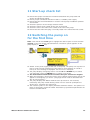
The voltage selector is mounted in the switchplate at the rear of
the pump. Set the voltage selector to 115V for 100-120V
50/60Hz supplies or 230V for 200-240V 50/60Hz supplies. Always check the voltage selector switch before connecting the
mains supply. Make suitable connection to an earthed, singlephase mains electricity supply. To comply with Safety Standards,
the mains plug must be a separable plug (not a locking type).
We recommend using commercially available supply
voltage surge suppression where there is excessive electrical noise.
Input line fusing: type T1.0AH 250V 20mm time-delayed cartridge fuse, located in
the combined mains IEC inlet socket and fuse drawer at the rear of the pump.
Note: A spare fuse is also provided in the drawer.
Conductor coding
European
North American
live
brown
black
neutral
blue
white
ground
green/yellow
green
Watson-Marlow 323Dz User Manual
17
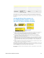
11 Start-up check list
Ensure that proper connections are achieved between the pump tube and
suction and discharge piping.
Ensure proper connection has been made to a suitable power supply.
Ensure that the recommendations in section 9 Good pump installation practice
are followed.
Check the position of the voltage selector switch
Check the mains power switch at the rear of the pump
Check the fuse in the mains inlet socket at the rear of the pump
Ensure that the mains IEC plug is correctly fitted in the mains IEC inlet socket
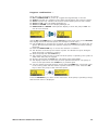
12 Switching the pump on
for the first time
Note: This manual uses bold type to highlight the active option in menu screens:
English” in the first screen represented here. The active option appears on the
pump display in inverse text.
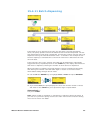
Switch on the power supply at the rear of the pump. The pump runs a power-on
test to confirm proper functioning of the memory and hardware. If a fault is
found, an error message is displayed. See 16.1 Error messages.
The pump displays a language menu. Use the UP and DOWN keys to select
your language. Press the ENTER key to confirm your choice.
The information which follows assumes that your choice was English.
When the language is chosen this menu will not appear again and all menus will
appear in the language you chose. (Language can be reset as described later.
See 15.1.4 Language.)
The pump displays the Watson-Marlow start-up screen for four seconds,
followed by the pump model identity screen for four seconds (examples are
shown here), and then the main menu.
The rotation symbol on the display indicates clockwise rotation. The speed of rotation is the pump's maximum. Other initial start-up operational parameters are
listed in the table below.
Watson-Marlow 323Dz User Manual
18
First-time start-up defaults
Language
Not set
Backlight
On
Speed
Maximum
Auto-restart
Off
Direction
Clockwise
Pump status
Stopped
Calibration
400 rpm:
313, 8mm tube
300 rpm:
501RL, 8mm tube
Beeper
On
The pump is now ready to operate according to the defaults listed above.
All operating parameters may be changed by means of key-presses. See 14 Manual
operation.
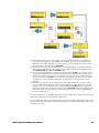
13 Switching the pump on
in subsequent power cycles
(if not in auto-restart mode)
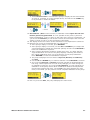
Switch on the power supply at the rear of the pump. The pump runs a power-on
test to confirm proper functioning of the memory and hardware. If a fault is
found, an error message is displayed. See 16.1 Error messages.
The pump displays the Watson-Marlow start-up screen for four seconds,
followed by the pump model identity screen for four seconds (examples are
shown here), and then the main menu.
Note: If any key is pressed during the display of any of the preliminary screens,
the display jumps to the next screen. Quickly pressing any two keys or any key
twice immediately after switch-on causes the display to jump to the main menu.
In the main menu, keys assume their normal functions - see 15.2 Manual control.
Start-up defaults are those in place when the pump was switched off last. Check
that the pump is set to operate as you require it.
The pump is now ready to operate. If the pump starts immediately, look for the
! symbol on the display. This symbol indicates that the pump is set for auto-restart.
Press the STOP key to stop the pump. See 14 Auto-restart.
All operating parameters may be changed by means of key-presses. See 15.2 Manual control.
Watson-Marlow 323Dz User Manual
19
14 Auto-restart facility
Auto-restart will re-start the pump after mains power interruptions.
In auto-restart mode, if the pump was previously dispensing a dose, it returns to
the dose start screen and waits for the START key (or remote dose start switch) to
be pressed.
If the pump was previously under manual control, auto-restart returns the pump to
the last manual setting; stopped if the pump was previously stopped, or running if
the pump was previously running.
The default setting is auto-restart off. Without auto-restart the pump displays the
main menu and waits for a control mode to be selected.
To install auto-restart:
Mains power must be available to the pump to engage auto-restart.
Stop the pump. Turn off the mains power switch at the rear of the pump.
Hold down the START key and turn the mains power switch on. The ! symbol
shows on the display.
Start the pump. If the mains supply is interrupted the pump will automatically
restart when the mains power returns.
Auto-restart is retained while the pump is switched off.
To remove auto-restart switch off the mains power at the rear of the pump. Hold
down the STOP key and turn the mains power switch on. The ! symbol will go
out.
Do not use auto-restart for more than 10 starts per hour.
We recommend remote control where a high number of
starts is required.
Watson-Marlow 323Dz User Manual
20
15 The main menu
In addition to their functions in other operations (see 15.2 Manual control), the following
keys have specific actions in menu screens:
STOP: In general, STOP functions as a
"go back" key, taking the user up one
menu level without making a change. In a
numeric entry screen, STOP resets the
pump to the previous value.
UP: The UP key is used in menu item selection: it moves a highlight up the menu.
When a numerical entry screen is displayed, pressing UP increases the number
displayed.
DOWN: The DOWN key is used in menu
item selection: it moves a highlight down a
menu. When a numerical entry screen is
displayed, pressing DOWN decreases the
number displayed.
START: During Dose setup, press the START key to leave setup and begin the
dose batch via the priming screen. When the priming screen is displayed, press
and hold the START key to operate the pump at full speed and prime the pump.
DIRECTION: During Dose setup, the DIRECTION key reverses the direction of
pump rotation instantly.
RETURN: The RETURN key functions in a similar way to the "enter" key of a
personal computer: it confirms key-presses made immediately before. In menu
item selection, it triggers the action or display selected from a menu using the
UP and DOWN keys.
The options are Dose, Calibrate, Manual, Setup.
Dose programs the pump for dispensing.
Calibrate sets the pump for accurate flow. The flow rate of the pump is governed by the tubing. Factory default is for the 501 pumphead with 8mm bore
tubing or the 313/314 pumphead with 8mm bore tubing.
Manual for keypad control of continuous fluid transfer.
Setup prepares the pump for operation.
Use the UP and DOWN keys to move between the menu options. Press the RETURN
key to select the option.
Press the STOP key to exit a sub-menu and move back up to the previous menu. Or
press the STOP key when changing values on the display to revert to the original
value.
Watson-Marlow 323Dz User Manual
21
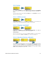
15.1 Setup
Use the UP and DOWN keys to select Setup from the main menu. Press RETURN.
The pump displays the setup menu: ROM, Backlight, Defaults, Language and
Menu.
Scroll through the menu using the UP and DOWN keys. Press RETURN to select the
option you wish to change.
15.1.1 ROM version
Use the UP and DOWN keys to select ROM. Press RETURN. The pump displays the
software version, the pump type and drive speed for four seconds.
15.1.2 Display backlight
Use the UP and DOWN keys to select Backlight. Press RETURN. Use the UP and
DOWN keys to select backlight On or Off. Press RETURN.
Alternatively ...
When not in the Setup menu, hold down the STOP and UP keys to switch the backlight on; hold down the STOP and DOWN keys to switch the backlight off.
15.1.3 Restore factory defaults
This clears any programmed settings and restores the pump to the original factory
settings. Use the UP and DOWN keys to select Defaults. Press RETURN. The pump
displays a brief warning message that all settings will be deleted, and offers a choice:
Restore defaults: Yes or No. Use the UP and DOWN keys to select Yes. Press RETURN. The pump displays the Setup menu.
Watson-Marlow 323Dz User Manual
22
15.1.4 Language
Use the UP and DOWN keys to select Language from the setup menu. Press RETURN. Use the UP and DOWN keys to select English, Français, Deutsch or Español. Press RETURN. The pump displays the setup menu in your chosen language.
It is assumed for the rest of this manual that your choice was English.
15.1.5 Menu
To exit the Setup menu, and return to the main menu, use the UP and DOWN keys
to select Menu. Press RETURN.
Alternatively ...
Press STOP.
Watson-Marlow 323Dz User Manual
23
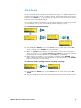
15.2 Manual control
All settings and functions of the pump in manual mode are set and controlled by means of
key-presses. The currently selected rotation direction is indicated on the display by a clockwise or counter-clockwise segmented arrow. If
an exclamation mark ( ! ) shows, it indicates
that Auto-restart is on.
Note: A number of the controls listed below
are shortcuts to commands which are also
available through the main menu. See 15 Main
menu.
A brief single press on each key triggers a
beep sound (if enabled - see Keypress combinations, below) and causes the pump to function as follows:
START: starts the pump at the speed and in the direction shown on the display.
The rotation symbol will become animated to confirm that the pump is operating. We recommend that the speed is reduced to a minimum before starting the
pump.
STOP: has no effect if the pump is not running. If the pump is running, pressing
STOP stops the pump. The display continues to show the previous speed and
direction. The pump returns to this speed and direction when the START key is
pressed again.
UP: increases the speed shown on the display in minimum steps of 1 rpm (unless the speed displayed is already the maximum speed). If the pump is then
started by pressing the START key, it operates at the new speed. If the pump is
running when UP in pressed, the change takes effect immediately.
DOWN: decreases the speed shown on the display in minimum steps of 1 rpm.
If the pump is then started by pressing the START key, it operates at the new
speed. The minimum speed possible is 1 rpm (low speed model) or 2 rpm (high
speed model). If the pump is running when DOWN is pressed, the change takes
effect immediately.
Note: You can reduce the pump speed to 0 rpm by a further press on the
DOWN key. The pump is still in the running state and the rotation symbol will
continue to move. Press the UP key to return the pump to the minimum speed.
DIRECTION: toggles the direction of rotation shown on the display. If the pump
is then started by pressing the START key, it rotates in the new direction. If the
pump is running when DIRECTION is pressed, the change takes effect immediately.
RETURN: stops the pump (if it is running) and displays the main menu.
Watson-Marlow 323Dz User Manual
24
Keypress combinations ...
cause the pump to function as follows:
UP and DIRECTION on power-up: toggles the keypad beep on and off.
START on power-up: switches on the Auto-restart facility. See 14 Auto-restart.
STOP on power-up: switches off the Auto-restart facility. See 14 Auto-restart.
STOP and UP: turns the display backlight on.
STOP and DOWN: turns the display backlight off.
DIRECTION and DOWN: interrupts the display to show the pump's ROM version for four seconds.
Use the UP and DOWN keys to select Manual from the main menu. Press RETURN.
The display shows the last set speed. (An example is shown here.)
Use the UP key to increase the set speed. Use the DOWN key to reduce the set
speed. We recommend that the speed is reduced to a minimum before starting
the pump.
Press the DIRECTION key to reverse the direction of rotation.
The direction is shown by the rotation symbol. The direction may be changed
while the pump is stopped or running.
Start the pump with the START key.
The rotation symbol moves to confirm that the pump is operating. The symbol is
static when the pump is stopped.
Stop the pump with the STOP key. The pump stops immediately.
The display continues to show the previous speed and direction. The pump returns to this speed when the START key is pressed again.
You can reduce the pump speed to 0 rpm with the DOWN key. The pump is still
in the running state and the rotation symbol continues to move. Press the UP
key to return the pump to the minimum speed.
Press the RETURN key to return to the main menu. If the pump is operating it stops,
and the main menu is displayed.
Watson-Marlow 323Dz User Manual
25
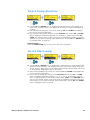
15.3 Calibration
To dispense the correct amount of fluid the pump must know which pumphead is fitted and the tube size in the pumphead. You may also measure the flow from the
pump and enter this value for the most accurate calibration.
Use the UP and DOWN keys to select Calibrate from the main menu. Press
RETURN.
The pump shows the stored values of pumphead, tube size, and present flow
rate in ml per minute. Example figures are shown here.
If the pumphead and tube information is correct, select Accept and press RETURN. The pump briefly displays a summary of the current speed and flow settings, and the main menu.
If the pumphead and tube information is wrong use the UP and DOWN keys to
select Change and press RETURN.
The display lists pumphead options. Use the UP and DOWN keys to select
the correct one and press RETURN.
The display lists the tube sizes. Use the UP and DOWN keys to select the cor
rect size and press RETURN. The display asks the user if he wishes to run a
calibration dose.
Watson-Marlow 323Dz User Manual
26
The display asks the user if he wishes to run a calibration dose. To obtain the
most precise calibration, select Yes. Select No if you wish to use the pre-programmed flow data and return to the main menu via a summary of the current
speed and flow settings. Press RETURN.
If you choose to run a calibration dose, the pump displays its current direction
and rotation speed. You may change pump rotation direction and speed using
the DIRECTION and UP and DOWN keys.
Put a measuring container at the pump outlet. Press START. The pump runs for
4 minutes, displaying an information screen for 15 seconds and a further information screen for the rest of the 4 minutes. You may stop the calibration dose
at any time with the STOP key—but allow the pump to run as long as possible
to obtain the most accurate calibration. A minimum of 15 seconds is recommended.
Measure the quantity of fluid dispensed. The measurements must be in millilitres for calibration and dosing. The pump displays its calculated dose volume,
based on previous calibration data. Use the UP and DOWN keys to adjust this
reading to match the measured volume. Press RETURN. The pump displays the
new head, tube and flow settings, and redisplays the main menu. Example figures are shown here.
It is also possible to re-calibrate the pump during a batch run. (See 15.4 Dose.) Recalibration allows fine tuning of basic calibration.
If a re-calibration differs by more than 25% from the original calibration, the re-calibration value will be ignored. Another full calibration is required to change a dose size
by more than 25%.
Watson-Marlow 323Dz User Manual
27
15.4 Dose
The Dose facility programs the pump to dispense measured volumes of fluid. These
can be individual doses, a batch of doses delivered singly, or a batch of doses delivered at timed intervals. A dose, or batch of doses, can be controlled by the pump, by
pressing the START key, or by pressing an optional remote-control foot or hand
switch or by an external logic signal.
You can start pumping immediately using the settings chosen for the previous batch;
or you can alter one or more of the settings before starting to pump.
To start pumping immediately:
Use the UP and DOWN keys to select Dose from the main menu. Press RETURN. The pump displays the dose size, dosing interval and the number of
doses and waits for the START key to be pressed.
When the START key is pressed, the pump offers the user the opportunity to
prime the pump. To do so, press and hold the START key. The pump operates
continuously at maximum speed until the START key is released.
When priming is complete, or if no priming is required, press RETURN. The
pump displays the dose size and the number of doses and waits for the START
key to be pressed to start the batch.
To alter the batch settings before starting pumping:
Use the UP and DOWN keys to select Dose from the main menu. Press RETURN.
The pump displays the first three of the eight parameters which may be set for
the next dosing session: dose volume, dosing interval and number of doses.
Watson-Marlow 323Dz User Manual
28
The Dose menu occupies three screens.
To move from one screen to subsequent screens, repeatedly press
DOWN. Each item is highlighted in turn until the last item on the
screen is highlighted. A further press on the DOWN key displays the
next screen of the menu, with the first item highlighted.
Follow the reverse procedure using the UP key to move to an item
on a previous screen of the menu.
Make a selection using the UP or DOWN keys and press RETURN to confirm
your choice. The values shown are those set for the last dosing session. As each
parameter of the eight is highlighted, you may accept or change its value.
If it is correct, do nothing. UP and DOWN will highlight the next parameter.
If you wish to change it, press RETURN. Use the UP and DOWN keys to alter
the value. When the value is correct, press RETURN.
At any time during the dose setup sequence described below the user
may press START and the pump displays the priming screen and may be
operated according to the parameters in force. If the next batch requires only the dose size to be changed from the last batch, for example, change it and press START, ignoring the other seven parameters.
In this programming area, pressing STOP while setting up dosing parameters returns the value being changed to its original
setting, allowing the user to start again.
Watson-Marlow 323Dz User Manual
29
15.4.1 Dose volume
Use the UP and DOWN keys to highlight the volume line of the display (the top
line, first screen).
If the dose volume displayed is correct, do nothing. UP and DOWN highlight
the next or previous parameter.
If you wish to change the dose volume, press RETURN and use the UP and
DOWN keys to scroll the display to the required dose volume. Example figures
are shown here. To quickly return to the starting value, press STOP. When the
dose volume is correct, press RETURN. The first screen of the dose menu is redisplayed with the new dose size. If you wish to change other parameters, use
the UP and DOWN keys to highlight each as required.
Note: The dose size must use more than two complete revolutions of the pumphead. To obtain best accuracy the dose size
should use more than five revolutions. Where the dose size
uses less than five revolutions, the pump may warn that a
smaller tube size is required. If you do not change the tube size, the
pump may proceed with your selected dose size but accuracy may be
reduced. If the dose is smaller than the two revolution minimum, the
pump displays a warning and does not allow you to proceed. If you
wish to proceed with the dose size, you must perform a new pump calibration using a smaller tube size. (See 15.3 Calibration).
15.4.2 Dose interval
Use the UP and DOWN keys to highlight the dose interval line of the display
(the second line, first screen). The display shows the previously set time interval between doses in seconds.
Note: If the time is set to zero, the pump waits for a start signal from the
START key, or from an optional external control switch or logic signal, before
proceeding with each dose. If the time interval is greater than zero, the pump
proceeds through the sequence of doses at the programmed time interval.
If the interval displayed is correct, do nothing. UP and DOWN highlight the
next or previous parameter.
If you wish to change the interval between doses, press RETURN and use the
UP and DOWN keys to scroll the display to the required interval. Example figures are shown here. To quickly return to the starting value, press STOP. When
the dose interval is correct, press RETURN. The first screen of the dose menu is
redisplayed with the new dose interval. If you wish to change other parameters,
use the UP and DOWN keys to highlight each as required.
Watson-Marlow 323Dz User Manual
30
15.4.3 Number of doses
Use the UP and DOWN keys to highlight the dose number line of the display
(the third line, first screen). The display shows the previously set number of
doses.
If the number displayed is correct, do nothing. UP and DOWN highlight the
next or previous parameter.
If you wish to change the number of doses, press RETURN and use the UP and
DOWN keys to scroll the display to the required number. Example figures are
shown here. To quickly return to the starting value, press STOP. When the
number is correct, press RETURN. The first screen of the dose menu is redisplayed with the new number of doses. If you wish to change other parameters,
use the UP and DOWN keys to highlight each as required.
Note: If the number of doses is set to 1, the pump waits for a press on START
for each dose, and the display during dosing increments with each dose. If the
number of doses is set to greater than 1, the display decrements with each dose
until it reads zero and the batch is complete
.
15.4.4 Pump speed
Use the UP and DOWN keys to highlight the speed line of the display (the first
line, second screen). The display shows the previously set pump speed.
If the speed displayed is correct, do nothing. UP and DOWN will highlight the
next or previous parameter.
If you wish to change the speed, press RETURN and use the UP and DOWN
keys to scroll the display to the required speed, up to a maximum of 300 rpm
(low-speed model or highspeed model fitted with a 314 pumphead) or 400 rpm
(high-speed model fitted with a 313 pumphead). Example figures are shown
here. To quickly return to the starting value, press STOP. When the speed is
correct, press RETURN. The second screen of the dose menu is redisplayed
with the new pump speed. If you wish to change other parameters, use the UP
and DOWN keys to highlight each as required.
Watson-Marlow 323Dz User Manual
31
15.4.5 Pump direction
Use the UP and DOWN keys to highlight the direction line of the display (the
second line, second screen). The display shows the previously set direction of
rotation.
If the direction displayed is correct, do nothing. UP and DOWN will highlight
the next or previous parameter.
If you wish to change the direction, press RETURN and use the UP or DOWN
keys to highlight the desired direction. An example is shown here. Press RETURN. The second screen of the dose menu is redisplayed with the new pump
direction. If you wish to change other parameters, use the UP and DOWN keys
to highlight each as required.
Alternatively ...
Press the DIRECTION key at any point in the menu sequence.
15.4.6 Start ramp
Use the UP and DOWN keys to highlight the start ramp line of the display (the
third line, second screen). The display shows the start ramp setting of the last
dosing session. When set to ‘0’ the pump starts abruptly at full speed. When set
to ‘5’ the pump accelerates softly to full speed.
If the setting displayed is correct, do nothing. UP and DOWN will highlight the
next or previous parameter.
If you wish to change the setting, press RETURN and use the UP or DOWN
keys to highlight the desired setting: 0, 1, 2, 3, 4 or 5. An example is shown
here. To quickly return to the starting value, press STOP. Press RETURN when
correct. The second screen of the dose menu is redisplayed with the new start
ramp setting. If you wish to change other parameters, use the UP and DOWN
keys to highlight each as required.
Watson-Marlow 323Dz User Manual
32
15.4.7 End ramp
Use the UP and DOWN keys to highlight the end ramp line of the display (the
first line, third screen). The display shows the end ramp setting of the last dosing session. When set to ‘0’ the pump stops abruptly. When set to ‘5’ the pump
decelerates softly to a stop.
If the setting displayed is correct, do nothing. UP and DOWN will highlight the
next or previous parameter.
If you wish to change the setting, press RETURN and use the UP and DOWN
keys to highlight the desired setting: 0, 1, 2, 3, 4 or 5. An example is shown
here. To quickly return to the starting value, press STOP. Press RETURN when
correct. The third screen of the dose menu is redisplayed with the new end
ramp setting. If you wish to change other parameters, use the UP and DOWN
keys to highlight each as required.
15.4.8 Drip
The pump can be set to reverse briefly at the end of each dose to prevent drips.
Use the UP and DOWN keys to highlight the drip line of the display (the second
line, third screen). The display shows the drip setting of the last dosing session:
from 0 to 1.0: zero to one revolution at one-tenth of a revolution intervals.
If the setting displayed is correct, do nothing. UP and DOWN will highlight the
next or previous parameter.
If you wish to change the setting, press RETURN and use the UP and DOWN
keys to increase or decrease drip reversal: zero revolutions to 1 revolution at
0.1 revolution intervals. An example is shown here. To quickly return to the
starting value, press STOP. Press RETURN when correct. The third screen of
the dose menu is redisplayed with the new drip setting. If you wish to change
other parameters, use the UP and DOWN keys to highlight each as required.
Watson-Marlow 323Dz User Manual
33
15.4.9 Proceed
If you wish to begin the dosing session, use the UP or DOWN keys to highlight
Proceed and press RETURN. The pump offers the user the opportunity to
prime the pump. To do so, press and hold the START key. The pump operates
continuously at maximum speed until the START key is released. When priming
is complete, or if no priming is required, press RETURN. The pump displays the
dose size and the number of doses and waits for the START key to be pressed.
If you wish to review or change the parameters for the next batch, press STOP
twice and use the UP and DOWN keys to move back up through the list of parameters.
15.4.10 Single dose dispensing
When START is pressed, the pump performs a dosing batch according to the parameters set.
If the batch is set to perform one dose, as in the example shown here, the pump
stops when that dose has been dispensed and waits for a further press on the START
key. As each dose is dispensed, the display increments, recording the number of
doses dispensed so far.
Note: To dispense a batch of one dose and set the pump to count the doses/batches,
check that the dose interval is set to zero seconds. If an interval is set, the pump will
still dispense batches of one dose, but will not increment its display to show how
many doses/batches have been dispensed.
Watson-Marlow 323Dz User Manual
34
15.4.11 Batch dispensing
If the batch is set to perform more than one dose with a set interval between
doses, the pump operates until all the batch's doses have been dispensed. The display decrements as each dose is dispensed, showing the number of doses still to be
dispensed. During the intervals between doses - 3 seconds in the example shown the time elapsing is counted down to show how much time is left before the next
dose will start.
If the interval is set to zero seconds, the batch can be dispensed in individually
triggered doses by repeated presses on the START key. The display decrements as
each dose is dispensed, showing the number of doses still to be dispensed.
When the batch is complete, the pump displays a screen summarising the batch,
and offering two choices: start the batch again or return to the menu screen,
where batch setting changes can be made.
Use the UP and DOWN keys to highlight Start or Menu and press RETURN.
If you select Start, the pump displays the dose size and the number of doses
and waits for the START key to be pressed to begin a repeat batch.
Alternatively ...
Just press START.
Note: When a batch is repeated, no opportunity is offered to prime the pump. If
you wish to re-prime the pump, return to the main menu and re-enter the dosing
menu as if it were a new batch.
Watson-Marlow 323Dz User Manual
35
If you select Menu, the pump displays the main menu. See 15 Main menu.
Batch pause
You can interrupt a batch at any time by pressing STOP. The pump stops and offers
four choices: Unpause: continue the dose sequence from where it was stopped;
Restart: start the dose or the batch from the beginning; Re-calibrate: re-calibrate
the pump; and Exit: abandon the batch and return to the main menu.
Use the UP and DOWN keys to make a selection. Press RETURN to confirm.
Unpause: If you choose Unpause the pump finishes dispensing the current
dose and completes the batch.
Restart: If you choose Restart the pump displays the number of doses in the
batch and the number which have been completed. It offers two choices: restart
the interrupted dose or restart the batch. Use the UP and DOWN keys to make
a selection. Press RETURN to confirm.
Select Restart dose and the pump re-dispenses the interrupted dose and
resumes the batch where it was interrupted - as in the example shown
above.
Watson-Marlow 323Dz User Manual
36
Select Restart batch to command the pump to display the size and number
of doses in he batch, as in the example above, and wait for the START key
to be pressed to restart the batch.
Re-calibrate: (Note: In this manual, re-calibrate means adjust the full calibration previously performed. It is not possible at this point to perform a
fresh full calibration. To do so return to the main menu. See 15.3 Calibration.) If
you choose re-calibrate you can check a recent dose and adjust the dose size
(within a range of ±25%) for the remainder of the batch.
The display shows the volume of fluid it believes it has dispensed in each dose.
Measure the volume of fluid dispensed in a recent dose.
If the pump's display is correct, press RETURN.
If the pump's display is incorrect, use the UP and DOWN keys to adjust the
volume displayed to match the measured quantity of fluid. Press RETURN to
leave the recalibration sequence.
If the volume adjustment needed is greater than 25%, it is likely that the
original calibration is incorrect. The pump displays a warning and resets to
the original calibration value. You must perform a new pump calibration.
Press RETURN to leave the recalibration sequence.
The pump redisplays the four choices: Unpause; Restart; re-calibrate;
and Exit.
Use the UP and DOWN keys to make a selection. Press RETURN to confirm.
If you choose Unpause or Restart the pump operates as described above,
but using a dose adjusted as a result of any changes you made during the
re-calibration sequence. If you choose Re-calibrate, you can repeat the recalibration. If the pump did not allow recalibration because the adjustment
required was greater than 25%, choose Exit. The pump displays the main
menu, from which you can perform a fresh complete calibration of the pump.
Exit: If you choose Exit, the pump redisplays the main menu.
Watson-Marlow 323Dz User Manual
37
15.5 Remote control
A Watson-Marlow remote control footswitch or
handswitch may be used to start the dose or batch.
The dose will proceed once the switch is pressed. In
an emergency press the STOP key to halt the dose.
The switch should be connected as shown. Or a TTLcompatible logic signal may be applied to pin 8. (Low
0V, High 5V maximum. Ground to pin 9).
Never apply mains voltage to the 25-way D socket. Up to 5V TTL
may be applied across pins 8 and 9, but do not apply voltage
across any other pins. It may result in permanent damage not
covered by warranty.
16 Troubleshooting
If the pump display remains blank when the pump is on, make the following checks:
Check the position of the voltage selector switch at the rear of the pump.
Check the mains power switch at the rear of the pump.
Check that mains power is available to the pump.
Check the fuse in the fuse drawer of the IEC mains power connector at the rear
of the pump.
Check the fuse in the mains power plug if one is present.
If the pump runs but there is little or no flow, make the following checks:
Check
Check
Check
Check
Check
Check
Check
Check
that the tube and rotor are in the pumphead.
that fluid is supplied to the pump.
that the tube is not split or burst.
for any kinks or blockages in the lines.
that any valves in the lines are open.
that the correct wall-thickness tube is being used.
direction of rotation.
that the rotor is not slipping on the drive shaft.
If trouble persists, technical assistance for this product is available from your
distributor or Watson-Marlow Ltd, Falmouth TR11 4RU, United Kingdom.
Watson-Marlow 323Dz User Manual
38
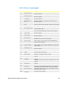
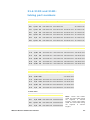
16.1 Error messages
Error
Error condition
Suggested action
0
RAM write error
Attempt to reset by switching power OFF / ON.
Or seek support
1
RAM corruption
Attempt to reset by switching power OFF / ON.
Or seek support
2
OTP ROM error /
corruption
Attempt to reset by switching power OFF / ON.
Or seek support
3
OTP ROM read
error
Attempt to reset by switching power OFF / ON.
Or seek support
5
Unknown pump
type
Check the interface card and cables. Attempt to
reset by switching power OFF / ON. Or seek support
7
Display failure
Seek support
8
Wrong key-press
9
Motor stalled
10
Tacho fault
14
Over speed
Stop pump immediately. Power OFF/ON may reset.
Or seek support
15
Over current
Stop pump immediately. Check system. Power
OFF/ON may reset. Or seek support
16
Over voltage
Stop pump immediately. Check mains voltage selector switch. Check supply. Power OFF/ON may
reset. Or seek support
17
Under voltage
Stop pump immediately. Check mains voltage selector switch. Check supply. ON/OFF may reset. Or
seek support
18
Watchdog error
Attempt to reset by switching power OFF / ON.
Or seek support
19
Over temperature
Stop pump immediately. Turn OFF. Seek support
20
Signal out of
range
Check analogue control signal range. Trim signal as
required. Or seek support
21
Over signal
Reduce the analogue control signal
22
No signal
25
Network not
detected
26
RS232 fault
27
RS232 lost
33
Unrecognised
keypress
35
Work overload
ERR
General error
condition
Watson-Marlow 323Dz User Manual
Attempt key-press again. Attempt to reset by
switching OFF / ON
Stop pump immediately. Check pumphead and
tube. Power OFF/ON may reset. Or seek support
Stop pump immediately. Power OFF/ON may reset.
Or seek support
Connect analogue control signal or return to manual
control
Turn OFF. Check network and connections. Or seek
support
Turn OFF. Check network and connections. Or seek
support
Turn OFF. Check network and connections. Or seek
support
Attempt keypress again. Attempt to reset by
switching power OFF/ON. Otherwise seek support.
Turn OFF. Check power supply. Check pumphead
and tubing. Wait 30 minutes. Power ON may reset.
Otherwise seek support.
Turn OFF. Seek support
39
17 Drive maintenance
The pump is sealed to IP31 and is suitable for wipe-down cleaning. Do not use solvents, mechanical scourers, strong organic acids, or alkali-based cleaning solutions.
Remove any tubing, detach the pumphead, and wash the pumphead thoroughly with
a mild solution of detergent in water.
Check moving parts of the rotor from time to time for freedom of movement. Lubricate pivot points and rollers occasionally with Teflon lubricating oil.
The pump has a good, broad chemical resistance to inorganic acids, saline solutions,
alkalis, some hydrocarbons and a large number of oils and greases. It is suitable for
wipe-down but not for long-term contact with alcohols. The case may be damaged by
contact with strong acids or strong solvents.
There are no user serviceable parts inside the pump. The unit should be returned to Watson-Marlow or its appointed agents or distributors for
service.
18 Drive part numbers
Drives only
Part number
Drive type
Drive speed
Pumphead
036.3183.00U
036.3184.00U
323Dz
323Dz
300
400
-
Mains lead
type
UK
UK
Complete pump assemblies
Part number
Drive type
Drive speed
Pumphead
030.3183.RLU
030.3184.3DU
030.3184.4DU
323Dz
323Dz
32Dz
300
400
400
501RL
313D
314D
Mains lead
type
UK
UK
UK
For US mains lead, replace ‘U’ with ‘A’ at end of part number.
For European mains lead, replace ‘U’ with ‘E’.
U
Watson-Marlow 323Dz User Manual
E
A
40
19 Drive spares
Spare
Description
1
MN2094T
Interface card cover
2
FB0009
Foot
3
FS0003
Fuse
20 Accessories
520AF
Footswitch
059.3002.000
520AH
Handswitch
059.3022.000
505AS
Filling stand
059.5001.000
505AL
Dispensing lance
059.5052.000
Watson-Marlow 323Dz User Manual
41
21 Pumpheads
21.1 Pumpheads: key safety information
Before opening the pumphead track please
ensure that the following safety directions are
followed.
Ensure that the pump is isolated from mains voltage.
Ensure that there is no pressure in the pipeline.
If a tube failure has occurred, ensure that any product in the pumphead has
been allowed to drain to a suitable drain.
Ensure that protective clothing and eye protection are worn if hazardous products are being pumped.
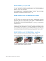
21.2 313D and 314D pumpheads
314D pumpheads should run no faster than 300 rpm
when in continuous use. Speeds up to 400 rpm are permissible for intermittent use.
The 313D pumphead has three rollers and is designed to provide higher flow rates.
The 314D pumphead has four rollers to provide greater pumping precision with less
pulsation in the flow. Both designs are available for 1.6mm and 2.4mm wall tubes.
New tubing can be loaded easily into the flip top design. The top closes with a “clamp
and stretch” action to locate the tube in the correct position and with the correct tension.
Standard and extension pumpheads are bayonet mounted. This ensures easy cleaning and fast set up.
Tube selection
The chemical compatibility list published in the Watson-Marlow web site is only a
guide. If in doubt request a tube sample card for immersion trials.
Watson-Marlow 323Dz User Manual
42
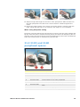
Installation
323 400 rpm drives (shown) have an integral mounting plate to attach a 313 or 314
pumphead.
Engage the pumphead drive slot with the end of the pump drive shaft. Continue to
align the pumphead until the bayonet engages with the mounting plate. Turn the
pumphead clockwise until it locks into an upright position.
Removal
Push the locking lever back and turn the pumphead anti-clockwise until it is free from
the mounting plate.
Tube loading
Switch off the pump before tube loading. Lift the “flip top” track until fully open.
Set the tube clamps to the correct
tube size. The track must be fully
open. Align the scale on both sides of
the pumphead.
If the tube is dirty, or there is a high suction lift, the tube clamps may need a smaller
setting to secure the tube.
Watson-Marlow 323Dz User Manual
43
Select enough tube length for the curve of the pump track. Slide the tube into
the open pumphead. The tube must not be twisted or stretched against the
rollers.
Ensure the tubing locates in the centre of the tube clamps. Carefully lower the
track. Check that the tube is not crushed in the clamps or over stretched.
When using Marprene tubing
Re-tension new tube after the first 30 minutes of running. Stop the pump. Release the
flip top. Allow the tube to resettle naturally across the rollers. Re-clamp the tube. Restart the pump. This will correct the normal stretching that occurs with new Marprene
tube. The correct tension is essential for good tube life.
21.3 313D and 314D
pumphead spares
Spare
Description
1
033.3411.000
313D three-roller pumphead
2
033.3431.000
313X extension three-roller pumphead
1
033.4411.000
314D four-roller pumphead
2
033.4431.000
314X extension four-roller pumphead
1
033.3511.000
313D2 three-roller pumphead for 2.4mm tube
2
033.3531.000
313X2 extension three-roller pumphead for 2.4mm
tube
1
033.4511.000
314D2 four-roller pumphead for 2.4mm tube
2
033.4531.000
314X2 extension four-roller pumphead for 2.4mm tube
Watson-Marlow 323Dz User Manual
44
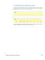
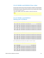
21.4 313D and 314D flow rates
Flow rates were obtained using silicone tubing with the pumphead rotating clockwise,
pumping water at 20°C with zero suction and delivery pressures. For critical applications determine flow rates under operating conditions.
Flow rates, 313D, 1.6mm wall (ml/min)
bore
mm
0.5
0.8
1.6
3.2
4.8
6.4
8.0
in
1/50
1/32
1/16
1/8
3/16
1/14
5/16
112
13
14
16
25
17
18
#
2-400 rpm
0.06-12 0.14-28 0.54-110
2-400
404-880 7.2-1400 10-2000
Flow rates, 314D, 1.6mm wall (ml/min)
bore
mm
0.5
0.8
1.6
3.2
4.8
6.4
8.0
in
1/50
1/32
1/16
1/8
3/16
1/14
5/16
112
13
14
16
25
17
18
#
2-400 rpm
0.06-12 0.12-24 0.50-100 1.7-340 3.8-760 6.0-1200 8.0-1600
Note: 314D pumpheads should run no faster than 300 rpm when in continuous use.
Speeds up to 400 rpm are permissible for intermittent use.
Watson-Marlow 323Dz User Manual
45
21.5 313D and 314D: maximum number
of pumpheads
313D, 314D Pumpsil, to 400 rpm
mm
0.5
0.8
1.6
3.2
4.8
6.4
8.0
in
1/50
1/32
1/16
1/8
3/16
1/14
5/16
112
13
14
16
25
17
18
0-0.5 bar
6
6
5
3
2
2
1
0.5-2 bar
6
6
5
3
2
1
1
bore
#
313D, 314D Marprene, Bioprene, Tygon, Neoprene, Fluorel, to 400 rpm
bore
mm
0.5
0.8
1.6
3.2
4.8
6.4
8.0
in
1/50
1/32
1/16
1/8
3/16
1/14
5/16
112
13
14
16
25
17
18
6
6
4
2
2
1
1
#
0-2 bar
313D, 314D STA-PURE, CHEM-SURE, to 400 rpm
bore
mm
1.6
3.2
4.8
6.4
8.0
in
1/16
1/8
3/16
1/14
5/16
14
16
25
17
18
1
1
1
1
1
#
0-2 bar
313D2, 314D2 Pumpsil, Marprene, Bioprene, Tygon, Neoprene, Fluorel,
STA-PURE, CHEM-SURE, to 400 rpm
bore
mm
0.5
0.8
1.6
3.2
4.8
6.4
8.0
in
1/50
1/32
1/16
1/8
3/16
1/14
5/16
112
13
14
16
25
17
18
1
1
1
1
1
1
1
#
0-2 bar
Note: 314D pumpheads should run no faster than 300 rpm when in continuous use.
Speeds up to 400 rpm are permissible for intermittent use.
Watson-Marlow 323Dz User Manual
46
21.6 313D and 314D:
tubing part numbers
1.6mm tube
mm
in
#
Marprene
Bioprene
CHEM-SURE
Pumpsil
0.5
1/50 112 902.0005.016 903.0005.016
913.A005.016
0.8
1/32
13
902.0008.016 903.0008.016
913.A008.016
1.6
1/16
14
902.0016.016 903.0016.016 965.0016.016 913.A016.016
3.2
1/8
16
902.0032.016 903.0032.016 965.0032.016 913.A032.016
4.8
3/16
25
902.0048.016 903.0048.016 965.0048.016 913.A048.016
6.4
1/4
17
902.0064.016 903.0064.016 965.0064.016 913.A064.016
8.0
5/16
18
902.0080.016 903.0080.016 965.0080.016 913.A080.016
1.6mm tube
mm
in
#
PVC
Fluorel
Neoprene
STA-PURE
0.8
1/32
13
1.6
1/16
14
950.0016.016 970.0016.016 920.0016.016 960.A016.016
3.2
1/8
16
950.0032.016 970.0032.016 920.0032.016 960.A032.016
4.8
3/16
25
950.0048.016 970.0048.016 920.0048.016 960.A048.016
6.4
1/4
17
950.0064.016 970.0064.016 920.0064.016 960.A064.016
8.0
5/16
18
950.0080.016 970.0080.016 920.0080.016 960.A080.016
920.0008.016
2.4mm tube
mm
in
#
Marprene
Bioprene
Pumpsil
0.5
1/50 105
913.0005.024
0.8
1/32 108
913.0008.024
1.6
1/16 119 902.0016.024 903.0016.024 913.0016.024
3.2
1/8
120 902.0032.024 903.0032.024 913.0032.024
4.8
3/16
15
902.0048.024 903.0048.024 913.0048.024
6.4
1/4
24
902.0064.024 903.0064.024 913.0064.024
#
CHEM-SURE
2.4mm tube
mm
1.6
in
STA-PURE
1/16 119 965.0016.024 960.0016.024
3.2
1/8
120 965.0032.024 960.0032.024
4.8
3/16
15
965.0048.024 960.0048.024
6.4
1/4
24
965.0064.024 960.0064.024
Watson-Marlow 323Dz User Manual
Note: 1.6mm wall CHEMSURE and STA-PURE tubing
are supplied in 305mm
lengths. 2.4mm wall CHEMSURE and STA-PURE tubing
are supplied in 355mm
lengths.
47
21.7 501RL pumphead
The 501RL and 501RL2 pumpheads are suitable for tubing with internal diameters up
to 8.0mm. The 501RL is set during manufacture for use with 1.6mm wall tubing and
501RL2 is set for 2.4mm wall tubing.
The spring-loaded rollers give extended tube life. The pumphead can be run clockwise, for best tube life, or anticlockwise for higher pressures. The “tool lockable”
guard should be locked shut while the pump is in use.
21.8 501RL and 501RL2 installation
The 501RL track will fit on the drive in three orientations. Secure the track with the
locating screw.
The rotor grips the drive shaft via a split collet. Ensure the drive shaft is degreased
before fitting the rotor. This will prevent the rotor slipping on the drive shaft during
operation. Tighten the rotor screw to a torque of 3Nm.
The track and rotor may be removed from the pump for cleaning or to reposition the
track on the pump.
There is a drive pin inside the rotor collet to engage with the end of the drive shaft.
To keep this pin correctly engaged on the drive shaft, we recommend that the collet
remains on the shaft, while the rotor is removed. Hold the rotor firmly and remove
the rotor retaining screw. Pull the rotor from the drive shaft leaving the collet on the
drive shaft. Remove the track locating screw. You may remove the track or rotate to
the new position. Align the track and refit the track locating screw. Refit the rotor.
21.9 501RL and 501RL2 tube loading
Switch off the mains supply. Unlock and open the pumphead guard.
Select a minimum length of 240mm of tubing. Fit one end of the tubing into a clamp.
The rotor has tube guide rollers that pull the tube into the pumphead during loading.
Turn the rotor carefully until the tube guides pick up the tube. Continue to turn the
rotor, and feed the tubing in between the guides.
Watson-Marlow 323Dz User Manual
48
When the tube has gone round the pump track fit the other end of the tubing into the
clamp. Check that the tubing has fitted naturally against the track for best tube life.
Release the clamps and adjust the tubing if it is slack, twisted, or stretched.
The tube clamps can accommodate various tube diameters by pushing in, or pulling
out, the grip bars within the clamp. Set the clamps to apply the minimum necessary
pressure to the tubing.
Restart the pump. Free the downstream clamp for a short time, while the pump is
running, so that the tube can find its natural length. Please keep fingers clear of the
moving rotor. Shut and lock the guard after adjusting the tube.
When using Marprene tubing
Re-tension new tube after the first 30 minutes of running. Stop the pump and release
the tube clamp at the outlet of the pump. Pull any slack tube from the pumphead and
re-clamp the tube. Re-start the pump. This will correct the normal stretching that occurs with new Marprene tube. The correct tension is essential for good tube life.
21.10 501RL and 501RL2 rotor settings
The 501RL and 501RL2 pumpheads are factory set to give optimum tube life with
Watson-Marlow tubing. We recommend that the rotors are not adjusted or that other
types of tubing are not used.
If the rotor needs re-aligning we recommend the rotor is returned to Watson-Marlow
for correct adjustment. Or contact our technical department for further information.
Check moving parts of the rotor from time to time for freedom of movement. Lubricate pivot points and rollers occasionally with Teflon lubricating oil.
Watson-Marlow 323Dz User Manual
49
21.11 501RL and 501RL2
pumphead spares
Spare
Description
053.0001.L00
501RL complete pumphead
053.0001.L20
501RL2 complete pumphead
1
SG001
SG002
Springs for 501RL (blue)
Springs for 501RL2 (red)
2
MN0012T
Follower roller
3
MN0011T
Main roller
4
MNA0143A
5
CL0656T
Collet
6
FN4502
Lock
7
MN0377M
Lockable guard
8
MN0266M
Hinge
9
FN2341
10
MNA0114A
501RL rotor assembly
Hinge screw
Tube clamp assembly
11
FN2332
Screw
-
XX0095
Teflon lubricant
Watson-Marlow 323Dz User Manual
50
21.12 501RL and 501RL2 flow rates
Flow rates were obtained using silicone tubing with the pumphead rotating clockwise,
pumping water at 20°C with zero suction and delivery pressures. For critical applications determine flow rates under operating conditions. The important factors are suction and delivery pressure, temperature and fluid viscosity. Tube life will be reduced
when pumping against pressure.
Flow rates, 501RL, 1.6mm wall, 501RL2, 2.4mm wall (ml/min)
bore
mm
0.5
0.8
1.6
3.2
4.8
6.4
8.0
in
1/50
1/32
1/16
1/8
3/16
1/14
5/16
#
1-300 rpm
112
0.04-13
13
14
16
25
17
18
0.12-37 0.43-130 1.9-560 4.0-1200 6.4-1900 10-3000
21.13 501RL and 501RL2:
tubing part numbers
1.6mm tube for 501RL pumpheads
mm
in
#
Marprene
Bioprene
CHEM-SURE
Pumpsil
0.5
1/50 112 902.0005.016 903.0005.016
913.A005.016
0.8
1/32
13
902.0008.016 903.0008.016
913.A008.016
1.6
1/16
14
902.0016.016 903.0016.016 965.0016.016 913.A016.016
3.2
1/8
16
902.0032.016 903.0032.016 965.0032.016 913.A032.016
4.8
3/16
25
902.0048.016 903.0048.016 965.0048.016 913.A048.016
6.4
1/4
17
902.0064.016 903.0064.016 965.0064.016 913.A064.016
8.0
5/16
18
902.0080.016 903.0080.016 965.0080.016 913.A080.016
1.6mm tube for 501RL pumpheads
mm
in
#
PVC
Fluorel
Neoprene
STA-PURE
0.8
1/32
13
920.0008.016
1.6
1/16
14
950.0016.016 970.0016.016 920.0016.016 960.0016.016
3.2
1/8
16
950.0032.016 970.0032.016 920.0032.016 960.0032.016
4.8
3/16
25
950.0048.016 970.0048.016 920.0048.016 960.0048.016
6.4
1/4
17
950.0064.016 970.0064.016 920.0064.016 960.0064.016
8.0
5/16
18
950.0080.016 970.0080.016 920.0080.016 960.0080.016
Note: CHEM-SURE and STA-PURE are supplied in 305mm lengths.
2.4mm tube for 501RL2 pumpheads
mm
in
#
Marprene
Bioprene
Pumpsil
0.5
1/50 105
913.A005.024
0.8
1/32 108
913.A008.024
1.6
1/16 119 902.0016.024 903.0016.024 913.A016.024
3.2
1/8
4.8
3/16
15
902.0048.024 903.0048.024 913.A048.024
6.4
1/4
24
902.0064.024 903.0064.024 913.A064.024
8.0
120 902.0032.024 903.0032.024 913.A032.024
5/16 121 902.0080.024 903.0080.024 913.A080.024
Watson-Marlow 323Dz User Manual
51
22 Trademarks
Watson-Marlow, Bioprene, Pumpsil and Marprene are trademarks of Watson-Marlow
Limited.
Fluorel is a trademark of 3M.
Sta-Pure and Chem-Sure are trademarks of W.L.Gore and Associates.
23 Warning not to use pumps in
patient-connected applications
Warning: These products are not designed for use in, and should not be used for patient-connected applications.
24 Publication history
m-323dz-gb-04.qxp: Watson-Marlow 323Dz.
First published 01 02. Revised 01 08.
Watson-Marlow 323Dz User Manual
52
25 Decontamination certificate
In compliance with the UK Health and Safety at Work Act and the Control of Substances Hazardous to Health Regulations, you are required to declare the substances
which have been in contact with product(s) you return to Watson-Marlow or its subsidiaries or distributors. Failure to do so will cause delays. Please ensure that you fax
us this form and receive an RGA (Returned Goods Authorisation) before you despatch
the product(s). A copy of this form must be attached to the outside of the packaging
containing the product(s). Please complete a separate decontamination certificate for
each product. You are responsible for cleaning and decontaminating the product(s)
before return.
Your name
Company
Address
Postcode/zip
Country
Telephone
Fax
Product type
Serial number
To speed the
repair, please
describe all
known faults
The product has ...
I
Been used
I
Not been used
If the product has been used, please complete all the following sections.
If the product has not been used, please just sign this form.
Names of
chemicals handled
with product(s)
Precautions to be
taken in handling
these chemicals
Action to be taken
in the event of
human contact
I understand that the personal data collected will be kept confidentially
in accordance with the UK Data Protection Act 1998.
RGA number
Signature
Your position
Date
Please print out, sign and fax to Watson-Marlow Pumps at +44 1326 376009.
Watson-Marlow 323Dz User Manual
53