1
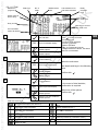
dynafor
™
Series LLXh Electronic Dynamometer
dinamómetro electrónico serie LLXh
dinamometro elettronico serie LLXh
dinamómetro electrónico série LLXh
English
Español
Italiano
Português
15 / 25 / 50 / 100 / 250 t
GB
Operation and maintenance
manual
IT
Istruzioni per l’uso e la
manutenzione
E
Instrucciones de utilización
y de mantenimiento
P
Instruções de uso e de
manutenção
®
®
2
TABLE OF CONTENTS
page
PRIORITY RECOMMENDATIONS • • • • • • • • • • • • • • • • • • • • • • • • • • • • • • • • • • • • • 4
GB
1. PRESENTATION • • • • • • • • • • • • • • • • • • • • • • • • • • • • • • • • • • • • • • • • • • • • • • •
1.1. Operating Principle • • • • • • • • • • • • • • • • • • • • • • • • • • • • • • • • • • • • • •
1.2. Description and marking • • • • • • • • • • • • • • • • • • • • • • • • • • • • • • • • • •
1.2.1. Sensor • • • • • • • • • • • • • • • • • • • • • • • • • • • • • • • • • • • • • • •
1.2.2. Display unit • • • • • • • • • • • • • • • • • • • • • • • • • • • • • • • • • • • •
5
5
6
6
7
2. SPECIFICATIONS • • • • • • • • • • • • • • • • • • • • • • • • • • • • • • • • • • • • • • • • • • • • • •
2.1. Sensor and Display Unit • • • • • • • • • • • • • • • • • • • • • • • • • • • • • • • • • •
2.2 Anchoring accessory • • • • • • • • • • • • • • • • • • • • • • • • • • • • • • • • • • • • • •
2.2.1 Size • • • • • • • • • • • • • • • • • • • • • • • • • • • • • • • • • • • • • • • • •
8
8
9
9
3. INSTALLATION, UTILIZATION AND UNINSTALLATION
4. UTILIZATION PROHIBITIONS
• • • • • • • • • • • • • • • • • 9,10
• • • • • • • • • • • • • • • • • • • • • • • • • • • • • • • • • • • • • 10
5. OVERLOAD INDICATOR • • • • • • • • • • • • • • • • • • • • • • • • • • • • • • • • • • • • • • • • • 10
6. OPERATION IN SINGLE CONFIGURATION • • • • • • • • • • • • • • • • • • • • • • • • • • • 11
6.1. Commissioning • • • • • • • • • • • • • • • • • • • • • • • • • • • • • • • • • • • • • • • • 11
6.1.1. Enabling the sensor batteries • • • • • • • • • • • • • • • • • • • • • • • 11
6.1.2. Charging the display unit • • • • • • • • • • • • • • • • • • • • • • • • • • 11
6.1.3. Turning on the sensor • • • • • • • • • • • • • • • • • • • • • • • • • • • • 11
6.1.4. Information provided by the sensor LED • • • • • • • • • • • • • • • 11
6.1.5. Turning on the display unit • • • • • • • • • • • • • • • • • • • • • • • • • 12
6.2. Elementary functions • • • • • • • • • • • • • • • • • • • • • • • • • • • • • • • • • • • • 12
6.2.1. Standard display screen • • • • • • • • • • • • • • • • • • • • • • • • • • 12
6.2.2. Detailed description • • • • • • • • • • • • • • • • • • • • • • • • • • • • • 13
6.2.3. Icons • • • • • • • • • • • • • • • • • • • • • • • • • • • • • • • • • • • • • • • • 13
6.2.4. Elementary functions and corresponding displays • • • • • • • • • 14
6.2.4.1. Standard display • • • • • • • • • • • • • • • • • • • • • • • • 14
6.2.4.2. Navigating between icons • • • • • • • • • • • • • • • • • • 14
6.2.4.3. Measurement unit selection • • • • • • • • • • • • • • • • 14
6.2.4.4. Tare Function • • • • • • • • • • • • • • • • • • • • • • • • • • 14
6.2.4.5. MAX Function ( Peak stress save ) • • • • • • • • • • • 15
6.2.4.6. Language selection function • • • • • • • • • • • • • • • • 16
6.2.4.7. Stopping the device • • • • • • • • • • • • • • • • • • • • • • 17
6.2.5. Error Messages • • • • • • • • • • • • • • • • • • • • • • • • • • • • • • • • 17
6.3. Advanced functions • • • • • • • • • • • • • • • • • • • • • • • • • • • • • • • • • • • • • 17
6.3.1. Main Menu • • • • • • • • • • • • • • • • • • • • • • • • • • • • • • • • • • • 17
6.3.1.1. Functions Menu • • • • • • • • • • • • • • • • • • • • • • • • • 17
The functions described hereinafter enable standard use of the dynafor™LLXh
The possibilities offered by dynafor™ LLXh extend well beyond these elementary functions, and
respond to the wide range of requirements encountered in industry .
To name but a few: display of several sensors on the same display unit, display of the stress
on one or more sensors on several display units, PC link-up, saving, totalling, dif ferentiation,
threshold management etc… all of these functions are described further on in this manual.
2
6.3.1.1.1. Save • • • • • • • • • • • • • • • • • • 18
6.3.1.1.2. Total • • • • • • • • • • • • • • • • • • 19
6.3.1.1.3. Threshold Management • • • • • 20
6.3.1.2. Parameter setting menu • • • • • • • • • • • • • • • • • • • 21
6.3.1.2.1. Date and Time • • • • • • • • • • • 21
6.3.1.2.2. Coefficients • • • • • • • • • • • • • 21
6.3.1.2.3. Available memory check • • • • 21
6.3.1.3. Languages • • • • • • • • • • • • • • • • • • • • • • • • • • • • 21
6.3.2. Other icons on the standard screen • • • • • • • • • • • • • • • • • • 22
6.3.2.1. Sensor settings and data • • • • • • • • • • • • • • • • • • 22
6.3.2.2. Display Unit Settings and Data • • • • • • • • • • • • • • 22
6.3.2.3. Display unit and sensor identification and data • • • • 22
6.3.2.4. Data on the power and status of the radio link • • • • 23
7. OPERATION IN MULTIPLE CONFIGURATION • • • • • • • • • • • • • • • • • • • • • • • • • 23
7.1. Generalities • • • • • • • • • • • • • • • • • • • • • • • • • • • • • • • • • • • • • • • • • • • 23
7.2. Examples of multiple configurations • • • • • • • • • • • • • • • • • • • • • • • • • • 24
7.3. Safety Recommendations • • • • • • • • • • • • • • • • • • • • • • • • • • • • • • • • • 24
7.4. General procedure for setting up multiple configurations • • • • • • • • • • • • 25
7.5. Tools for setting up multiple configurations • • • • • • • • • • • • • • • • • • • • • 26
7.5.1. Unlocking an assembly • • • • • • • • • • • • • • • • • • • • • • • • • • • 26
7.5.2. Locking an assembly • • • • • • • • • • • • • • • • • • • • • • • • • • • • • 26
7.5.3. Associating an assembly • • • • • • • • • • • • • • • • • • • • • • • • • • 27
7.5.4. Setting display unit parameters in Master and Slave mode • • • 27
7.5.5. Radio channel availability • • • • • • • • • • • • • • • • • • • • • • • • • 28
7.5.6. Changing the radio channel • • • • • • • • • • • • • • • • • • • • • • • • 28
7.5.7. Association of components • • • • • • • • • • • • • • • • • • • • • • • • • 29
7.5.7.1. Adding one or more sensors a) & b) • • • • • • • • • • • 29
7.5.7.2. Adding a Slave display unit a) & b) • • • • • • • • • 30, 31
7.6. Display in multiple configuration • • • • • • • • • • • • • • • • • • • • • • • • • • • • • 32
7.6.1. Multiple Display menu • • • • • • • • • • • • • • • • • • • • • • • • • • • • • 32
8. PC CONNECTION (OPTIONAL ) • • • • • • • • • • • • • • • • • • • • • • • • • • • • • • • • • • • • 33
8.1. Description
• • • • • • • • • • • • • • • • • • • • • • • • • • • • • • • • • • • • • • • • • • 33
9. MAINTENANCE, CHECKING AND CLEANING • • • • • • • • • • • • • • • • • • • • • • • • • •
9.1. Battery and power pack status • • • • • • • • • • • • • • • • • • • • • • • • • • • • • •
9.2. Changing sensor batteries • • • • • • • • • • • • • • • • • • • • • • • • • • • • • • • • •
9.3. Regulatory check • • • • • • • • • • • • • • • • • • • • • • • • • • • • • • • • • • • • • • •
9.3.1. Certificate of Adjustment • • • • • • • • • • • • • • • • • • • • • • • • • • •
9.3.2. ISO 376 calibration certificate • • • • • • • • • • • • • • • • • • • • • • •
9.4. Maintenance • • • • • • • • • • • • • • • • • • • • • • • • • • • • • • • • • • • • • • • • • • •
33
33
33
33
33
33
33
10. STORAGE, TRANSPORT, DISPOSAL • • • • • • • • • • • • • • • • • • • • • • • • • • • • • • • 34
11. OPERATING ANOMALIES AND TROUBLESHOOTING
• • • • • • • • • • • • • • • • 34, 35
12. PRODUCT MARKING • • • • • • • • • • • • • • • • • • • • • • • • • • • • • • • • • • • • • • • • • • 35
3
GB
PRIORITY RECOMMENDATIONS
CAUTION. Possible situation. Hazardous. Risk of slight injury or damage of the appliance.
Appliance completely protected by double or reinforced insulation.
1. Before installing and using this unit, to ensure safe, efficient use of the unit, be sure you have read and fully understood the information and instructions given in this manual. A copy of this manual should be made
available to
every operator. Extra copies of this manual can be supplied on request.
GB
2. Do not use the unit if any of the plates mounted on the unit are missing or if any of the information on the plates, as
indicated at the end of the manual, are no longer legible. Identical plates will be supplied on request; these must be
secured on the unit before it can be used again.
3. Make sure that all persons operating this unit know perfectly how to use it in a safe way , in observance of all safety
at work regulations. This manual must be made available to all users.
4. The positioning and commissioning of this appliance must be carried out under conditions that ensure installer safety
in compliance with the relevant regulations.
5. Each time, before using the unit, inspect the unit for any visible damage, as well as the accessories used with the
unit. Never use an appliance that is not obviously in good condition. Return the appliance to the manufacturer for
servicing if any anomalies arise that have no connection with the state of the battery .
6. Protect your appliance from any form of impact, especially the display unit.
7. The unit must never be used for any operations other than those described in this manual. The unit must never be
used to handle any loads exceeding the maximum utilization load indicated on the unit. It must never be used in
explosive atmospheres.
8. This appliance should never be used for man-riding applications without a thorough prior check that the utilization
coefficients required for personnel safety have been applied, and more generally that the safety regulations for the
load line on which it has been installed have been applied.
9. Tractel declines any responsibility for use of this unit in a setup configuration not described in this manual.
10. Tractel declines any responsibility for the consequences of any changes made to the unit or removal of parts.
11. Tractel declines any responsibility for the consequences resulting from disassembly of the unit in any way not described in this manual or repairs performed without Tractel authorization, especially as concerns replacement of original parts by parts of another manufacturer .
12. As a dynafor™ dynamometer is a lifting accessory , the safety regulations applicable to this category of equipment
must be applied.
13. If the unit is to be definitively removed from use, make sure the unit is discarded in a way which will prevent any
possible use of the unit. All environment protection regulations must be observed.
14. Any operation of this appliance in conjunction with supplementary equipment relaying signals on an operating system must be preceded by a risk analysis related to the operating functions implemented, carried out by the system
user or assembler, and all appropriate measures are taken as a consequence.
15. Certified in compliance with European regulations, this appliance should be checked for compliance with the regulations of any other country where it might be used, prior to being commissioned there.
16. The display power supply unit is used as a breaker and must be accessible at any time.
4
1 PRESENTATION
The dynafor™ LLXh dynamometers are precision appliances (0.2% ISO 376 . 21°C), for measuring pulling force and indicating loads. The capacity scale ranges from 150 kN to 2500 kN.
A dynafor™ LLXh is made up of a sensor and a mobile display unit.
A two-way radio link-up using the 2.4 GHz wave band conects the two components.
16 radio channels are used. Each display unit and sensor have their own address, enabling unequivocal
identification in the event of a multiple set-up.
The shape of the dynamometers enable the use of standard shackles on both ends.
The technologies implemented on a radio and software level of fer, aside from the standard uses to be
expected from an industrial dynamometer , multiple configuration possibilities that combine several
sensors with several display units. They also of fer access to advanced function such as: saving,
threshold management, monitoring etc.
The PC – USB link permits to dowload, save and manage measurements data.
The standard version of the equipment comes with batteries and power pack in a plastic carrying case for
capacities up to 50 t and wood case for 100 t and 250 t.
a) A sensor
b) A display unit and battery charger
c) An operating and maintenance instruction manual
d) A certificate of adjustment
e) A certificate of CE compliance
1.1 Operating Principle
The operating principle of the dynafor ™ LLXh is based on strain gauge measurement of the extension,
within its limits of elasticity, of a metal body subjected to traction stress.
The appliance will work in all directions.
The sensor generates an electrical signal that is proportional to the load. This signal is processed by a
micro-processor analyser and then transmitted via radio waves to the display unit, which immediately
displays the load applied to the sensor to which it is linked.
When switched on, the sensor data, such as identification and date of last metrology check, is displayed
on the display unit.
The display unit is compatible with all of the LLXh model sensors, irrespective of their capacity . Unless
otherwise ordered, the radio link-up between the LLXh and LLX2 sensor and the display unit is set definitively in the factory before dispatch. After this, the radio link can be configured by the user to meet their
requirements.
5
GB
1.2 Description and marking
1.2.1 Sensor
A
E
K
I
GB
B
F
C
G
L
J
D
M
H
A
Centering ring
H
Serial N°.
B
Front plate
I
Rear plate
C
Operating indicator
J
Fixing screw of L
D
Maximum sensor capacity
K
Battery housing (3 x “AA”)
E
Body
L
Battery cover
F
Designation and accuracy
M
Manufacturer’s label
G
On / Off button
Provisions applied:
- Machine Directives: 98/37/CEE
- European Standards: EN 12100-1 and 12100-2
- CEM Directive: 89/336/CEE
- Electrical Safety: IEC 61010-1 2 nd Edition
- Radio certifications: CE : Radio Tests EN 300 440-2 V1.1.1 / USA & Canada:
FCC ID / Australia: C-Tick ID
- R&TTE Directive (1999/5/CE)
6
1.2.2 Display unit
o
a
b
e
c
f
g
d
GB
h
i
j
k
l
m
n
o
p
a
Indicator LED ( manufacturer use )
i
LCD graphic screen
128 x 64 pixels 67 x 40 mm
b
Key: "esc"
j
Attaching points for the display unit on
the bumper of the sensor housing
c
Key: Back lighting. Auto off after 10"
k
CE Marking and Serial No.
d
Key: On / Off
l
Charger socket
e
Key: Enables available options and
clockwise browsing
m
Serial port ( manufacturer use )
f
Key: Enables available options and
anti-clockwise browsing
n
USB port
g
Key: Confirm / Enter
o
Metal wire
h
Safety wrist strap
p
Charger 100-240 Vac 50/60 Hz. 180 mA
Secondary: 12 Vdc. 500 mA.
7
2. SPECIFICATIONS
2.1 Sensor and Display Unit
C
j
A B
GB
i
h
F
E
D
t
t
LLXh
15 t
15
30
daN
daN
30
5
MODEL
Maximum capacity
Test load
Safety coefficient
Precision
Increment
Max. Display
Number height
Autonomy
Radio scope
RF technology
Weight
IP Protection
Usafe
Sensitivity to T°
Sensor material
Dimensions mm
LLXh
25 t
25
50
LLXh
LLXh
LLXh
50 t
100 t
250 t
50
100
250
100
200
500
Minimum 4
0,2 % according to ISO 376 . 21°C
50
100
200
500
10
20
50
100
16500 daN 27500 daN 55000 daN
mm
m
kg
A
B
ØC
D
E
F
h
i
j
110.00 t
275.00 t
From 300 to 1000 h depending of functions
80 (in open field) (I.P. 67 = 60)
2.4 Ghz
4
6.6
15.1
46
215
I.P. 65 (I.P. 67 option)
From - 20° to 40°C
0.05% per 10°C
Aluminium
320
360
440
660
905
247.5
277
338
488
685
47.5
56
72
108
150
130
134
164
260
424
58
68
98
118
248
48
58
86
104
190
-
8
Display
ALL
<<25
48 h
0.180
I.P. 54
26.7
131
82
2.2 Anchoring accessory
Any shackle that complies with the relevant regulations can be used for dynafor™ LLXh to be mounted onto a
traction line, as long as it complies with the dynafor™ LLXh maximum capacity .
2.2.1 Size in mm
WLL
B
A
C
D
E
A
B
C
D
E
kg
15 t
98
41
146
41
60
7.8
25 t
110
44
178
50
73
14
50 t
150
64
267
70
105
39.7
100 t
241
89
381
95
146
97
250 t
320
125
540
140
200
340
3 INSTALLATION, UTILIZATION AND UNINSTALLATION
3.1 Conditions prior to set-up and use
- Altitude: Up to 2000 m
- Relative humidity: Max 80%
- Degree of pollution assigned: 2
Before setting up and using the dynamometer you must:
a) make sure that there is no stress value shown when the appliance is not subject to traction. Should
this occur, refer to Chapter 11 Operating Anomalies and Troubleshooting.
b) make sure that the sensor batteries and display unit power pack are adequately charged.
c) make sure that there is a good radio link between the sensor and the display unit.
d) use the "ID" icon to check that the sensor serial number shown on the sensor plate is the same as
the sensor serial number shown by the display unit ( see section 6.2.2 and section 6.2.3 )
3.2 Installation
When installing you must:
a) make sure that the load line anchoring point(s) are suf ficiently robust in relation to the traction that
will be applied.
b) make sure that the anchoring accessories at either end of the dynamometer are compatible, and
that they comply with the relevant regulations.
c) make sure that clevis pins are well locked, with the nut screwed down to the maximum, and make
sure that the hook safety latch is working correctly .
d) make sure that the sensor is correctly aligned in the traction line.
OK
9
GB
3.3 Utilization
Only use dynafor™ LLXh in traction, avoiding compression, twisting or flexing.
The appliance can be used in all directions, including horizontally .
The dynafor™ LLXh operates correctly in a temperature range of de –20° C to + 40° C. For use outside
of this range, the appliance will require heat protection.
3.4 Uninstallation
When uninstalling the appliance, first make sure that it is no longer subject to any traction stress.
4 UTILIZATION PROHIBITIONS
GB
It is prohibited:
• To use dynafor™ LLXh in a line for lifting people without having carried out a prior
specific risk analysis.
• To modify the appliance housing by machining, drilling or any other process.
• To use dynafor™ beyond their maximum capacity.
• To put the Dynafor in a arc weld electrical circuit.
• To disassemble or uncover the sensor or display unit.
• To use the appliance for operations other than those described in this manual.
5 OVERLOAD INDICATOR
When the load applied to the sensor exceeds the maximum
capacity of the appliance of 10 % ( e.g.: a 25 t loaded at 27.5 t )
the display unit indicates an overload message " HI" as shown
opposite, and emits an intermittent beep.
If several sensors are connected to the display unit, the overloaded
sensor will be immediately identified.
In the example display opposite, relating to a two-sensor set up,
the sensor on the second line is overloaded.
In the event of overload, all stress on the sensor must be completely relieved and a check
made that the appliance returns to zero.
If the appliance shows a stress value, even though tension is not applied, then it has suffered
a permanent distortion. In this case, you must have the appliance serviced by the manufacturer
before continuing to use it.
10
6 OPERATION IN SINGLE CONFIGURATION
Single configuration consists of using an assembly made up of one sensor and one display unit for measuring and displaying the stress on the sensor . Depending on the user ’s requirements, the display unit
can either be attached to the sensor or be separated from it.
Unless otherwise ordered, the radio link-up between the sensor and the display unit is set definitively
in the factory before dispatch. After this, the radio link can be configured by the user to meet their
requirements. ( see: Chapter 7: Operation in multiple configuration )
6.1 Commissioning
6.1.1 Enabling the sensor batteries
The 3 x 1.5 V "AA" batteries are installed in the factory .
Remove the insulating tab protruding from the battery compartment to enable them.
For future battery changes, refer to Chapter 9.2
GB
6.1.2 Charging the display unit
The display unit is delivered with the power pack charged.
Afterwards, use the charger provided to charge the power pack.
Charging time: 3 h.
The display unit can be used during charging.
6.1.3 Turning on the sensor
NOTE: Always turn on the sensor before turning on the display unit; otherwise the display unit will not be able to establish the radio link.
ON
OFF
LED
Press the centre of the flexible cap covering the switch.
On switching on the two red LED will flash.
6.1.4 Information provided by the sensor LED
Sensor operating
MODE
Sensor LED flashing
Measures per second
Autonomy
Stop
Off
-
-
Standard
1 flash per second
4 per second
300 h
Standard slow
1 flash every 2 seconds
1 per second
500 h
Power saving
1 flash every 4 seconds
1 every 4 seconds
1000 h
Standby
1 flash every 8 seconds
-
3000 h
Peak load
2 flashes per second
32 per second
100 h
Batteries low
Same but one LED at a time
11
-
6.1.5 Turning on the display unit
A
Sensor
Identification
Date of last
metrological
check
Metrological
check
GB
Radio
channel used
Link locked
ON / OFF
Current time
Current date
The welcome screen is shown for 4 seconds, then the standard display window is shown.
6.2 Elementary functions
This chapter presents the functions that enable elementary use of dynafor ™ LLXh
6.2.1 Standard display screen
X
Action
Comments
Standard Display:
After the welcome screen, the
standard display screen appears
automatically.
No action
ESC No action
Select an icon
Select an icon
The sensor / display unit assembly
is ready to use.
In this manual, this number refers , should this happen, to the position of the screen in the synopsis at
the end of this manual.
12
6.2.2 Detailed description
Display all of the icons by pressing on one of the buttons
Menu access
icon
Unit access
icon
Printer and
Alarm
indicators
or
Battery level and
display unit data
access icon
Network
transmission data
access icon
Positive or
negative value
stress indicator
GB
Stress
value
Tare Function
access icon
Peak stress
access icon
Battery level
and ISensor
data access
icon
Identification
access icon
6.2.3 Icons
a) Active icons:
Menu access icon: offers access to advanced functions ( See chapter 6.3 )
Units access icon: enables measurement unit selection ( See section 6.2.4.3 )
Tare Function access icon: enables Tare function ( Gross / Net Load ) ( See section 6.2.4.4 )
Peak Stress access icon: enables the maximum stress save function ( See section 6.2.4.5 )
Display unit data access icon : shows display unit power pack charge and data relating to the
display unit ( See section 6.3.2.2 )
Transmission data access icon: enables viewing and modification of the radio network status
( see section 6.3.2.4 )
Identification access icon: enables viewing of network equipment identification ( see section
6.3.2.3 )
Sensor data access icon: Shows sensor battery charge and data relating to the sensor ( See
section 6.3.2.1 )
b) Indicator Icons:
Alarm Indicators: Appear if one or more safety thresholds have been set, flashing if exceeded.
Printer Indicators: appear when data transmission to PC is requested
( requires PC Connection option)
13
6.2.4 Elementary functions and corresponding displays
6.2.4.1 Standard display
Display
Action
Comments
Standard Display:
Sensor stress
Measurement units
Display unit power pack level
Sensor battery level
Radio reception level
1
No action
ESC No action
Select an icon
GB
Select an icon
6.2.4.2 Navigating between icons
2
Confirm current selection
ESC Return to standard display
Move clockwise from icon to
icon
Navigation:
By pressing on either of the two
arrows, all available functions are
displayed.
Move from icon to icon using the
arrows.
Move anti-clockwise from icon
to icon
6.2.4.3 Measurement unit selection
3
Confirm selection
Return to standard display
ESC without modification
Select an icon and enable the
available options
Select an icon and enable the
available options
Select Unit: daN, kN, kg, t, Lbs,
Ton.
Select the unit icon, which starts
flashing.
Confirm with
Enable the various unit symbols:
Confirm with
For 100 t and 250 t use : kN, t,Ton
6.2.4.4 Tare Function
4
Confirm TARE option when it is
highlighted.
Return to standard display
ESC without modification
Select an icon and enable the
available options
TARE Function:
Select the TARE icon, which
starts flashing.
Confirm with
Enable the various options.
Confirm with
TARE = Initialise a new Tare
Select an icon and enable the RAW = Sum of NET + TARE
available options
NET = Difference between RAW - TARE
14
6.2.4.5 MAX Function ( Peak stress save )
Display
5
Action
Reset MAX value to current
stress level
ESC Return to standard display
Peak load function:
From the Standard screen, go to the
MAX icon.
Confirm with
The "in progress" screen appears
while the display unit dialogues with
the sensor to change to "Peak
Load" mode - 32 measures per
second
No action
No action
6
Comments
Peak load function:
The peak load value is displayed
The barograph represents 100% of
sensor capacity
ESC Return to standard display
The cursor indicates the peak value
Enable MAX window selection of stress
The moving black line shows the
mode
immediate stress value
Reset MAX value to current
stress level
Enable MAX window selection
mode
7
Confirm selection
ESC Return to MAX display
Move clockwise from icon to
icon
Move anti-clockwise from icon
to icon
15
Advanced Peak load functions:
In this mode you can saves the peak
stress set saves.
Using the arrows and from the MAX
window, select the icon:
Diskette and confirm with
to save.
GB
6.2.4.6 Language selection function
Display
8
GB
Action
Confirm selection
Return to standard display
ESC without modification
Select the available options
Select the available options
9
Confirm selection
Comments
Language group selection:
Select the MENU icon.
Confirm with
Select the required language
group: LANGUAGE 1,
LANGUAGE 2.
Confirm with
Language selection:
Select the required language.
Return to previous display
ESC without modification
Confirm with
Select the available options
Select the available options
10
Confirm selection
Language selection:
Select the required language.
Return to previous display
ESC without modification
Select the available options
Select the available options
16
Confirm with
6.2.4.7 Stopping the device
Display
11
Action
No action
ESC No action
Select an icon and enable the
available options
Select an icon and enable the
available options
Comments
Arrêt du dispositif :
Keep the ON / OFF button depressed
for 3 seconds to switch of f the display
unit.
The sensor automatically moves into
standby mode, and will start up again
when the display unit is switched on.
If necessary you can switch of f the
sensor by pressing on the ON / OFF
button.
6.2.5 Error Messages
No radio reception
12
GB
Solutions
Possible causes
Switch of f display unit, switch on
Sensor switched off or switched to the sensor, switch on display unit.
standby mode (see 27)
Bring appliances closer together
Sensor too far from display unit
Network conflict
Check network configuration
(see advanced functions section
6.3.2.4)
6.3 Advanced functions
This chapter presents the functions that enable advanced use of dynafor LLXh
See the general overview of the programme at the end of the manual.
6.3.1 MAIN Menu
13
Confirm selection
Return to standard display
ESC without modification
Select an icon and enable the
available options
Select an icon and enable the
available options
Main Menu:
Select MENU.
Confirm with
Select the required sub-menu.
Confirm with
6.3.1.1 Functions Menu
14
Confirm selection
Return to standard display
ESC without modification
Select an icon and enable the
available options
Select an icon and enable the
available options
17
Functions Menu :
Select the required sub-menu.
Confirm with
6.3.1.1.1 Save
Save Logo
Save number
Measurement
Current measurement value
PC transfer and alarm
indicators
Radio reception
level
Type of data
Time, date or ID
Entry number
Information at time
of save :
Time, date or ID
Stress value at
time of entry
Enregistrement de mesures :
GB15
Save
Press to
ESC Return to standard display
Select an icon and enable the
available options
Select an icon and enable the
available options
16
Save sub-menu:
Confirm selection
Select the sub-menu.
ESC Return to previous display
Select an icon and enable the
available options
Select an icon and enable the
available options
17
save:
The operation No.
The load value displayed
The time of save
or date of save
or No. of corresponding sensor.
If several sensors are shown, the total
is taken into consideration.
See details and keys inthe following
table.
Confirm with
Confirmation screen:
Confirm selection
ESC Return to previous display
Select an icon and enable the
available options
In the event of total deletion, confirmation is required.
Select one of the options
Confirm with
Select an icon and enable the
available options
Save sub-menu keys
Send selected line to PC (See section 8)
Choose between G "gros" or N "net" of the displayed
value
Scroll page by page downwards
Graphic (disabled function )
Scroll line by line downwards
Press
to display one after another:
date or sensor identification
Scroll line by line upwards
Delete selected line
Scroll page by page upwards
Delete all ( followed by confirmation screen )
Displays the time
Displays sensor identification
Displays the date
18
The time, the
6.3.1.1.2 Total
Measure in
progress
Total Logo
No. of
totals
Measurement
units
Radio
reception
level
Transmission to PC
and alarm indicators
Stress value at
time of entry
Type of data:
Time, date or ID
Entry number
Data at time of save:
Time, date or ID
Accumumated
total of all entries
Total measurements:
18
Save and total
ESC Return to standard display
Select an icon and enable the
available options
Select an icon and enable the
available options
19
Total sub-menu:
Confirm selection
Select the sub-menu.
ESC Return to previous display
Select an icon and enable the
available options
Select an icon and enable the
available options
20
Press
to save and total:
The operation No.
The stress value displayed
The time of operation
or date of operation
or No. of corresponding sensor.
If several sensors are shown, the total is
taken into consideration
See details and keys in the following
table.
Confirm with
Confirmation screen:
Confirm selection
ESC Return to previous display
Select an icon and enable the
available options
In the event of total deletion,
confirmation is required.
Select one of the options
Confirm with
Select an icon and enable the
available options
Total sub-menu keys
Send selected line to PC (see section 8)
Choose between G "gros" or N "net" of the displayed
value
Scroll page by page downwards
Graphic (disabled function )
Scroll line by line downwards
Press
to display one after another:
date or sensor identification
Scroll line by line upwards
Delete selected line
Scroll page by page upwards
Delete all ( followed by confirmation screen )
Displays the time
Displays sensor identification
Displays the date
19
The time, the
GB
6.3.1.1.3 Threshold Management
Measure in
progress
Alarm logo
Tare
Measurement
units
Radio reception
level
Indicator:
Relay 1
programmed
Threshold1
Trigger direction
Indicator :
Alarm
programmed
Threshold in %
of LLXh capacity
Time H MM SS
of threshold
overrun
Threshold disabled
No. ( XX ) of
threshold
overrun
GB
21
Threshold Management:
No action
ESC Return to standard display
Select an icon and enable the
available options
This window displays the programming status of the 4 thresholds,
sound alarms and programmable
relays.
Select an icon and enable the
available options
22
Threshold management sub-menu:
Confirm selection
ESC Return to previous display
Select an icon and enable the
available options
Select an icon and enable the
available options
Select the sub-menu.
See details and keys in the
following table.
Confirm with
The thresholds increment in steps
of 0.5% of the sensor capacity.
Adjustment range: From 0 to
120% of sensor capacity.
Threshold management sub-menu keys
Scroll threshold by threshold downwards
To modify the threshold value
Scroll line by line upwards
Sound alarm programmed
Trigger of programmed threshold when upward
overrun
Relay 1 programmed. (Disabled in current version.)
Trigger of programmed threshold when downward
overrun
Trigger selection in relation to Gros or Net
No threshold trigger programmed
Reset number and duration of programmed threshold overruns
20
6.3.1.2 Parameter setting menu
Display
Action
Comments
Parameter setting menu:
23
Confirm selection
Select the sub-menu.
Confirm with
ESC Return to previous display
Select an icon and enable the
available options
For +
and +
see
multiple configuration chapter 7
Select an icon and enable the
available options
GB
6.3.1.2.1 Date and Time
24
Return to main display
ESC Return to main display
Select an icon and enable the
available options
Select an icon and enable the
available options
Date and hour :
Select the parameter to be modified.
Confirm with
Modify the parameters, using the
arrows.
Confirm again with
Exit and confirm modifications bu
validating V at the bottom of the
screen.
6.3.1.2.2 Coefficients
25
No action
ESC Return to main display
No action
COEFFICIENTS :
These parameters can only be
modified by the manufacturer.
Hysteresis of the trigger points ;
50% of the adjusted value.
ZERO auto < 10 % of the capacity
Gravity acceleration: coef ficient
used for the conversion N / kg.
PARIS value by default
No action
6.3.1.2.3 Available memory check
26
Return to main display
ESC Return to main display
No action
Point: Saved values ( Max. 99 )
Total: accumulated values ( Max. 99 )
For reset see sections 6.3.1.1.1 and
6.3.1.1.2
No action
6.3.1.3 Languages
See section 6.2.4.6
Memory:
Indicates the memory fill rate.
21
6.3.2. Other icons on the standard screen
6.3.2.1 Sensor icon:
Sensor settings and data
Display
Action
27
Confirm selection
ESC Return to standard display
Select an icon and enable the
available options
GB
Select an icon and enable the
available options
Comments
Sensor parameters display
AD 22 = sensor address
Switch from standard to power saving
mode after 28’ if variation step > 15% of
the stress. Enabled
Switch to power saving mode in standby
Disabled X
TOTAL SHUTDOWN: Powers down the
sensor. To power up again you must use
the ON/OFF switch on the sensor
6.3.2.2. Display Unit icon:
Display Unit Settings and Data
Display unit parameter display.
28
No action
AD = display unit address
ESC Return to standard display
This screen is displayed if the sensor/display unit pair is locked.
No action
No action
6.3.2.3 Identification icon: ID
29
Return to standard display
ESC Return to standard display
No action
Display identification of elements in
the network.
Sensor: Serial No., capacity, hardware
version, software version,
date of last calibration or
adjustment
Disp. Unit: Serial No., hardware
version, software version.
No action
Display unit and sensor identification and data
22
6.3.2.4 Radio link icon:
Data on the power and status of the radio link
30
Return to standard display
ESC Return to standard display
Select an icon and enable the
available options
Radio network parameter settings
1
= 1 sensor detected
1
= 1 display unit detected
C : 8 = No. of selected radio channel
M = Display unit is Master.
( E = Slave unit )
= The sensor / display couple
Select an icon and enable the
available options
is locked.
Confirm selection
Radio network parameter settings
1 NNN = sensor identification
GB
31
ESC Return to standard display
Select an icon and enable the
available options
Select an icon and enable the
available options
1 NNN = display unit identification
C : 8 = No. of selected radio channel
M = Display unit is Master . ( E = Slave
unit )
= The sensor / display couple is
locked.
= Couple linked but not locked.
= Couple not linked.
If several sensors are linked to the display unit, the weakest signal will be displayed.
7 OPERATION IN MULTIPLE CONFIGURATION
7.1 Generalities
Multiple configuration consists of linking up the four sensors to anything up to four display units.The sensors can have different capacities.
( For more than four sensors the PC option is required. See chapter 8 )
For some applications it is useful to display the measures coming from several sensors on just one display unit.
Example: Lifting a load with a two- winch suspended load bar, each winch equipped with a sensor. The
grouping of the two strain measures on the same display unit enables the operator to view two
strains and their total and to check the correct distribution of the load between the two winches.
For other applications it is useful to have the display of the stress measurement from one sensor on
several display units.
Example: Two operators are manoeuvring a load. One guides the manoeuvre, the other monitors and
saves the stress levels. It should be noted that in an application with several display units, only
the "Master Unit", has control over the sensor, the other "Slave units", repeat the data coming
from the Master Unit.
Certain applications require several sensors on several display units.
Example: Complex manipulation of a load, like a hydro-electric power station turbine, carried out by
several participants, working on different levels.
23
7.2 Examples of multiple configurations.
4 sensors linked to one Display Unit
GB
4 sensors linked to one Master
Display Unit and Two Slave Units
7.3 Safety Recommendations
When setting up a multiple configuration, you must physically assemble and
identify all of the components: sensors, Slave display units and Master display
unit before starting to link them.
This operation is essential if you are to avoid an improbable, but possible,
confusion with a component that does not belong in the set up.
24
7.4 General procedure for setting up multiple configurations
1) Unlock the components (see section 7.5.1 ), sensors and display
units, to be used in the multiple configuration.
2) Switch off all hardware.
1) Select a unit to be the Master Display Unit in the
configuration.
2) Select the unit(s) that will be the Slave units in the
configuration.
3) Check / Set appropriate mode ( see section 7.5.4 )
GB
1) Switch on Master unit and use
to check that no foreign element is present
on the Master radio channel. ( see section 7.5.5 )
2) If needed select another channel ( see section 7.5.6 )
1) Switch off the Master unit.
2) Switch on all other components apart from the Master
unit.
3) Switch on Master unit.
The components to be included, using the Master unit
channel, are identified by the Master and automatically
associated with a multiple configuration.
Check the associations using
Sensors see : section 7.5.7.1 a
D. units see: section 7.5.7.2 a
Unidentified display units.
Add one or more Slave display
units working on a different radio
channel to the Master unit
Unidentified sensors.
Add one or more sensors working
on a different radio channel to the
Master unit
See 7.5.7.1 b
See 7.5.7.2 b
25
7.5 Tools for setting up multiple configurations.
This chapter describes all of the tools that might be required for setting up a multiple configuration.
7.5.1 Unlocking an assembly.
To be able to operate in "Multiple Configuration", the sensor / display unit assemblies must be previously
"unlocked".
To unlock an assembly, follow the instructions described hereafter:
Using the arrows, move to the icon:
32
and confirm with
Return to standard display
Status check.
= 1 sensor detected
GB
ESC Return to standard display
Select an icon and enable the
available options
= the display unit at hand
C: 08 = No. of radio channel in use
M = Display unit is Master.
= The sensor / display couple
is locked.
Select an icon and enable the
available options
33
Confirm the selection
ESC Return to standard display
Select an icon and enable the
available options
Select an icon and enable the
available options
Unlocking an assembly.
IDENT = Serial No.
Select the
icon and confirm with
Select and confirm
= The sensor / display couple is
locked.
= The sensor / display couple is
unlocked.
7.5.2 Locking an assembly.
Unless otherwise ordered, the radio link-up between the sensor and the display unit is “locked” in the
factory before dispatch. In this configuration, the sensor / display unit assembly, switched on, creates a
sealed "couple" impervious to any other radio link.
On switching on, the display unit only seeks out the sensor to which it is locked.
To lock an assembly, follow the instructions described hereafter:
Using the arrows, move to the icon:
34
and confirm with
Confirm the selection
.
Locking an assembly.
IDENT = Serial No.
Select the Sensor/ Display intersection box
and confirm using
ESC Return to standard display
Select an icon and enable the
available options
Select an icon and enable the
available options
26
Select and confirm
= The sensor / display couple is
locked.
= The sensor / display couple is linked.
Locking is only possible if no other assembly
association is shown on the screen.
7.5.3 Associating an assembly
To be able to operate in "Multiple Configuration", the sensor / Slave display unit must be "associated"
with the Master display unit.
On switching on, the display unit seeks out all the sensors that are powered up and operating on its radio
channel.
To associate an assembly, follow the instructions described hereafter:
Using the arrows, move to the icon:
35
and confirm with
Confirm the selection
ESC Return to standard display
Select an icon and enable the
available options
Select an icon and enable the
available options
.
Associate an assembly.
IDENT = Serial No.
Select the Sensor/ Display intersection box and confirm using
Select and confirm
= The sensor / display couple is
associated.
Note: You can associate several dif ferent elements.
7.5.4 Setting display unit parameters in Master and Slave mode
As the Slave display unit(s) operate only as replicas of the Master unit, the " modification of sensor
parameters " and "associate" functions are no longer available.
To set parameters for Master and Slave modes, the units must be locked ( see section 7.5.1 )
From the standard display screen
Set Master / Slave parameters:
36
Confirm the selection
ESC Return to standard display
Select an icon and enable the
available options
Select an icon and enable the
available options
Go to icon
Confirm with
Select the available option.
Confirm with
Using the arrows, make selection:
M = Master display unit.
S = Slave display unit.
Confirm with
Master or Slave mode appears when the display unit is powered up.
37
38
Master display unit
39
Slave display unit
27
When a display unit is "Slave"
you can identify the Master unit
to which it is associated.
GB
7.5.5 Radio channel availability
When switching on the Master display unit of a multiple configuration, it will scan the radio environment
in order to ensure that the radio channel selected to create the multiple configuration is not already in
use by other appliances that are foreign to the future configuration.
Should the case arise, the display unit will display the message " CHANNEL OCCUPIED". In this case,
select a other channel (see § 7.5.6)
To check radio channel availability, follow the instructions provided hereafter:
Using the arrows, move to the icon:
40
and confirm with
.
Radio network parameter settings.
C: 08 = No. of radio channel
When no element is shown on the
channel used by the display unit,
this means that the channel is fully
available and would be suitable, for
example, for a multiple configuration
Return to standard display
GB
ESC Return to standard display
Select an icon and enable the
available options
Select an icon and enable the
available options
7.5.6 Changing the radio channel
16 channels are available on the 2.4 GHz frequency .
The assembly operation channels are allocated in a random fashion in the factory .
Within a radius of 80 m (in open field) you can operate up to 16 assemblies or 16 multiple configurations,
each on its own channel.
Please consult the manufacturer if more than 16 channels are required.
To change an assembly’s channel, first of all change the display unit channel and use the "Add asensor"
procedure ( section 7.5.7.1 b ) to automatically modify the sensor channel and reconstitute the assembly.
To change the radio channel, follow the instructions described hereafter:
Using the arrows, move to the icon:
41
and confirm with
Return to standard display
ESC Return to standard display
Increment the channel Nos.
Decrement the channel Nos.
28
.
PRadio network parameter settings
C: 8 = No. of radio channel
Select C:08 and confirm
Select another channel.
Confirm with
The unit seeks, displays and identifies
the appliances present on the selected
channels.
The assemblies, locked or associated,
and switched on will not be identified.
7.5.7 Association of components
7.5.7.1 Adding one or more sensors
a) Adding sensors operating on the same channel as the Master display unit.
Using the arrows, move to the icon
42
, confirm and follow the procedure described hereafter:
Confirm the selection
ESC Return to standard display
Select an icon and enable the
available options
Select an icon and enable the
available options
43
= The sensor / display couple is
associated.
You can dissociate components:
= The sensor / display couple is
dissociated.
b) Adding sensors operating on a dif ferent channel to the Master display unit.
Adding sensors:
Confirm the selection
ESC Return to previous window
Select an icon and enable the
available options
Select an icon and enable the
available options
44
Associate several components.
Once the general procedure has been
followed, the sensors operating on the
same channel as the Master unit are
automatically associated.
Go to the parameter setting menu
and select option
+
Confirm with
Scan environment:
No action
The display unit scans all of the
channels other than its own and
identifies all the sensors, unlocked
or disassociated, within an 80 m
radius.
ESC No action
No action
No action
45
Identification of the sensors present
Confirm the selection
General reset with no addition
ESC of sensor
Select an icon and enable the
available options
Select an icon and enable the
available options
29
The first five sensors that are powered up,
unlocked or disassociated, present with a
radius of 80 m are displayed on the screen.
If there are more than five, select the
"others" line (or "start of list" ) and confirm to
display all the sensors present.
XXXXXXX = Serial No.
50t / 150t = capacity
01 07 = calibration date
GB
46
Confirm the selection
General reset with no addition
ESC of sensor
Select an icon and enable the
available options
Selecting one of the sensors present:
Select the sensor that will be added to
the multiple configuration. The sensor’s
channel will be automatically modified.
Confirm with
You can only add one sensor at a time.
Re-start the sequence for each added
sensor.
Select an icon and enable the
available options
Re-start sensors + 1 in in X mode:
47
No action
GB
ESC No action
Select an icon and enable the
available options
Select an icon and enable the
available options
After you have confirmed your
selection, the messages "addition in
progress" followed by "completed" are
displayed.
Following this the unit re-boots.
All of the associated sensors are
displayed in the standard window.
Adding a sensor:
48
No action
It is not possible to add a sensor if the
Sensor / Display unit assembly is
locked.
ESC No action
First of all unlock the assembly before
continuing, see section 7.5.1
No action
No action
7.5.7.2 Adding a Slave display unit.
a) Adding Slave units operating on the same channel as the Master display unit.
Using the arrows, move to the icon
hereafter:
, confirm using
and follow the procedure described
You can simultaneously associate sensors and Slave display units operating on the same channel, all
the components powered up appear in the "radio link" window
49
Confirm the selection
ESC Return to standard display
Select an icon and enable the
available options
Select an icon and enable the
available options
30
Associate several components:
Once the general procedure has been
followed, the Slave units operating on the
same channel as the Master unit are
automatically associated.
= The sensor / display couple is
associated.
You can dissociate components:
= The sensor / display couple is
dissociated.
b) Adding a display unit operating on a dif ferent channel to the Master display unit.
50
Confirm the selection
ESC Return to previous window
Select an icon and enable the
available options
Adding a display unit.
Go to the parameter setting menu
and select option
+
Confirm with
Select an icon and enable the
available options
51
Scan environment:
No action
The display unit scans all of the
channels other than its own and
identifies all the Slave units,
switched on, within an 80 m radius
(in open field).
ESC No action
No action
No action
52
Confirm the selection
General reset with no addition
ESC of display
Select an icon and enable the
available options
Identification of the display units
present:
The first five Slave units that are powered
up, unlocked or disassociated, present
with a radius of 80 m are displayed on the
screen. If there are more than five, select
the "others" line (or "start of list" ) and
confirm to display all the slaves present.
XXXXXXX = Serial No.
Select an icon and enable the
available options
53
Return to the standard screen
Selecting one of the display units present
Select the Slave display unit that will be
added to the Master display unit.
The display unit operating channel will be
automatically modified.
Select an icon and enable the
available options
Confirm with
You can only add one display unit at a time.
Re-start the sequence for each added display unit
Confirm the selection
ESC with no additional display
Select an icon and enable the
available options
54
To finalise the procedure and use the
equipment in multiple configuration,
power down all equipment and then
power up again, starting with the sensors
and the Slave units and finishing with the
Master display unit.
Check the configuration using the icon
No action
ESC No action
No action
The example shows a configuration
where 4 sensors are associated with 4
display units.
No action
31
GB
7.6 Display in multiple configuration
55
Two-sensor display:
No action
Displays the signed measurement
Displays the total
ESC No action
Select an icon and enable the
available options
The sensor icons indicate their
battery levels
Select an icon and enable the
available options
GB
56
57
58
Loss of link on one sensor
7.6.1 Multiple Display menu
59
Confirm the selection
ESC Return to standard display
Move clockwise from icon to
icon
Move anticlockwise from icon
to icon
Navigation:
En appuyant sur une des deux flèches, l'ensemble des fonctions disponibles apparaît.
By pressing on either of the two arrows, all
available functions are displayed.
Move from icon to icon using the arrows.
+ = By modifying the measurement sign, the
value can be added or subtracted from
the total.
0 = the measurement will not be taken into
account
T = individual tare
TARE and MAX acting on total.
ID = Sensor identification
The elementary and advanced functions are accessible as in the case on single display .
The menu navigation and usage principle is the same irrespective of the number of associated sensors.
32
8 PC CONNECTION (OPTIONAL )
8.1 Description
The PC connection kit option is made up of a USB lead, a CD-ROM for installing the management software in Windows and a user manual.
The PC connection enables you to simultaneously manage up to 8 sensors.
The main PC connection functions are: The processing, saving in table or graph format and printing of
measurement data.
The PC connection must be made using the Tractel® software, and after having read the user manual.
GB
9 MAINTENANCE, CHECKING AND CLEANING
9.1 Battery and power pack status
The icons provide a constant indicator of the state of charge in the sensor batteries and display unit
power pack.
In the event of a weak charge, replace the sensor batteries.
Regularly charge the power pack supplied with the display unit using the dynafor
™
charger.
IMPORTANT: Power pack may be changed only by the manufacturer
Characteristics: Leclanché LiPO 3,7 V/ 1300 mAh. Charge 1,3 A max 4,2 V.
9.2 Changing sensor batteries
Using a Phillips screwdriver, remove the battery housing cover.
Place the 3 1.5 V "AA" batteries ( or 3 1.2 V "AA" batteries ) checking the polarities.
Replace the battery housing cover.
9.3 Regulatory check
9.3.1 Certificate of Adjustment
New appliances come with a certificate of adjustment.
This document indicates the values obtained
during adjustment and certifies that the sensor has been adjusted, in compliance with an in-house
procedure, on a calibration bench with its calibration sensor connected to the International Standard
calibrator.
Tractel® recommends an annual metrological check for every appliance.
9.3.2 ISO 376 calibration certificate
On request, appliances can be supplied with an ISO 376 calibration certificate.
This document certifies, with figures as proof, that the appliance has been calibrated in compliance with
the ISO 376 Standard, on a calibration bench with its calibration sensor connected to the International
Standard calibrator.
This certificate is valid for a maximum period of 26 months.
Tractel® recommends an annual metrological check for every appliance.
9.4 Maintenance
The sensor / display unit assembly requires no specific maintenance other than a regular cleaning with
a dry cloth.
33
10 STORAGE, TRANSPORT, DISPOSAL
Storage: Place the appliance in its original packaging, with the sensor batteries removed. Keep in a
warm, dry place.
Transport : Transport the appliance in its original packaging.
IMPORTANT : Avoid subjecting the dynafor ™ LLXh to shocks
Disposal: Any disposal of the appliance must be carried out in compliance with the regulations in force
in the country of use. For countries subject to European regulations, the dynamometers and
remote controls (display units) do not come under the terms of the "DEEE" and "RoHS"
directives.
GB
11 OPERATING ANOMALIES AND TROUBLESHOOTING
Display
Possible causes
Tare Function enabled
No initial reset
The display unit does not
switch on
Sensor LED flashes at 4
hertz.
(4 per second)
Disable the Tare function and
display the "GROS" stress
value
Permanent deformation of
the sensor following a handThe appliance should be
ling error; excessive overload
checked by the manufacturer
or compression.
before you continue using.
Dead batteries
The sensor does not switch on
Solutions
Electronic fault
Dead power pack
Electronic fault
Change batteries
Contact the after-sales service
Charge power pack
Contact the after-sales service
No communication between the
Contact the after-sales service
sensor and its electronic board.
No display evolution or
display inconsistent.
Sensor or sensor electronics
malfunction.
Linearity or precision
problem.
Sensor or sensor electronics
malfunction.
34
Reset: Switch of f the sensor
and display unit and then switch
on the sensor followed by the
display unit.
In the event of persistent
malfunction, contact the after
sales service
Contact the after-sales service
Trouble
Possible causes
Solutions
Dead sensor batteries
Replace batteries
Sensor switched off or switched Switch of f display unit, switch on
to take standby mode (see 27) sensor, switch on display unit.
Bring appliances closer together
Sensor too far from display unit Check network configuration
Network conflict
(advanced functions section
6.3.2.4 ).
Sensor subject to compression Eliminate compression stress on
or torsion
sensor
Negative imbalance of gauge
bridge
Contact the after-sales service
Switch on a Master display unit
Select a other channel (see §
on a site where several LLXh
7.5.6)
are already operating.
A connection has been made
using an USB lead between the
Use the
display unit and the PC without
option
having installed the Tractel®
software
Ineffective display
Malfunction of the display
Tractel® "PC Link"
Keep the ON/OFF key pressed
during 10 sec.
Reboot both load cell and display (see 6.1)
12 PRODUCT MARKING
Marking
display
Marking sensor
Marking battery
charger
All of the indicators and labels placed on the product by the manufacturer must be kept clearly readable.
Should they be lost or damaged, replace these indicators and labels before continuing to use the
appliance. Tractel® can provide new labelling on request.
35
GB