1
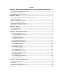
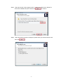
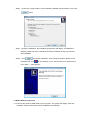
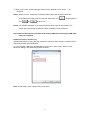
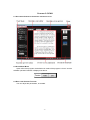
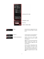
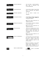
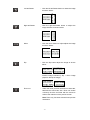
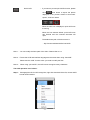
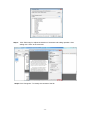
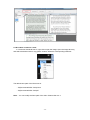
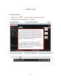
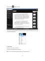
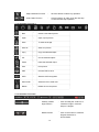
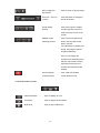
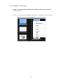
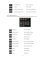
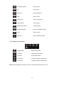
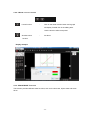
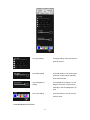
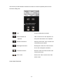
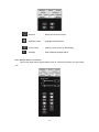
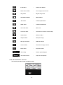
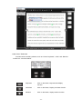
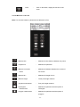
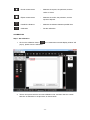
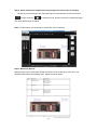
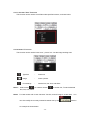
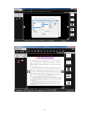
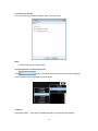
 KoPa Cam Software
User Manual
Ver 1.6
SHENZHEN OSTEC OPTO-ELECTRONIC TECHNOLOGY CO.,LTD.
http://www.ostec.com.cn
Content
CHAPTER 1: KOPA CAM SOFTWARE INSTALLATION AND DEVICE CONNECTION - - 1 1.1 SOFTWARE KOPA CAM INSTALLATION ---------------------------------------------------------------- - 1 1.2 WIRED DEVICE CONNECTION -------------------------------------------------------------------------- - 3 1.3 WIRELESS DEVICE CONNECTION ---------------------------------------------------------------------- - 4 CHAPTER 2: SCAN------------------------------------------------------------------------------------------ - 5 2.1 SOFTWARE OPERATION INTERFACE AND INSTRUCTION -------------------------------------------- - 5 2.2 SCAN WORK MODE -------------------------------------------------------------------------------------- - 5 2.3 REAL-TIME PREVIEW TOOLBAR ------------------------------------------------------------------------ - 5 2.4 REAL-TIME SCAN TOOLBAR----------------------------------------------------------------------------- - 8 2.5 PREVIEW SCREEN ADJUSTMENT----------------------------------------------------------------------- - 8 2.6 DOCUMENT THUMBNAIL FRAME ---------------------------------------------------------------------- - 14 CHAPTER 3: VIDEO ---------------------------------------------------------------------------------------- - 15 3.1 VIDEO WORK MODE ----------------------------------------------------------------------------------- - 15 3.2 SAVE VIDEO --------------------------------------------------------------------------------------------- - 16 CHAPTER 4: DOCUMENT EDITING ------------------------------------------------------------------- - 16 4.1 INTERFACE INSTRUCTION ----------------------------------------------------------------------------- - 17 4.1.1 Object Selection Toolbar ---------------------------------------------------------------------- - 17 4.1.2 Standard Toolbar 1 ----------------------------------------------------------------------------- - 18 4.1.3 Standard Toolbar 2 ----------------------------------------------------------------------------- - 18 4.1.4 View change column --------------------------------------------------------------------------- - 19 4.1.5 Thumbnail Active Area ------------------------------------------------------------------------ - 20 4.2 DOCUMENT EDITING FUNCTION ---------------------------------------------------------------------- - 21 4.2.1 “Drawing” Function ----------------------------------------------------------------------------- - 21 4.2.2 “Shape” Function ------------------------------------------------------------------------------- - 22 4.2.3 “Wipe” Function --------------------------------------------------------------------------------- - 25 4.2.4 “Settings” Function ----------------------------------------------------------------------------- - 26 4.2.5 “Screenshot”Function -------------------------------------------------------------------------- - 27 4.2.6 “Slide” Function --------------------------------------------------------------------------------- - 28 4.2.7 “Special Effect” Function ---------------------------------------------------------------------- - 29 4.2.8 “Record Screen” Function -------------------------------------------------------------------- - 30 4.2.9 “Tool” Function ---------------------------------------------------------------------------------- - 31 4.2.10“Measure” Function ---------------------------------------------------------------------------- - 32 4.2.11“Content Tree” Function ---------------------------------------------------------------------- - 36 4.2.12“Insert” Function -------------------------------------------------------------------------------- - 36 CHAPTER 5: ADVANCED SETTINGS ---------------------------------------------------------------- - 38 5.1 ADVANCED SETTINGS ---------------------------------------------------------------------------------- - 38 5.2 SETTING ------------------------------------------------------------------------------------------------- - 38 5.3 CONNECTED DEVICES ---------------------------------------------------------------------------------- - 39 5.4 INTERFACE LANGUAGE SELECTION ------------------------------------------------------------------ - 39 5.5 ABOUT --------------------------------------------------------------------------------------------------- - 39 -
CHAPTER 1: KOPA CAM
SOFTWARE INSTALLATION AND DEVICE CONNECTION
1.1 SOFTWARE INSTALLATION
Step1: Start your computer and insert the installation disc into the DVD driver.
Step2: Double-click the file “KoPa Cam Install ”under the disc content. When the following
window is displayed, please choose the installation language and press
”button.
Step3: When the window “Welcome to use KoPa Cam installation guide” is displayed,
please click “
”button.
‐ 1 ‐ Step4: When the window “Select target location” is displayed, please click “Browse” to
choose the installation file path. Please click
to continue.
Step5: When the following window is displayed, please select your desired shortcut and
then click
.
‐ 2 ‐ Step6: Confirm the “Target location” of the software installation and information. Then click
button.
Step7: During the installation, the installation progress bar will display. If installation is
delayed, please check your firewalls and antivirus software as they may interfere
with installation
Step8: Click
to finish the installation. After closing the window, please check
the KoPa Cam icon
on your desktop. If you cannot find the icon, please find it
from “Start” → “All programs”.
1.2 WIRED D EVICE C ONNECTION
1.2.1Connect the camera’s USB cable to your computer. The system will display “Find new
hardware” window and finish the driver installation automatically.
‐ 3 ‐ 1.2.2Run “KoPa Cam” software through shortcut on the desktop or from “Start” → “All
programs”.
Note 1: Before you use “KoPa Cam” software,please confirm that the device has been
connected to the USB port of the computer. Otherwise, only
and
and
can be operated
will fail to run.
Note 2: For multiple USB ports, if you insert the device into the port for the first time, the
system will automatically complete the driver installation for the USB port.
Note3: We recommend you close KoPa Cam software PRIOR to removing the USB cable
from your computer.
1.3 WIRELESS DEVICE CONNECTION
Detailed instructions for using the WiFi connection and KoPa Vision App are contained in the
respective Android and iOS Manuals.
On your computer, select the “Wireless Device Connection” option of the “Device” in the
advanced settings, and restart the software as below:
Note: In WiFi mode, some functions may not be used.
‐ 4 ‐ CHAPTER 2: SCAN
2.1 SOFTWARE OPERATION INTERFACE AND INSTRUCTION
2.2 SCAN W ORK MODE
Open KoPa Cam program, the default work mode of the program is “Scan” and the
software operation interface is displayed as above.
2.3 REAL-TIME PREVIEW TOOLBAR
You can adjust the parameters, as needed.
‐ 5 ‐ Focus
:
Check the box to trigger Auto Focus
the box or move the slider for manual
focus.
Exposure
:
Check the box for auto exposure or
use the slider for manual exposure.
Automatic White Balance
:
Check the box for auto white
balanceor use the slider for manual
white balance.
Note:The colors may seem abnormal
taking a photo rich in colors. You
need to manually calibrate the auto
white balance.
Place a sheet of white paper under
the microscope. Uncheck the auto
white balance box, wait for the
camera to adjust to neutral grey or
white and then recheck the box. Once
adjusted, uncheck the box a final
time.
‐ 6 ‐ Lightness Adjustment
:
Use the slider to adjust lightness.
Best used in conjunction with
Contrast adjustment.
Contrast Adjustment
:
Use the slider to adjust contrast. Best
used in conjunction with lightness
adjustment.
Saturation Adjustment
:
Use
the
slider
to
adjust
color
saturation
Overexposure Control
:
Use the slider to adjust the brightness
of the Preview when working in
strong light conditions.
Note: Some KoPa cameras do not
support this function.
Backlight Compensation
:
Use the slider to adjust the backlight
in the Preview mode.
Note: Some KoPa cameras do not
support this function.
LED Illumination
:
There are six lighting levels. Check
the box for Level 1and then use the
slider to adjust. LED lights will
automatically turn off if the box is
unchecked.
Note: Some KoPa models do not
support his function.
Power Line Adjustment
:
Use this function to ensure the device
and current voltage are the same
frequency in order to reduce the
“ripple” interference effect on the
preview screen.
Note: The frequency of the power
supply currently supports 50/60Hz,
Please select according to the
respective national power frequency.
Return to default settings
:
Click
to reset to the default
factory settings.
‐ 7 ‐ 2.4 REAL-TIME SCAN TOOLBAR
Real-time scan toolbar contains three parts: preview resolution,
photograph save resolution, photograph save format.
Preview Resolution
: Select as desired.
Note:The higher the resolution, the lower
the frame rate.
Save Resolution
: This option is used to select the saved the
photo resolution. The ratios of preview
resolution and preservation resolution are
consistent. When the preview resolution
ratio is 4:3, the preservation resolution
only supports the resolution selection of
4:3, i.e. the default maximum of
preservation resolution is 2592×1944.
When the preview resolution is 16:9, the
preservation resolution only supports the
resolution selection of 16:9, i.e. the default
preservation resolution is 1280×720.
Save Format
: Select from 4 image formats: .pdf,
.bmp, .jpg (default) and .png
2.5 PREVIEW SCREEN ADJUSTMENT
‐ 8 ‐ Left 90°Rotate
: Click the left 90°Rotate button to rotate the image
as shown below:
Right 90°Rotate
: Click the right 90°Rotate button to adjust the
image direction as shown below:
Mirror
: Click the mirror button to adjust adjust the image
as shown below:
Flip
: Click the flip button adjust the image as shown
below:
Preview image contrast by flip + mirror image
(equal to 180°flip of image).
Zoom out
: Under the lower preview resolutions of 640×480,
800×600 and 1024×768, click “Zoom out” button
or directly click the scroll bar with the mouse to
achieve the reduction of the preview screen.
Note: Zoom only functions at these lower preview
resolutions.
‐ 9 ‐ Zoom in
: Under preview resolution of 640×480, 800×600
and 1024×768, click “Zoom in” button or directly
click the scroll bar with the mouse to achieve the
magnification of the preview screen.
Note: Zoom only functions at these lower preview
resolutions.
Actual Size (1:1)
: Click on the button to enlarge the image to actual
size.
Adapt to width
: Click on the button to adjust the image size to
your application window.
Adapt to Screen
Full Screen
: Click on the button to shrink the image to your
screen. If the image is smaller, it will display
actual size.
: Click on the button for full screen display. Click
ESC to exit full screen display.
Camera
: Click the scan button to scan the image displayed
in the preview window.
Time Lapse
: Click the button for time lapse photography. Then
select the number of shots and intervals. Then
Start
‐ 10 ‐ ,as shown below:
Quick OCR
: If you want to process quick OCR function, please
Click
scan button to export the picture
displayed in the preview window to document.
Open it, as shown below:
When the wait icon is displayed, quick OCR scan
is running.
When the icon restores default, quick OCR scan
has finished and the scanned document will
open.
The default save path of the document is:
…\My Documents\Ostec\KoPa Cam\OCR
Note 1: You can modify the Save path of the video. Please refer to 5.2.
Note 2: Ensure the OCR and interface language are the same when using “fast OCR”.
Please use the “OCR” function when you need to modify the files.
Note 3: When using “quick OCR”, the OCR cannot recognize rotary characters.
The OCR operation is as follows:
Step 1: Photograph the file for OCR recognition, right click thumbnail of the file, choose“OCR”
to enter OCR interface.
‐ 11 ‐ Step 2: Choose the language for OCR interface or click More languages for selecting more
languages. Check the required language, check after clicking "ok"
Tips1: “Quick OCR” is only available when the language of the file for OCR corresponds with
the interface language. If you fails to find the corresponding language on the software
interface, you need to choose “OCR” for recognition.
Tips 2: “OCR” supports 168 languages from different countries.
Tips 3: The current software language is OCR’s recognition language. When the recognition
language corresponds with the current document language, the character
recognition function of OCR can perform at its best.
‐ 12 ‐ Step 3: Click “Edit Image” to adjust the direction of character and editing operation. After
editing click "close" to save and exit.
Step4: Click “Recognize ” To identify the contents of the file.
‐ 13 ‐ 2.6 DOCUMENT THUMBNAIL FRAME
In "document thumbnail frame", right click to open the image, Open the image directory,
and select the desired action: copy,paste, rename, delete the corresponding treatment.
The default save path of the Document is:
…\MyDocuments\KoPa Cam\picture
…\MyDocuments\KoPa Cam\pdf
Note: You can modify the Save path of the video. Please refer to 5.2
‐ 14 ‐ CHAPTER 3: VIDEO
3.1 VIDEO WORK MODE
When you click
, enter the video page. The following diagram:
Note: Please refer to instructions 2.3, 2.4, 2.5above.
Click the button
to record a video of the image displayed in the preview window.
‐ 15 ‐ Click the button
to stop the video.
You can open, copy, paste, delete, and rename the film, and open the catalog of the film in the
“document thumbnail box”.
3.2 S AVE VIDEO
The default save path of the video is:
…\My Documents\Ostec\KoPa Cam\video
Note: You can modify the Save path of the video. Please refer to 5.2
‐ 16 ‐ CHAPTER 4: DOCUMENT EDITING
4.1 INTERFACE INSTRUCTION
When you click
, the following interface will appear:
4.1.1 OBJECT SELECTION TOOLBAR
‐ 17 ‐ Object Selection Function
:
Click this button to select any operation.
Undo, Redo Function
:
Click this button to make undo the last step
or redo the next step” operation.
4.1.2 STANDARD TOOLBAR 1
New
:
Create a new blank picture.
Open
:
Open, import picture.
Save
:
To save the image.
Save as
:
Save as a picture.
Copy
:
Copy the selected object.
Cut
:
Cut the selected object.
Paste
:
Paste the selected object
Print
:
Print picture.
PDF
:
Convert PDF to save.
OCR
:
Start the OCR recognition.
Send email
:
Select the file to send mail.
Delete
:
Delete the current picture.
4.1.3 STANDARD TOOLBAR2
Arbitrary rotation
angle function
: Click and drag the scroll bar, to
rotate the image in minimum
steps of 1 degree.
Rotate function
: Click on this button to rotate 90
degrees clockwise or
anticlockwise.
‐ 18 ‐ Mirror Image and
: Click to mirror or flip the image.
Flip function
Zoom out、Zoom in
function
: Click this button to enlarge or
shrink the picture.
Image display
function
: Click left to right for: Display
actual image size, format to
width, format to screen or full
screen.
Multiple screen
switching function
: Click on the one-split-screen
button, the two-split-screen
button, and the
four-split-screen to display one
image, two images, and four
images respectively.
Click on one image, the
number of the selected picture
will turn red. Double click the
thumbnail to insert the red
number into inserted into the
window.
Synchronization
: Click. After two minutes,
screens function
screen splits into four
4.1.4 VIEW CHANGE COLUMN
Detail information
:
Click to display as a list.
Thumbnail
:
Click to display as thumbnails.
Slide show
:
Click to play a slide show..
‐ 19 ‐ 4.1.5 THUMBNAIL ACTIVE AREA
① When you select List Display, double-click an image to load it into the “document
editing work area”.
②
When you select picture List Display, right-click on an image for the following menu:
‐ 20 ‐ 4.2 DOCUMENT EDITING FUNCTION
4.2.1 “DRAWING” FUNCTION
Click on a selected button for different drawing functions:
Pencil
:
Pencil drawing.
Pen
:
Pen drawing.
Fine brush
:
Fine brush drawing.
Chalk
:
Chalk drawing .
Thick Brush
:
Thick Brush drawing .
Texture pen
:
Texture pen drawing.
Fill
:
Paint fill.
Layer up
:
Shifts the selected objects up a level.
Layer down
:
Shifts the selected objects down a level.
‐ 21 ‐ 4.2.2 “SHAPE ” FUNCTION
Click on the corresponding button to draw various lines and graphics in the document
editing work area.
4.2.2.1 D RAW
A LINE
Click on the corresponding button to draw various lines in the document editing work area.
.
Straight line
:
Draw a straight line.
Line with single arrow
:
Draw a single arrow straight.
Line with double arrow
:
Draw the double arrow straight.
Curve
:
Draw a curve.
‐ 22 ‐ Curve with arrow
:
Draw a curved arrow.
Polyline
:
Draw a polyline.
Polyline with single arrow
:
Draw a single arrow Polyline.
Polyline with double arrow
:
Draw a double arrow Polyline.
4.2.2.2 DRAWING GRAPHICS
Click on the relevant button to draw various graphics in the document editing work area.
Rectangle
:
Draw a rectangle.
Round rectangle
:
Draw a rounded rectangle.
Parallelogram
:
Draw a parallelogram.
Rhombus
:
Draw a rhombus.
Octagonal
:
Draw a polygon.
Isosceles triangle
:
Draw an isosceles triangle.
Orthogonal triangle
:
Draw a right angled triangle.
Concentric circles
:
Draw concentric circles.
Ellipse
:
Draw an ellipse.
Cylinder
:
Draw a cylinder.
Cube
:
Draw a cube.
‐ 23 ‐ 4.2.2.3 S IMPLE
Truncated pyramid
:
Draw a prism.
Arc
:
Draw an arc.
Hollow arc
:
Draw a hollow arc.
Moon
:
Draw a moon.
Smiling face
:
Draw a smiling face.
Heart-shaped
:
Draw a heart.
Break angle;dog-ear
:
Painting angle.
Prohibited Symbol
:
Draw a ‘Prohibited’ symbol.
Cross
:
Draw a cross
Lightning
:
Draw a lightning symbol.
MEASUREMENT
Straight edge
: Ruler measurement.
Compass
: Compass measurement.
Protractor
: Angle measurement
30°triangle
: 30 degree triangle measurement.
45°triangle
: 45 degree triangle measurement.
Note:Please calibrate the camera for more accurate measurements. See 4.2.10.
‐ 24 ‐ 4.2.2.4 D RAW
FUNCTION FIGURE
Linear function
:
Click on the linear function button and a graph
will display. Double click in the editing area.
Use the function editor as required.
Absolute value
:
As above.
function
Display example:
4.2.3 “ERASE/WIPE” FUNCTION
This function provides different erase functions, such as circular erase, object erase and erase
all etc.
‐ 25 ‐ Round erase
:
Draw a circular area to erase.
Random
:
Erases wherever you guide the eraser.
:
Draw a rectangle to erase.
Specific
:
Erase specific selected areas.
Erase all
:
Erases everything.
erase
Selection
erase
4.2.4“SETTINGS” FUNCTION
If you are going to draw custom lines and graphs, please click on the settings button, first This
includes setting the line type, the line width, the transparency, and colors of graphs in the
“drawing function” and in the “shape function”.
‐ 26 ‐ Line type setting
:
Line type setting: There are five line
types to choose.
Line width setting
:
Line width setting: You can drag the
scroll bar or input values manually
to set the line width.
Line transparency
:
setting
Line transparency setting: You can
drag the scroll bar or input values
manually to set the transparency of
lines.
Line color setting
:
Line color setting: You can set the
colors of lines.
4.2.5“SCREENSHOT”FUNCTION
‐ 27 ‐ This function provides different screenshot functions to insert the captured picture into the
document editing area.
Clip
:
Cut the rectangular area drawn.
Send screenshot to
:
Take a screen shot to the clipboard: Cut
clipboard
Random screenshot
the square area drawn to the clipboard.
:
Arbitrary screen shot: Take a screen shot
of the arbitrary area drawn.
Rectangle screenshot
:
Rectangular screen shot: Take a screen
shot of the rectangular area drawn.
Screenshot window
:
Window screen shot:Take a screen shot
of the window area.
Print screen
:
Screen shot: Take a screen shot of the
whole screen.
4.2.6 “SLIDE ” FUNCTION
.
‐ 28 ‐ Blackout
:
Blacks out the entire screen.
Highlight screen
:
Highlights selected areas.
Cover screen
:
Partially covers screen for later display.
Spotlight
:
Select different spotlight effects.
4.2.7 “SPECIAL EFFECT” FUNCTION
This function adds various special effects such as “monochrome effect” and “grey effect”
etc.
‐ 29 ‐ Invert effect
:
Inverts color effects.
Monochrome effect
:
Turns image monochrome..
Grey effect
:
Adjusts Grey tones.
Add shadows effect
:
Add shadows.
Jitter effect
:
Creates a jitter effect.
Relief effect
:
Creates a relief effect.
Add noise effect
:
Add noise.
Corrosion effect
:
The effect of corrosion on the image.
Soften effect
:
Diffusion effect.
Sharpen effect
:
Sharpens image.
Red-eye correction
:
Reduces red eye
Contour effect
:
The effect of image contour.
Bulge effect
:
Expansion effect.
Text Clarity
:
Cleans up text displays.
Text enhancement
:
Improves text displays.
4.2.8 “RECORD SCREEN” FUNCTION
This function provides screen recording function.
‐ 30 ‐ 4.2.9 “TOOL” FUNCTION
Provides various auxiliary software, such as “Screen keyboard”, “Clock” and “Random
number” etc. As shown below:
Keyboard
:
Click on the button, keyboard and display
function.
Calculator
:
Click on the button, Display calculator function.
Random
:
Click on the button, display random function.
‐ 31 ‐ Clock
:
Click on the button, display the function of the
clock.
4.2.10“MEASURE” FUNCTION
Note: For accurate measure, please set the calibration at first.
Measure line
:
Measure the line distance between two points.
Polyline line
:
Measure the perimeter.
Measure concentric
:
Measure the distance between the centers of
circles
two circles.
Measure arc
:
Measure the length of arcs.
Measure angle
:
Three point angle measure.
Angular measurement
:
Four point angle measure.
Rectangular
:
Measure the perimeter and the square of
measurement
Polygon measurement
rectangles.
:
Measure the perimeter and the square of
polygons.
‐ 32 ‐ Round measurement
:
Measure the square, the perimeter, and the
radius of circles.
Ellipse measurement
:
Measure the radius, the perimeter, and the
square of ellipses.
Parallel line distance
:
Measure the distance between parallel lines.
Calibration
:
Set the calibration.
CALIBRATION
Step 1: Set calibration
1. Click on the calibration button “
”, the “measurement results display window” will
pop up, please choose “calibration”.
2. Take a clear picture with the accurate calibration ruler, and then draw the custom
base line of calibration in the plot area, as shown below:
‐ 33 ‐ 3. The calibration parameter setting in the “measurement results display window” Set
step by step, from ①→②→③→④→⑤, as shown blow:
①Input the custom length of calibration
②Choose the unit consistent to the base line
③Choose the record of this line
④Click on “calibration setting”, the first grid will display “*”, and finish.
⑤Click on “out” and close the window.
‐ 34 ‐ Step 2: Actual measurement (take measuring straight lines and circles as example)
Double click on the image of the measured object in the thumbnail, choose the line tool
“
” and the circle tool “
” in measuring tools, and then choose the measuring target.
The result will be shown as below.
Note: For best results, set the image to “actual size” when measuring.
Step 3: Measuring Results
Measurements can be exported to WORD or EXCEL. Fill in the file name, and "save", the
generated files will be automatically open. Appear as shown below:
‐ 35 ‐ 4.2.11“CONTENT TREE” FUNCTION
This function can be used to check files under specified content, as shown below.
4.2.12“INSERT” FUNCTION
This function can be used to insert “text”, “picture” etc. into the image working area.
Typeface
:
Insert text.
Image
:
Insert a picture.
Font settings
:
Set the font, font, size, and effect.
Note 1: Select Insert
, you need to choose
font, font, size, effect.
to set the font, To set the desired
Note2: For best results with “insert character” function, ensure image is “actual size” . You
can also modify the currently inserted character font by the
An example is shown below:
‐ 36 ‐ function.
‐ 37 ‐ CHAPTER 5: ADVANCED SETTINGS
5.1 ADVANCED SETTINGS
Click
button for the following settings screen.
5.2 SETTING
Click
button in the advanced option. “Scan”, and the “Device” will be
displayed.
Photograph: You can choose the image storage path for PDF documents, OCR, Word and
Excel files and also video files.
‐ 38 ‐ 5.3 CONNECTED DEVICES
You can connect your device via USB or WiFi, as shown below:
Note:
1. Some models do not support WiFi.
5.4 THE INTERFACE LANGUAGE SELECTION
Click
button in the advanced option button and 6 kinds of language
version selection will be displayed. As shown below:
5.5 ABOUT
Click“About”Option,There will be detailed information of equipment and software.
‐ 39 ‐ ‐ 40 ‐