1
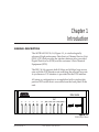
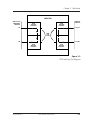
DSU 56/64
Data Service Unit
USER MANUAL
61200.062L1-1D
May 1997
901 Explorer Boulevard
P.O. Box 140000
Huntsville, AL 35814-4000
Phone: (205) 963-8000
© 1997 ADTRAN, Inc.
All rights reserved.
Printed in USA.
FCC regulations require that the following information be provided in this manual:
1. This equipment complies with Part 68 of the FCC rules. On the bottom of the
equipment housing is a label that shows the FCC registration number and Ringer
Equivalence Number (REN) for this equipment. If requested, provide this
information to the telephone company.
2. If this equipment causes harm to the telephone network, the telephone company may
temporarily discontinue service. If possible, advance notification is given, otherwise,
notification is given as soon as possible. The telephone company will advise the
customer of the right to file a complaint with the FCC.
3. The telephone company may make changes in its facilities, equipment, operations, or
procedures that could affect the proper operation of this equipment; advance
notification and the opportunity to maintain uninterrupted service is given.
4. If experiencing difficulty with this equipment, please contact ADTRAN for repair and
warranty information. The telephone company may require this equipment to be
disconnected from the network until the problem is corrected, or it is certain the
equipment is not malfunctioning.
5. This unit contains no user serviceable parts.
6. An FCC compliant telephone cord with a modular plug is provided with this
equipment. This equipment is designed to be connected to the telephone network or
premises wiring using an FCC compatible modular jack, which is Part 68 compliant.
7. The following information may be required when applying to the local telephone
company for leased line facilities.
Service
Type
56 kbps Digital Interface
Digital Facility
Interface Code
Service Order
Code
Network
Jacks
04DU5-56
6.0F
RJ-48S
FEDERAL COMMUNICATIONS COMMISSION
RADIO FREQUENCY INTERFERENCE STATEMENT
This equipment has been tested and found to comply with the limits for a Class A digital
device, Pursuant to Part 15 of the FCC Rules. These limits are designed to provide
reasonable protection against harmful interference when the equipment is operated in a
commercial environment. This equipment generates, uses, and can radiate radio frequency
energy and, if not installed and used in accordance with the instruction manual, may cause
harmful interference to radio frequencies. Operation of this equipment in a residential area
is likely to cause harmful interference in which case the user will be required to correct the
interference at his own expense.
Shielded cables must be used with this unit to ensure compliance with Class A FCC limits.
Change or modifications to this unit not expressly approved by the
party responsible for compliance could void the user's authority to
operate the equipment.
CANADIAN EMISSIONS REQUIREMENTS
This digital apparatus does not exceed the Class A limits for radio noise emissions
from digital apparatus as set out in the interference-causing equipment standard
entitled “Digital Apparatus," ICES-003 of the Department of Communications.
Cet appareil nuerique respecte les limites de bruits radioelectriques applicables aux
appareils numeriques de Class A prescrites dans la norme sur le materiel brouilleur:
“Appareils Numeriques,” NMB-003 edictee par le ministre des Communications.
Table of Contents
Chapter 1. Introduction
General Description ................................................................................................................ 1
Physical Description ............................................................................................................... 2
Front Panel ....................................................................................................................... 3
LED Identification .................................................................................................... 3
DTE Status (Green) ........................................................................................... 3
Network Status (Red) ....................................................................................... 3
Test Status/Error (Yellow/Red) ...................................................................... 3
Test Switches ............................................................................................................. 4
Rear Panel ......................................................................................................................... 5
Chapter 2. Installation
Unpack, Inspect, Power Up ................................................................................................... 7
Receiving Inspection ....................................................................................................... 7
ADTRAN Shipments Include ........................................................................................ 7
Customer Provides .......................................................................................................... 7
Power Up .......................................................................................................................... 8
Warranty and Customer Service .......................................................................................... 9
Configuration ........................................................................................................................ 10
Clear To Send (CS) - SW 1 ............................................................................................ 10
Clear To Send Delay (CS Delay) - SW 2 ..................................................................... 10
Antistream - SW 3 .......................................................................................................... 10
Carrier Detect (CD) - SW 4 ........................................................................................... 11
Data Set Ready (SR) - SW 5 .......................................................................................... 11
Remote Digital Loopback (RDL) - SW 6 ..................................................................... 11
Loop Rate - SW 7 ........................................................................................................... 12
Scrambler - SW 8 ............................................................................................................ 12
Network Connections .......................................................................................................... 13
DTE Connector .............................................................................................................. 13
Chapter 3. Test Modes
Self Test ................................................................................................................................... 15
Near End Tests ...................................................................................................................... 16
DTE Only Test ................................................................................................................ 16
DTE with Test Pattern (TP) .......................................................................................... 18
DTE and Loop Test (LL) ............................................................................................... 20
61200.062L1-1
DSU 56/64 User Manual
i
Table of Contents
Loop Only Test .............................................................................................................. 22
Far End Tests ......................................................................................................................... 23
Remote Digital Loopback (RDL) ................................................................................. 23
RDL with Test Pattern (TP) .......................................................................................... 23
Test Pattern (PTRN) ...................................................................................................... 24
Remote Tests .......................................................................................................................... 25
Chapter 4. Specifications Summary
Specifications and Features ................................................................................................. 27
Loop Interface .................................................................................................. 27
Line Requirements .......................................................................................... 27
Loop Rates ........................................................................................................ 27
Receiver Sensitivity ......................................................................................... 27
DTE Interfaces ................................................................................................. 27
DTE Operating Modes ................................................................................... 27
DTE Data Rates ................................................................................................ 27
Diagnostics ....................................................................................................... 28
Power ................................................................................................................ 28
Environment .................................................................................................... 28
Index ....................................................................................................................................... 29
List of Tables
Table 2-A Network Connections ..................................................................................... 13
Table 2-B DTE Pin Assignments ..................................................................................... 14
List of Figures
Figure 1-1 DSU 56/64 Front Panel .................................................................................... 1
Figure 1-2 DSU 56/64 Rear Panel ...................................................................................... 5
Figure 3-1 DTE Only Test Diagram ................................................................................. 17
Figure 3-2 DTE with TP Test Diagram ............................................................................ 19
Figure 3-3 DTE and Loop Test Diagram ......................................................................... 21
Figure 3-4 Loop Only Test Diagram ................................................................................ 22
ii
DSU 56/64 User Manual
61200.062L1-1
Chapter 1. Introduction
Chapter 1
Introduction
GENERAL DESCRIPTION
The ADTRAN DSU 56/64, Figure 1-1, is a technologically
advanced, high performance Data Service/Channel Service Unit
(DSU/CSU) that provides the interface between telco provided
Digital Data Service (DDS) and the customer’s Data Terminal
Equipment (DTE).
The DSU 56/64 supports both 56 kbps and 64 kbps loop service
rates with the DTE interface rate matching the selected loop rate.
A synchronous V.35 interface is provided for the DTE interface.
All setup or configuration is accomplished with a single eightposition DIP switch that is accessible from the back panel of the
unit.
DSU 56/64
TEST
RS
CS
TD
RD
CD
ALM
DTE
LOOP
RDL
PTRN ERROR
SELECT
TEST
Figure 1-1
DSU 56/64 Unit
61200.062L1-1
DSU 56/64 User Manual
1
Chapter 1. Introduction
PHYSICAL DESCRIPTION
The DSU 56/64 is a single stand-alone unit designed to be used
either on a desktop or mounted on a wall. The physical measurements of the DSU 56/64 are as follows:
Length
Width
Height
Weight
2
=
=
=
=
8.32 inches
6.50 inches
1.56 inches
1.50 pounds
DSU 56/64 User Manual
61200.062L1-1
Chapter 1. Introduction
Front Panel
As shown in Figure 1-1, the front panel of the DSU 56/64 contains eleven light emitting diode (LED) indicators that display
DTE interface, network, and test status. These indicators are
defined in the section LED Identification.
LED Identification
DTE Status (Green)
INDICATOR
RS
CS
TD
RD
CD
DEFINITION
Request To Send
Clear To Send
Transmit Data
Receive Data
Carrier Detect
SOURCE
DTE
DSU
DTE
DSU
DSU
The active state for the status indicators (RS, CS, and CD) is On while
the on state for the data indicators (TD and RD) represents a Space
condition.
Network Status (Red)
ALM
On indicates a problem on the local loop or within
the DDS network.
Off indicates normal loop and network conditions.
Test Status/Error (Yellow/Red))
61200.062L1-1
DTE
On solid indicates DTE interface test in progress.
Flashing indicates Loop Interface test (CSU
Loopback) has been initiated by telco.
Loop
On solid indicates loop interface test has been
initiated from local DSU.
Flashing indicates loop interface test (CSU or DSU
Loopback) has been initiated by telco.
DSU 56/64 User Manual
3
Chapter 1. Introduction
RDL
On solid indicates remote digital loopback test has
been initiated from the local DSU.
Flashing indicates remote digital loopback test has
been initiated from the remote DSU.
PTRN
On solid indicates that integral pattern generator is
being utilized for testing.
Error
On indicates that errors are being detected during a
test or that a test can not be properly initiated.
Tests defined by the above indicators are explained in greater
detail in the chapter Test Modes.
Test Switches
The front panel also contains two push-button switches for
selecting and controlling the various test modes for the DSU 56/
64. The descriptions of these switches are as follows:
4
Select
Each time this switch is activated a valid test mode
is indicated by one or more LEDs being turned on
solid.
Test
Once the desired test mode is displayed on the test
status indicators, the test is initiated by activating
this switch. This switch is also activated to terminate any test in progress.
DSU 56/64 User Manual
61200.062L1-1
Chapter 1. Introduction
Rear Panel
The rear panel of the DSU 56/64 is shown in Figure 1-2. The
thirty-four pin connector labeled PRIMARY V.35 provides the
synchronous DTE interface. The eight-pin modular jack (RJ-48S)
labeled TELCO connects the DSU 56/64 to the DDS network.
The pin assignments for these connectors are described in the
sections Network Connections and DTE Connections.
TELCO
PRIMARY V.35
OPTIONS
(LISTED ON BOTTOM)
1
2
3
4
5
6
7
8
115 VAC
60HZ .06A
Figure 1-2
DSU 56/64 Rear Panel
All setup or configuration parameters for the DSU 56/64 are
selected with an eight-position DIP switch. This switch, labeled
OPTIONS, is accessible from the rear panel. The label also
references the options chart located on the bottom of the unit.
The individual options are explained in detail in the section
Configuration.
The power cord on the rear panel of the DSU 56/64 is mechanically secured to the back panel and provides the connections to
the integral AC/DC power supply.
61200.062L1-1
DSU 56/64 User Manual
5
Chapter 1. Introduction
6
DSU 56/64 User Manual
61200.062L1-1
Chapter 2. Installation
Chapter 2
Installation
UNPACK, INSPECT, POWER UP
Receiving Inspection
Carefully inspect the DSU 56/64 for any shipping damages. If
damage is suspected, file a claim immediately with the carrier
and then contact ADTRAN Customer Service. If possible, keep
the original shipping container for use in returning the unit for
repair or for verification of damage during shipment.
ADTRAN Shipments Include
The following items are included in ADTRAN shipments of the
DSU III TDM:
• The DSU 56/64 unit
• Network interface cable
An 8-position modular to 8-position modular
• The DSU 56/64 User Manual
Customer Provides
The customer must provide a V.35 cable.
61200.062L1-1
DSU 56/64 User Manual
7
Chapter 2. Installation
Power Up
The DSU 56/64 is equipped with a captive six-foot power cord
that is terminated with a three-prong plug for connecting to a
grounded power receptacle.
Ensure that a grounded, 115 VAC, 60 Hz receptacle is used for powering the DSU 56/64.
When plugged into a source of AC power, the DSU 56/64
performs a self test to verify all LED indicators plus various
circuit blocks within the unit. See the section Self Test.
8
DSU 56/64 User Manual
61200.062L1-1
Chapter 2. Installation
WARRANTY AND CUSTOMER SERVICE
ADTRAN will replace or repair this product within five years
from the date of shipment if it does not meet its published
specifications or fails while in service. For detailed warranty,
repair and return information refer to the ADTRAN Equipment
Warranty and Repair and Return Policy Procedure.
Return Material Authorization (RMA) is required prior to
returning equipment to ADTRAN.
For service, RMA requests or more information, contact one of
the numbers listed on the inside back cover of this manual.
61200.062L1-1
DSU 56/64 User Manual
9
Chapter 2. Installation
Configuration
The DSU 56/64 has eight options for controlling the operation of
both the network and DTE interfaces. These options are selected
by setting individual switches on the eight-position DIP switch
that is accessible from the rear panel. A chart showing the
options and switch settings is attached to the bottom of the unit.
Clear To Send (CS) - SW 1
Down – Normal
In the Down position CS follows the RS lead with the selected
amount of delay. The only exceptions to this occur when network or test conditions prevent data from being transferred over
the DTE interface. During these conditions CS is turned off.
Up – On
CS is forced on all the time.
Clear To Send Delay (CS Delay) - SW 2
Switch Position
Down - Short
Up - Long
RS To CS Delay
250 µs ± 125 µs
10 ms ± 125 µs
Antistream - SW 3
The Antistream option is used to select the antistream time out.
The antistream time out is the maximum time the DSU 56/64 is
allowed to transmit data from the DTE into the network. This
feature prevents one DTE device on a multi-drop network from
continuously tying up the transmit circuit from a remote DSU
back to the master DSU.
The antistream timer is reset to zero when RS transitions to the
active state and is updated every second while RS is active.
When the antistream time out expires, the DSU 56/64 stops
transmitting DTE data into the network. It does, however,
continue to accept data. CS is maintained in the active state until
the DTE deactivates the RS input.
10
DSU 56/64 User Manual
61200.062L1-1
Chapter 2. Installation
Down – Off
The Antistream timer is disabled.
Up – On
The Antistream timer is enabled and set for 45 +/- 0.5 seconds.
Carrier Detect (CD) - SW 4
Down – Normal
CD is on any time customer data is being received and off when
the receive circuit is idle, not carrying customer data.
Up – On
CD is forced on all the time.
Data Set Ready (SR) - SW 5
Down – On
SR is forced on all the time.
Up – Normal
SR is only turned off when the network is out of service or a test
is in progress.
Remote Digital Loopback (RDL) - SW 6
Down – Enable
The DSU 56/64 accepts the industry standard V.54 RDL command from the far end of the circuit.
Up – Disable
The DSU 56/64 does not respond to the V.54 loopback command
from the far end of the circuit.
61200.062L1-1
DSU 56/64 User Manual
11
Chapter 2. Installation
Loop Rate - SW 7
Down – 56 kbps
The network interface of the DSU 56/64 is configured for
operation at 56 kbps.
Up – 64 kbps
The network interface is configured for 64 kbps operation.
Scrambler - SW 8
For 64 kbps clear channel operation, there is a possibility that the
DTE data sequences might mimic network loop maintenance
functions and erroneously cause other network elements to
activate loopbacks. To prevent this, the Scrambler switch should
be set to the Down (ON) position.
The Scrambler On option must be selected in both the local and
remote 56/64 DSUs for the situation described above.
This option is only valid when the 64 kbps rate is selected.
Down - On
The scrambler is enabled.
Up - Off
The scrambler is disabled.
12
DSU 56/64 User Manual
61200.062L1-1
Chapter 2. Installation
NETWORK CONNECTIONS
This interface consists of four leads that are paired to provide
separate transmit and receive circuits. The four leads are provided on the eight-position modular jack DSU RJ-48S labeled
TELCO on the rear panel of the DSU 56/64. The pin assignments for this connector are shown in Table 2-A.
Table 2-A
Network Connections
Pin
Number
1
2
3-6
7
8
Function
Signal Direction
Transmit Data (R)
Transmit Data (T)
Not Used
Receive Data (T-1)
Receive Data (R-1)
From Customer to Network Interface
From Customer to Network Interface
From Network Interface to Customer
From Network Interface to Customer
DTE Connector
The Data Terminal Equipment is attached to the connector
labeled PRIMARY V.35 at the rear of the DSU 56/64. Table 2-B
shows the pin assignments for all pins used on this connector.
61200.062L1-1
DSU 56/64 User Manual
13
Chapter 2. Installation
Table 2-B
DTE Pin Assignments
Pin
A
B
C
D
E
F
R
T
V
X
P
S
Y
AA
U
W
CCITT
Description
101
102
105
106
107
109
104
104
115
115
103
103
114
114
113
113
Protective Ground (PG)
Signal Ground (SG)
Request to Send (RS)
Clear to Send (CS)
Data Set Ready (SR)
Receive Line Signal Detector (CD)
Received Data (RD-A)
Received Data (RD-B)
Receiver Signal Element Timing (SCR-A)
Receiver Signal Element Timing (SCR-B)
Transmitted Data (SD-A)
Transmitted Data (SD-B)
Transmitter Signal Element Timing (SCT-A)
Transmitter Signal Element Timing (SCT-B)
External TX Signal Element Timing (SCX-A)
External TX Signal Element Timing (SCX-B)
A shielded V.35 cable is required to prevent possible radio frequency
interference emissions.
14
DSU 56/64 User Manual
61200.062L1-1
Chapter 3. Test Modes
Chapter 3
Test Modes
In addition to a self test mode, the DSU 56/64 has other extensive test modes which are designed to help isolate problems to
specific components of the communications circuit. These
various test modes for the DSU 56/64 are initiated and terminated from the front panel using the Select and Test.
SELF TEST
When the DSU 56/64 is powered on, all LEDs on the front panel
turn On simultaneously for approximately two seconds. After
the two seconds, all the LEDs turn Off briefly. The LEDs then
cycle On in pairs with a fan-out pattern away from the ALM
indicator. Next, the LEDs cycle Off in pairs with a fan-in pattern
back towards the ALM indicator. These patterns are repeated
four times for visual verification that all LEDs are functioning
properly.
At the completion of the LED test patterns the PTRN LED is On
indicating that the DTE with TP test is being performed. This
test is successful when the Error indicator does not turn On. If
the DTE with TP test fails, the RS, ALM, DTE, PTRN, and Error
indicators all Flash.
If a EPROM CHECKSUM failure is detected during self test, CS,
ALM, PTRN, and Error indicators all Flash at the end of the self
test.
61200.062L1-1
DSU 56/64 User Manual
15
Chapter 3. Test Modes
NEAR END TESTS
The local DSU 56/64 is capable of performing the following near
end tests:
• DTE Only
• DTE with Test Pattern
• DTE and LOOP (LL)
• Loop Only (RT)
DTE Only Test
The DTE Only test provides a method for testing both the DTE
interface of the local DSU 56/64 plus its loop transmitter and
receiver. For this test, the loop transmit data is connected to the
loop receive data at a point close to the physical network interface. A block diagram illustrating the loopback point and the
signal paths for this test is shown in Figure 3-1.
To initiate the DTE Only test, perform the following steps:
1. Press Select once to turn On the DTE test indicator.
2. Press Test while the test indicator is On.
To terminate this test, press Test.
Test data from the terminal or test equipment is routed through
the DTE section of the DSU 56/64 and then to the output of the
loop transmitter section where the signal is encoded for transmission. The output of the loop transmitter is coupled back to
the loop receiver input. The received test signal is then decoded
and returned to the terminal or test equipment where it is
checked for any bit errors.
16
DSU 56/64 User Manual
61200.062L1-1
Chapter 3. Test Modes
DTE or Test
Equipment
Interface
56/64 DSU
DTE
Transmit
Interface
Loop
Transmit
Interface
Network
Interface
Loop TX
TD
DTE
Only
RD
Loop RX
DTE
Receive
Interface
Loop
Receive
Interface
Figure 3-1
DTE Only Test Diagram
61200.062L1-1
DSU 56/64 User Manual
17
Chapter 3. Test Modes
DTE with Test Pattern (TP)
The DTE with TP test is similar to the DTE Only test previously
described. It is initiated at the local DSU 56/64 and is used to
independently test the operation of the DSU 56/64.
To initiate the DTE with TP test, perform the following steps:
1. Press Select twice to turn On both the DTE and PTRN test
indicators.
2. Press Test while these test indicators are On.
To terminate this test, press Test.
Instead of using data from the terminal or test equipment, this
test utilizes an internal test pattern generator and detector in the
DSU 56/64. The loopback point and the data paths for this test
are illustrated in Figure 3-2.
The internal test pattern generator and detector of the DSU 56/
64 operate with a 2047 data pattern. When this test is initiated,
the test pattern detector examines the receive data stream until
synchronization to the 2047 pattern is achieved. Once synchronized, the detector continues to check the receive data and
reports any detected bit errors by turning On the Error LED.
Once a test is initialized with the internal test pattern generator
and detector, errors can be injected into the transmit data stream
by pressing Select and observed by watching the Error LED turn
On for a brief period of time.
As previously mentioned, the DTE with TP is automatically
performed during the self test sequence for the DSU 56/64.
18
DSU 56/64 User Manual
61200.062L1-1
Chapter 3. Test Modes
Test
Pattern
Generator
DTE or Test
Equipment
Interface
DTE
Transmit
Interface
56/64 DSU
Loop
Transmit
Interface
Network
Interface
Loop TX
TD
DTE
with
Test Pattern
RD
Loop RX
DTE
Receive
Interface
Loop
Receive
Interface
Test
Pattern
Detector
Figure 3-2
DTE with TP Test Diagram
61200.062L1-1
DSU 56/64 User Manual
19
Chapter 3. Test Modes
DTE and Loop Test (LL)
This test is initiated at the local DSU 56/64 and allows independent testing of the separate sections of the DSU 56/64. Testing
includes testing of the local DTE interface with data from the
terminal or test equipment and testing of the loop interface
section of the local DSU 56/64 from the remote site over the
actual communications circuit. Testing from the remote end of
the circuit is performed with test data generated by the remote
DSU or terminal type test equipment.
The DTE and Loop test splits the DSU 56/64 into separate DTE
and Loop interface sections and then loops the transmit data of
each interface back to its respective receive data. Figure 3-3
illustrates the loopback points and the signal paths for this test.
The DTE and Loop LEDs Flash during initialization of the test
and turn On solid once the test is in progress.
To initiate the DTE and Loop test, perform the following steps:
1. Press Select three times to turn On both the DTE and Loop
test indicators.
2. Press Test while these test indicators are On.
To terminate this test, press Test.
20
DSU 56/64 User Manual
61200.062L1-1
Chapter 3. Test Modes
56/64 DSU
DTE or Test
Equipment
Interface
DTE
Transmit
Interface
Loop
Transmit
Interface
Network
Interface
Loop TX
TD
DTE
and
Loop
RD
Loop RX
DTE
Receive
Interface
Loop
Receive
Interface
Figure 3-3
DTE and Loop Test Diagram
61200.062L1-1
DSU 56/64 User Manual
21
Chapter 3. Test Modes
Loop Only Test
The Loop Only test is used to test the loop interface and a major
portion of the DTE interface of the local DSU 56/64 from the
remote site over the actual digital data circuit.
For the Loop Only test, the network receive data is looped to the
network transmit data inside the DTE interface section of the
DSU 56/64. The physical DTE interface is ignored for this test.
The Loop LED Flashes during initialization of the test and turns
On solid once the test is in progress. Figure 3-4 is a block diagram illustrating the loopback point and the signal paths for this
test.
To initiate the Loop Only test, perform the following steps:
1. Press Select four times to turn On the Loop test indicator.
2. Press Test while this test indicator is On.
To terminate this test, press Test.
DTE or Test
Equipment
Interface
56/64 DSU
DTE
Transmit
Interface
Loop
Transmit
Interface
Network
Interface
Loop TX
TD
Loop
Only
RD
Loop RX
DTE
Receive
Interface
Loop
Receive
Interface
Figure 3-4
Loop Only Test Diagram
22
DSU 56/64 User Manual
61200.062L1-1
Chapter 3. Test Modes
FAR END TESTS
Remote Digital Loopback (RDL)
When the RDL test is initiated at the local DSU 56/64, it commands the remote DSU into loopback with the industry standard
V.54 loopback pattern. The loopback point and the signal paths
for the remote DSU are the same as the Loop Only test for a local
DSU, shown in Figure 3-4. This loopback test is performed with
data from the terminal or test equipment. The RDL LED Flashes
during initialization of the test and turns On solid once the test is
in progress.
To initiate the RDL test, perform the following steps:
1. Press Select five times to turn On the RDL test indicator.
2. Press Test while this test indicator is On.
To terminate this test, press Test.
RDL with Test Pattern (TP)
When the RDL with TP test is initiated at the local DSU 56/64,
the local DSU commands the remote DSU into loopback with the
industry standard V.54 loopback pattern. The loopback point
and the signal paths for the remote DSU are the same as the
Loop Only test for a local DSU; see Figure 3-4. This loopback
test is performed with data from the internal test pattern generator and error detector. The RDL and PTRN LEDs Flash during
initialization of the test and turn On solid once the test is in
progress.
To initiate the RDL with TP test, perform the following steps:
1. Press Select six times to turn On both the RDL and PTRN
test indicators.
2. Press Test while these test indicators are On.
To terminate this test, press the Test switch.
61200.062L1-1
DSU 56/64 User Manual
23
Chapter 3. Test Modes
Test Pattern (PTRN)
When the PTRN test is initiated, the local DSU 56/64 uses the
integral test pattern generator to transmit a standard 2047 test
pattern to the DSU on the far end of the circuit. The local DSU
56/64 then examines the received data for the standard 2047
pattern. Once this pattern is detected and synchronization is
achieved, the Error indicator is turned Off. The Error indicator
turns On when errors in the receive data pattern are detected.
While this test is active, errors can be injected into the transmit
data stream by pressing the Test push-button. The PTRN LED
Flashes during initialization of the test and turns On solid once
the test is in progress.
To initiate the PTRN test, perform the following steps:
1. Press Select seven times to turn On the PTRN test indicator.
2. Press the Test switch while this test indicator is On.
To terminate this test, press Test.
24
DSU 56/64 User Manual
61200.062L1-1
Chapter 3. Test Modes
REMOTE TESTS
The DSU 56/64 responds to three remotely activated tests.
• Remote Digital Loopback (RDL)
• CSU Loopback (LL)
• DSU Loopback (RT)
The RDL test is initiated by a remote DSU and causes the local
DSU 56/64 to loopback. The loopback point is the same as the
Loop Only point. See Figure 3-4. This test is run to test the endto-end performance of the circuit.
Both the CSU Loopback and the DSU Loopback tests are activated from the telephone company diagnostic test equipment
and are used to isolate trouble on a circuit.
The CSU Loopback, commonly called the LL test, has the same
loopback points as the DTE and Loop test. It is used by the
telephone company to test the integrity of the local loop.
The DSU Loopback, commonly called the RT test, has the same
loopback point as the Loop Only test and is used by the telephone company to test the operation of both the local loop and
DTE interface sections.
61200.062L1-1
DSU 56/64 User Manual
25
Chapter 3. Test Modes
26
DSU 56/64 User Manual
61200.062L1-1
Chapter 4. Specifications Summary
Chapter 4
Specifications Summary
SPECIFICATIONS AND FEATURES
This section describes the standard specifications and features
incorporated in the DSU 56/64.
Loop Interface
4-wire, full duplex
Line Requirements
Local loop specifications per AT&T Pub 62310
Loop Rates
56 kbps or 64 kbps
Receiver Sensitivity
-45 dB
DTE Interfaces
V.35 synchronous
DTE Operating Modes
Full or half duplex
DTE Data Rates
56 kbps or 64 kbps synchronous
61200.062L1-1
DSU 56/64 User Manual
27
Chapter 4. Specifications Summary
Diagnostics
• Network test center activated:
- CSU loopback on sealing current reversal in local loop
- DSU loopback
• User activated:
- Self test
- Local loopback
- V.54 activated remote loopback with:
2047 test pattern
DTE data/data from external test set
Power
115 VAC
4 Watts (maximum)
Environment
• Temperature
- Operating
- Storage
0°C to 50°C (32°F to 122°F)
-20°C to 70°C (-4°F to 158°F)
• Relative Humidity up to 95%, non-condensing
28
DSU 56/64 User Manual
61200.062L1-1
Index
Index
A
ALM 3
antistream 10
DTE
DTE
DTE
DTE
C
E
Carrier Detect 3
carrier detect 11
CD Indicator 3
Clear To Send 3
clear to send 10
clear to send delay 10
configuration 10
antistream 10
carrier detect 11
clear to send 10
clear to send delay 10
data set ready 11
rate 12
remote digital loopback 11
scrambler 12
CS Indicator 3
customer service 9
Emissions Requirements iv
environment 28
error 4
D
data set ready 11
description 1
DIP switch 5, 10
DTE 3
61200.062L1-1
connections 13
data rates 27
interface 27
status 3
F
far end tests 23
RDL with TP 23
remote digital loopback 23
test pattern (PTRN) 24
front panel 3
I
Indicator
CD 3
CS 3
RD 3
RS 3
TD 3
L
LED identification 3
line requirements 27
DSU 56/64 User Manual
29
Index
loop 3
interface 27
rate 27
service rates 1
loop rate 12
N
near end tests 16
DTE and loop test 20
DTE only test 16
DTE with TP 17
loop only test 22
network connections 13
DTE connector 13
network status 3
O
options 5
P
S
scrambler 12
select 4
select switch 4
self test 15
switches
DIP 5, 10
select 4
T
TD Indicator 3
telco 5
test status 3
test switches 4
Transmit Data 3
W
warranty 9
power 28
power up 8
primary V.35 5, 13
PTRN 4
R
RD Indicator 3
RDL 4
rear panel 5
Receive Data 3
receiver sensitivity 27
receiving inspection 7
remote digital loopback 11
remotely activated tests 25
remote digital loopback 25
Request To Send 3
return material authorization 9
RS Indicator 3
30
DSU 56/64 User Manual
61200.062L1-1
Product Support Information
Presales Inquiries and Applications Support
Please contact your local distributor, ADTRAN Applications
Engineering, or ADTRAN Sales:
Applications Engineering
Sales
(800) 615-1176
(800) 827-0807
Post-Sale Support
Please contact your local distributor first. If your local distributor cannot help, please contact ADTRAN Technical Support and
have the unit serial number available.
Technical Support
(888) 4ADTRAN
Repair and Return
If ADTRAN Technical Support determines that a repair is
needed, Technical Support will coordinate with the Return
Material Authorization (RMA) department to issue an RMA
number. For information regarding equipment currently in
house or possible fees associated with repair, contact RMA
directly at the following number:
RMA Department
(205) 963-8722
Identify the RMA number clearly on the package (below address), and return to the following address:
ADTRAN, Inc.
RMA Department
901 Explorer Boulevard
Huntsville, Alabama 35806
RMA # _____________