1
Motors I Automation I Energy I Transmission & Distribution I Coatings
Modbus RTU
PLC300
User’s Manual
Modbus RTU User’s Manual
Series: PLC300
Language: English
Document Number: 10002233450 / 00
Publication Date: 04/2013
Contents
CONTENTS
CONTENTS ...............................................................................................................................3
ABOUT THIS MANUAL............................................................................................................5
ABBREVIATIONS AND DEFINITIONS........................................................................................... 5
NUMERICAL REPRESENTATION ................................................................................................ 5
DOCUMENTS ............................................................................................................................ 5
1
INTRODUCTION TO SERIAL COMMUNICATION ......................................................... 6
2
NETWORK CONNECTIONS .............................................................................................7
2.1
RS232 .............................................................................................................................. 7
2.1.1
RS232 Interface Characteristics.................................................................................. 7
2.1.2
Connector pinout ....................................................................................................... 7
2.1.3
Connection with the RS232 Network ........................................................................... 7
2.2
RS485 .............................................................................................................................. 7
2.2.1
RS485 Interface Characteristics.................................................................................. 7
2.2.2
Connector pinout ....................................................................................................... 7
2.2.3
Indications................................................................................................................. 8
2.2.4
Switches to Enable to Terminating resistor.................................................................. 8
2.2.5
Connection with the RS485 Network ........................................................................... 8
3
INTERFACE CONFIGURATION .......................................................................................9
3.1
RS232 CONFIGURATION................................................................................................... 9
BAUD RATE............................................................................................................................... 9
PARITY ..................................................................................................................................... 9
STOP BITS ................................................................................................................................ 9
3.2
RS485 CONFIGURATION................................................................................................. 10
BAUD RATE............................................................................................................................. 10
PARITY ................................................................................................................................... 10
STOP BITS .............................................................................................................................. 10
OPERATION MODE.................................................................................................................. 10
SLAVE ADDRESS..................................................................................................................... 11
4
MODBUS RTU PROTOCOL............................................................................................12
4.1
TRANSMISSION MODES................................................................................................. 12
4.2
MESSAGE STRUCTURE FOR RTU MODE ........................................................................ 12
4.2.1
Address................................................................................................................... 12
4.2.2
Function Code ......................................................................................................... 12
4.2.3
Data Field ................................................................................................................ 12
4.2.4
CRC ........................................................................................................................ 12
4.2.5
Time Between Messages.......................................................................................... 12
5
OPERATION IN THE MODBUS RTU NETWORK – SLAVE MODE ............................ 14
5.1
AVAILABLE FUNCTIONS AND RESPONSE TIMES............................................................. 14
5.2
MEMORY MAP............................................................................................................... 15
5.2.1
Reading System Marker – %SB / %SW / %SD ........................................................... 15
5.2.2
Command System Marker – %CB / %CW / %CD ....................................................... 15
5.2.3
Inputs – %IB / %IW / %ID ......................................................................................... 15
5.2.4
Outputs – %QB / %QW / %QD.................................................................................. 15
5.2.5
Network Inputs – %IB / %IW / %ID............................................................................ 16
5.2.6
Network Outputs – %QB / %QW / %QD .................................................................... 16
5.2.7
Internal Marker – %MB / %MW / %MD...................................................................... 16
PLC300 | 3
Contents
5.3
6
DATA ACCESS ............................................................................................................... 16
DETAILED DESCRIPTION OF THE FUNCTIONS ........................................................ 20
6.1
FUNCTION 01 – READ COILS .......................................................................................... 20
6.2
FUNCTION 02 – READ INPUT DISCRETE.......................................................................... 20
6.3
FUNCTION 03 – READ HOLDING REGISTER..................................................................... 20
6.4
FUNCTION 04 – READ INPUT REGISTER.......................................................................... 21
6.5
FUNCTION 05 – WRITE SINGLE COIL............................................................................... 21
6.6
FUNCTION 06 – WRITE SINGLE REGISTER ...................................................................... 22
6.7
FUNCTION 15 – WRITE MULTIPLE COILS ........................................................................ 22
FUNCTION 16 – WRITE MULTIPLE REGISTERS ......................................................................... 23
6.8
FUNCTION 43 – READ DEVICE IDENTIFICATION .............................................................. 24
6.9
COMMUNICATION ERRORS ........................................................................................... 25
7
OPERATION IN THE MODBUS RTU NETWORK – MASTER MODE ........................ 27
7.1
BLOCKS TO PROGRAM THE MASTER............................................................................. 27
7.1.1
MB Read Binary – Reading of Bits ............................................................................. 27
7.1.2
MB Read Register – Reading of Registers.................................................................. 28
7.1.3
MB Write Binary – Writing of Bits............................................................................... 30
7.1.4
MB Write Register – Writing of Registers ................................................................... 31
7.1.5
MB Master Control/Status – Control and Status of Modbus RTU Master ..................... 33
7.1.6
MB Slave Status – Modbus RTU Network Slave Status ............................................... 34
8
SYSTEM MARKERS FOR RS232 AND RS485 ............................................................. 36
8.1
8.2
I.
READING SYSTEM MARKERS......................................................................................... 36
WRITING SYSTEM MARKERS ......................................................................................... 36
APPENDICES ...................................................................................................................38
APPENDIX A. ASCII TABLE .................................................................................................... 38
APPENDIX B. CRC CALCULATION USING TABLES ................................................................. 39
PLC300 | 4
About this Manual
ABOUT THIS MANUAL
This manual supplies the necessary information for the operation of the PLC300 programable controller using
the Modbus RTU protocol. This manual must be used together with the PLC300 user manual.
ABBREVIATIONS AND DEFINITIONS
ASCII
CRC
EIA
TIA
RTU
American Standard Code for Information Interchange
Cycling Redundancy Check
Electronic Industries Alliance
Telecommunications Industry Association
Remote Terminal Unit
NUMERICAL REPRESENTATION
Decimal numbers are represented by means of digits without suffix. Hexadecimal numbers are represented with
the letter ‘h’ after the number. Binary numbers are represented with the letter ‘b’ after the number.
DOCUMENTS
The Modbus RTU protocol was developed based on the following specifications and documents:
Document
MODBUS Application Protocol Specification, December
28th 2006.
MODBUS Protocol Reference Guide, June 1996.
MODBUS over Serial Line, December 20th 2006.
Version
V1.1b
Source
MODBUS.ORG
Rev. J
V1.02
MODICON
MODBUS.ORG
In order to obtain this documentation, consult MODBUS.ORG, which is nowadays the organization that keeps,
publishes and updates the information related to the Modbus protocol.
PLC300 | 5
Introduction to Serial Communication
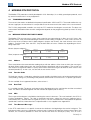
1 INTRODUCTION TO SERIAL COMMUNICATION
In a serial interface the data bits are sent sequentially through a communication channel or bus. Several
technologies use the serial communication for data transfer, including the RS232 and RS485 interfaces.
The directions that specify the RS232 and RS485 standards, however, do neither specify the character format,
nor its sequence for the data transmission and reception. Therefore, besides the interface, it is also necessary to
identify the protocol used for the communication. Among the several existent protocols, one used a lot in the
industry is the Modbus RTU protocol.
In the sequence the characteristics of the RS232 and RS485 serial interfaces available for the product will be
presented, as well as the Modbus RTU protocol for the use of those interfaces.
PLC300 | 6
Network Connections
2 NETWORK CONNECTIONS
The PLC300 programable controller has standard RS232 and RS485 interfaces. Information about the
connection and installation of the equipment to the network is presented bellow.
2.1
RS232
2.1.1
RS232 Interface Characteristics
The interface follows the EIA/TIA-232 standard.
It operates only as a slave in the Modbus RTU network, configured for network address 1.
It allows communication baud rates from 1200 up to 57600 Kbit/s.
It allows the connection between the device and the network master (point-to-point).
Maximum distance between devices: 10 meters.
2.1.2
Connector pinout
The RS232 interface is available at the XC3 connector with the following connections:
Table 2.1: RS232 connector pinout
2.1.3
Name
TX
10
RX
11
GND
Function
Data transmission (connected to
the master RX)
Data reception (connected to the
master TX)
Reference for RS232 circuit
Connection with the RS232 Network
The slave RX and TX signals must be connected to the master TX and RX, besides the connection of the
reference signal (GND).
The RS232 interface is very susceptible to interferences. For this reason, the cable used for communication
must be as short as possible – always shorter than 10 meters – and must be laid separately from the power
cables that supply other devices.
2.2
RS485
2.2.1
Pin
9
RS485 Interface Characteristics
The interface follows the EIA/TIA-485 standard.
It operates as a slave or master in the Modbus RTU network.
It allows communication baud rates from 1200 up to 57600 Kbit/s.
The interface is electrically isolated and with differential signal, which grants more robustness against
electromagnetic interference.
It allows the connection of up to 32 devices to the same segment. More devices can be connected by using
repeaters 1.
A maximum bus length of 1000 meters.
2.2.2
Connector pinout
The RS485 interface is available at the XC3 connector with the following connections:
Table 2.2: RS485 connector pinout
Pin
12
13
14
1
Name
A-Line (-)
B-Line (+)
GND
Function
RxD/TxD negative
RxD/TxD positive
0V isolated from the RS485
circuit
The limit number of devices that can be connected to the network depends also on the used protocol.
PLC300 | 7
Network Connections
2.2.3
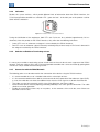
Indications
Besides the system markers, which provide different kinds of information about the RS485 interface, the
PLC300 programable controller has as bicolor LED – green and red – in the front part of the product used for
Serial Interface indication.
Figure 2.1: Indication LED of the Serial interface
During the initialization of the equipment, both LEDs are On for test for a period of approximately 500 ms
alternately. After this period, for the RS485 interface, they will make the following indications.
Green LED: turns on whenever a telegram is transmitted by the RS485 interface.
Red LED: turns on whenever a byte is incorrectly received (parity or frame error) or CRC error is detected in
the telegram received by the RS485 interface.
2.2.4
Switches to Enable to Terminating resistor
It is necessary to enable a terminating resistor at both ends of the main bus for each segment of the RS485
network. There are switches (S1) in the PLC300 programable controller that can be activated (by placing both
switches to ON) to enable the terminating resistor.
2.2.5
Connection with the RS485 Network
The following points must be observed for the connection of the device using the RS485 interface:
It is recommended the use of a shielded cable with a twisted pair of wires.
It is also recommended that the cable has one more wire for the connection of the reference signal (GND).
In case the cable does not have the additional wire, then the GND signal must be left disconnected.
The cable must be laid separately (and far away if possible) from the power cables.
All the network devices must be properly grounded, preferably at the same ground connection. The cable
shield must also be grounded.
Enable the termination resistors only at two points, at the extremes of the main bus, even if there are
derivations from the bus.
PLC300 | 8
Interface CONFIGURATION
3 INTERFACE CONFIGURATION
In order to configure the RS232 and RS485 interfaces, the following menus are provided by the Setup of the
PLC300 programmable controller:
3.1
RS232 CONFIGURATION
BAUD RATE
Range:
0 = 1200 bit/s
1 = 2400 bit/s
2 = 4800 bit/s
3 = 9600 bit/s
4 = 19200 bit/s
5 = 38400 bit/s
6 = 57600 bit/s
Default: 4
Description:
It allows programming the baud rate for the serial communication interface, in bits per second. This baud rate
must be the same for all the devices connected to the network.
PARITY
Range:
0 = no parity
1 = odd parity
2 = even parity
Default: 2
Description:
It allows programming the parity of the serial interface bytes. This configuration must be identical for all the
devices connected to the network.
STOP BITS
Range:
0 = 1 stop bit
1 = 2 stop bits
Default: 0
Description:
It allows programming the stop bits of the serial interface bytes. This configuration must be identical for all the
devices connected to the network.
NOTE!
The address of the Modbus RTU slave via RS232 interface is fixed in 1.
PLC300 | 9
Interface CONFIGURATION
3.2
RS485 CONFIGURATION
BAUD RATE
Range:
0 = 1200 bit/s
1 = 2400 bit/s
2 = 4800 bit/s
3 = 9600 bit/s
4 = 19200 bit/s
5 = 38400 bit/s
6 = 57600 bit/s
Default: 4
Description:
It allows programming the baud rate for the serial communication interface, in bits per second. This baud rate
must be the same for all the devices connected to the network.
PARITY
Range:
0 = no parity
1 = odd parity
2 = even parity
Default: 2
Description:
It allows programming the parity of the serial interface bytes. This configuration must be identical for all the
devices connected to the network.
STOP BITS
Range:
0 = 1 stop bit
1 = 2 stop bits
Default: 0
Description:
It allows programming the stop bits of the serial interface bytes. This configuration must be identical for all the
devices connected to the network.
OPERATION MODE
Range:
0 = slave
1 = master
Default: 1
Description:
Via RS485 interface, the PLC300 features two operating modes in the Modbus RTU network:
Slave: as slave of the network, it provides functions for the reading and writing of the data and markers
used in the configuration and programming in ladder of the product. For further information about this
operating mode, refer to item 5.
Master: as network master, the PLC300 provides blocks in ladder to send commands to the network
slaves, according to the configuration in these blocks. In this mode, it will not be possible to access the
data and configurations of the PLC300 via RS485 interface. Only one master can be configured to operate
on the RS485 bus. For further information about this operating mode, refer to item 7 and the documentation
of the WPS programming software.
PLC300 | 10
Interface CONFIGURATION
SLAVE ADDRESS
Range:
1 to 247
Default: 1
Description:
It allows programming the slave address used for the PLC300 in the Modbus RTU network via RS485 interface.
This address is only used if the interface is programmed in the slave mode; it has no function if the PLC300 is
programmed as network master.
PLC300 | 11
Modbus RTU Protocol
4 MODBUS RTU PROTOCOL
The Modbus RTU protocol was initially developed in 1979. Nowadays, it is a widely spread open protocol, used
by several manufactures in many equipments.
4.1
TRANSMISSION MODES
Two transmission modes are defined in the protocol specification: ASCII and RTU. The modes define the way
the message bytes are transmitted. It is not possible to use the two transmission modes in the same network.
The PLC300 programable controller uses only the RTU mode for the telegram transmission. The bytes are
transmitted in hexadecimal format and its configuration depends on the programming done by means of setup
menu.
4.2
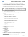
MESSAGE STRUCTURE FOR RTU MODE
The Modbus RTU structure uses a master-slave system for message exchange. It allows up to 247 slaves, but
only one master. Every communication begins with the master making a request to a slave, which answers to
the master what has been asked. In both telegrams (request and answer), the used structure is the same:
Address, Function Code, Data and CRC. Only the data field can have a variable size, depending on what is
being requested.
Master (request telegram):
Address
(1 byte)
Function
(1 byte)
Request Data
(n bytes)
CRC
(2 bytes)
Function
(1 byte)
Response Data
(n bytes)
CRC
(2 bytes)
Slave (response telegram):
Address
(1 byte)
4.2.1
Address
The master initiates the communication sending a byte with the address of the slave to which the message is
destined. When sending the answer, the slave also initiates the telegram with its own address. The master can
also send a message to the address 0 (zero), which means that the message is destined to all the slaves in the
network (broadcast). In that case, no slave will answer to the master.
4.2.2
Function Code
This field also contains a single byte, where the master specifies the kind of service or function requested to the
slave (reading, writing, etc.). According to the protocol, each function is used to access a specific type of data.
For the available list of supported functions, refer to item 5.
4.2.3
Data Field
It is a variable size field. The format and contents of this field depend on the used function and the transmitted
value. This field is described together with the function description (refer to item 5).
4.2.4
CRC
The last part of the telegram is the field for checking the transmission errors. The used method is the CRC-16
(Cycling Redundancy Check). This field is formed by two bytes; where first the least significant byte is
transmitted (CRC-), and then the most significant (CRC+). The CRC calculation form is described in the protocol
specification; however, information for its implementation is also supplied in the Appendix B.
4.2.5
Time Between Messages
In the RTU mode there is no specific character that indicates the beginning or the end of a telegram. The
indication of when a new message begins or when it ends is done by the absence of data transmission in the
network, for a minimum period of 3.5 times the transmission time of a data byte (11 bits). Thus, in case a
PLC300 | 12
Modbus RTU Protocol
telegram has initiated after the elapsing of this minimum time, the network elements will assume that the first
received character represents the beginning of a new telegram. And in the same manner, the network elements
will assume that the telegram has reached its end when after receiving the telegram elements, this time has
elapsed again.
If during the transmission of a telegram the time between the bytes is longer than this minimum time, the
telegram will be considered invalid because the programable controller will discard the bytes already received
and will mount a new telegram with the bytes that were being transmitted.
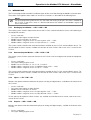
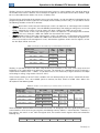
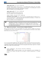
For communication rates higher than 19200 bits/s, the used times are the same as for that rate. The next table
shows us the times for different communication transmission rates:
Table 4.1: Communication rates and the time periods involved in the telegram transmission
Baud rate
1200 bits/s
2400 bits/s
4800 bits/s
9600 bits/s
19200 bits/s
38400 bits/s
57600 bits/s
T11 bits
9.167 ms
4.583 ms
2.292 ms
1.146 ms
573 µs
573 µs
573 µs
T3,5x
32.083 ms
16.042 ms
8.021 ms
4.010 ms
2.005 ms
2.005 ms
2.005 ms
= Time for transmitting one byte of the telegram.
T11 bits
Tbetween bytes = Time between bytes.
= Minimum interval to indicated beginning and end of a telegram (3.5 x T11bits).
T3,5x
PLC300 | 13
Operation in the Modbus RTU Network – Slave Mode
5 OPERATION IN THE MODBUS RTU NETWORK – SLAVE MODE
The PLC300 programable controller has the following characteristics when operated as a slave in Modbus RTU
network:
Network connection via RS232 or RS485 serial interface.
Address 2, communication rate and byte format defined by means of setup of the equipment.
It allows accessing all the markers and data used in the ladder program of the PLC300.
NOTE!
The RS232, RS485, USB and Ethernet interfaces, for using the same functions to access the data
and programming of the equipment, must not be used simultaneously to perform program download
or on-line monitoring functions of the programmable controller PLC300, because conflicts may occur
during the simultaneous access to the data.
5.1
AVAILABLE FUNCTIONS AND RESPONSE TIMES
In the Modbus specification are defined the functions used to access different types of data. In the PLC300, in
order to access those data the following services (or functions) have been made available:
Read Coils
Description: reading of bit blocks of the coil type.
Function code: 01.
Read Discrete Inputs
Description: reading of bit blocks of the discrete input type.
Function code: 02.
Read Holding Registers
Description: reading of register blocks of the holding register type.
Function code: 03.
Read Input Registers
Description: reading of register blocks of the input register type.
Function code: 04.
Write Single Coil
Description: writing in a single bit of the coil type.
Function code: 05.
Write Single Register
Description: writing in a single register of the holding type.
Function code: 06.
Write Multiple Coils
Description: writing in bit blocks of the coil type.
Function code: 15.
Write Multiple Registers
Description: writing in register blocks of the holding register type.
Function code: 16.
Read Device Identification
Description: identification of the device model.
Function code: 43.
The response time, from the end of transmission of the master until the response of the slave, varies from the
minimum time between bytes in the Modbus RTU communication to the equipment scan cycle value.
2
Programmable address only for the RS485 interface; for the RS232 interface, the address is fixed in 1.
PLC300 | 14
Operation in the Modbus RTU Network – Slave Mode
5.2
MEMORY MAP
The PLC300 programable controller has different types of data accessible through the Modbus communication.
These data are mapped at data addresses and access functions as described in the following items.
NOTE!
The WPS programming software has lists that allow the viewing of all types of markers available for
the PLC300. In these lists, there is a field for indication of the address of the Modbus register to
access the marker.
5.2.1
Reading System Marker – %SB / %SW / %SD
The reading system markers represent the data of the PLC300 used for indication of status and monitoring of
the equipment functions.
Access: read only.
Data type: input register or input discrete.
Modbus access functions: 02 and 04.
Modbus address range for access via input register: 3000 ... 4999.
Modbus address range for access via input discrete: 0 ... 15999.
The system markers related to the serial communication available for the PLC300 are described in item 8. For
the description of other markers available and function of each marker, refer to the user’s manual of the
PLC300.
5.2.2
Command System Marker – %CB / %CW / %CD
The writing system markers represent the data of the PLC300 used to configure and control the equipment
functions.
Access: read/write.
Data type: holding register or coil.
Modbus access functions: 01, 03, 05, 06, 15 and 16.
Modbus address range for access via holding register: 3000 ... 4999.
Modbus address range for access via coil. 0 ... 15999.
The system markers related to the serial communication available for the PLC300 are described in item 8. For
the description of other markers available and function of each marker, refer to the user’s manual of the
PLC300.
5.2.3
Inputs – %IB / %IW / %ID
Markers that represent the data related to the physical analog and digital inputs, available on the hardware of
the PLC300.
Access: read only.
Data type: input register or input discrete.
Modbus access functions: 02 and 04.
Modbus address range for access via input register: 5000 ... 5999.
Modbus address range for access via input discrete: 16000 ... 23999.
For the precise description of which markers are available and function of each marker, refer to the user’s
manual of the PLC300.
5.2.4
Outputs – %QB / %QW / %QD
Markers that represent the data related to the physical analog and digital outputs, available in hardware of the
PLC300.
Access: read/write.
Data type: holding register or coil.
PLC300 | 15
Operation in the Modbus RTU Network – Slave Mode
Modbus access functions: 01, 03, 05, 06, 15 and 16.
Modbus address range for access via holding register: 5000 ... 5999.
Modbus address range for access via coil. 16000 ... 23999.
For the precise description of which markers are available and function of each marker, refer to the user’s
manual of the PLC300.
5.2.5
Network Inputs – %IB / %IW / %ID
Markers that represent data related to values received through the PLC300 network interfaces. They have the
same terminology as the physical inputs, but their numbering begins from marker 2000 (example: %IB2000).
Access: read only.
Data type: input register or input discrete.
Modbus access functions: 02 and 04.
Modbus address range for access via input register: 6000 ... 7999.
Modbus address range for access via input discrete: 24000 ... 39999.
5.2.6
Network Outputs – %QB / %QW / %QD
Markers that represent data related to values transmitted through the PLC300 network interfaces. They have
the same nomenclature as the physical outputs, but their numbering begins from marker 2000 (example:
%QB2000).
Access: read/write.
Data type: holding register or coil.
Modbus access functions: 01, 03, 05, 06, 15 and 16.
Modbus address range for access via holding register: 6000 ... 7999.
Modbus address range for access via coil. 24000 ... 39999.
5.2.7
Internal Marker – %MB / %MW / %MD
General purposes markers for programming in ladder of the PLC300. They represent the global variables,
dynamically created during the development of the program on the WPS software.
Access: read/write.
Data type: holding register or coil.
Modbus access functions: 01, 03, 05, 06, 15 and 16.
Volatile markers:
Modbus address range for access via holding register: 8000 ... 27999.
Modbus address range for access via coil. 40000 ... 49999.
Retentive markers:
Modbus address range for access via holding register: 28000 ... 47999.
Modbus address range for access via coil. 50000 ... 59999.
The quantity of markers available in this area depends on the markers created on the PLC300 programming
software. In order to be able to access the desired marker, first it is necessary to create this marker and
download the user's program using the programming software.
NOTE!
The quantity of data accessible via coils and input discretes do not correspond to the entire memory
area accessible via registers. For example, if it is created a quantity of markers on memory greater
than the quantity accessible via coil (10000 bits = 1250 bytes), the additional markers can only be
accessed via holding registers.
5.3
DATA ACCESS
Each of the memory regions described above is distributed in bytes. The Modbus protocol, though, allows the
access to be performed only by bits of by registers of 16 bits. In order to access these memory regions, it is
necessary to establish the relationship between the type and numbering of the data on the PLC300 with the
PLC300 | 16
Operation in the Modbus RTU Network – Slave Mode
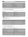
Modbus address type. The following tables show how the relationship between the numbering of the data on
the PLC300 and the address of the Modbus registers that access these data is done.
3050
...
%SB3100
...
%SB3101
...
...
Reading System Markers
Marker Number
Register Address (input register)
PLC300
Modbus
%SB3001
%SB3000
3000
%SB3003
%SB3002
3001
3050
...
%CB3100
...
%CB3101
...
...
Command System Markers
Marker Number
Register Address (holding register)
PLC300
Modbus
%CB3001
%CB3000
3000
%CB3003
%CB3002
3001
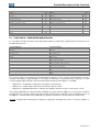
Inputs
6000
...
%IB2000
...
%IB2001
...
Register Address (input register)
Modbus
5000
5001
...
Marker Number
PLC300
%IB1
%IB0
%IB3
%IB2
6000
...
%QB2000
...
%QB2001
...
Outputs
Register Address (holding register)
Modbus
5000
5001
...
Marker Number
PLC300
%QB1
%QB0
%QB3
%QB2
28000
...
%MB40000
...
%MB40001
...
...
Internal markers (volatile and retentive)
Marker Number
Register Address (holding register)
PLC300
Modbus
%MB1
%MB0
8000
%MB3
%MB2
8001
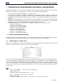
The following table illustrates how the Modbus address is calculated with access via registers, for different types
of data available for the PLC300:
Data
Description
%SW3002
%CW3030
Reading system marker which represents the scan
cycle time.
Writing system marker to set the hour of the RTC.
%IB0
Physical inputs, representing the digital inputs 1 to 8.
%MB11
Marker in volatile memory, representing a global
variable created by the user with a size of one byte.
Marker on retentive memory, representing a global
variable created by the user with a size of four bytes.
%MD40004
Data
type
Input
Register
Holding
Register
Input
Register
Holding
Register
Holding
Register
Base
address
3000
3000
5000
8000
28000
Base address
offset
2 bytes
(1 word)
30 bytes
(15 words)
0 bytes
(0 words)
11 bytes
(5 words)
4 bytes
(2 words)
Modbus
address
3001
3015
5000
byte low
8005
byte high
28002 e
28003
PLC300 | 17
Operation in the Modbus RTU Network – Slave Mode
Similarly, the access via binary data (coils or input discretes) also uses a base address plus the offset given by
the number of the marker. However, since each byte has eight bits, for each byte from the base address, eight
bits must be added to the address for access via binary data.
The data format and function in the memory area accessed, though, are not pre-defined, and depend on the
programming done on the WPS software. For example, for the memory marker %M_0, it is possible to create
the following variables on the WPS software:
%MB0: byte marker, it takes only one memory byte, and it can represent an 8-bit integer with or without
signal. In the access via registers, since the Modbus protocol allows the reading or writing access of at least
16 bits, whenever this marker is read or written, the bytes %MB0 and %MB1 are accessed.
%MW0: word marker, it takes two memory bytes, and it can represent a 16-bit integer with or without
signal. In this case, the bytes %MB0 and %MB1 are reserved for this marker.
%MD0: double marker, it takes four memory bytes, and it can represent a 32-bit integer with or without
signal. In this case, the bytes %MB0 and %MB3 are reserved for this marker. In the access by registers, it is
necessary to read or write two registers in a row, with the least significant value in the first register, so that
the four bytes will be accessed.
Table 5.1: Example of data addressing for volatile markers on the PLC300
Marker Type
Modbus addr.
Register (bit)
8000 (40000 ... 40015)
8001 (40016 ... 40031)
8002 (40032 ... 40047)
8003 (40048 ... 40063)
Byte
(%MB)
Word
(%MW)
Double
(%MD)
X
X
X
X
X
X
X
X
X
X
X
X
X
X
Similarly, it is possible to access the data using the bit access functions. In this case, a bit can be accessed
individually, or in a group of bits that represents a marker. For example, if it is defined on the WPS software a
word marker in address 8000 – %MW0 – it is possible to access this marker by using the functions of multiple
coil reading or writing, using the bits 40000 to 40015.
At the memory addresses of the PLC300, variables with size above one byte are always stored with the least
significant byte first. Thus, the available space on memory for Byte, Word or Double values follows the
description of the following table.
Table 5.2: Example of data addressing for volatiles markers on the PLC300
Marker Type
Modbus addr.
Register (bit)
8000 (40000 ... 40015)
8001 (40016 ... 40031)
8002 (40032 ... 40047)
8003 (40048 ... 40063)
Byte (%MB)
%MB0
%MB1
%MB2
%MB3
%MB4
%MB5
%MB6
%MB7
Unique value
Unique value
Unique value
Unique value
Unique value
Unique value
Unique value
Unique value
Word (%MW)
%MW0
%MW2
%MW4
%MW6
Double (%MD)
Value -signf.
Value +signf.
Value -signf.
Value +signf.
Value -signf.
Value +signf.
Value -signf.
Value +signf.
%MD0
Value -signf.
...
Value +signf.
%MD4
Value -signf.
...
Value +signf.
Since the Modbus protocol defines that in order to transmit a 16-bit register, the most significant byte must be
transmitted first, when accessing any register, the following memory address is transmitted first. Therefore, if
four registers are read in a row, from the register 8000, the content of each register will be transmitted the
following way:
1 st Register – 8000
%MB1
%MB0
2 nd Register – 8001
%MB3
%MB2
3 rd Register – 8002
%MB5
%MB4
4 th Register – 8003
%MB7
%MB6
PLC300 | 18
Operation in the Modbus RTU Network – Slave Mode
NOTE!
For the PLC300 programmable controller, the maximum size of each telegram, including address,
function, data field and CRC, must not exceed 67 bytes.
PLC300 | 19
Detailed Description of the Functions
6 DETAILED DESCRIPTION OF THE FUNCTIONS
A detailed description of the functions available in the PLC300 programable controller for the Modbus RTU is
provided in this section. In order to elaborate the telegrams it is important to observe the following:
The values are always transmitted in hexadecimal.
The address of a datum, the number of data and the value of registers are always represented in 16 bits.
Therefore, it is necessary to transmit those fields using two bytes – superior (high) and inferior (low).
The telegrams for request, as well as for response, cannot exceed 64 bytes.
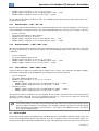
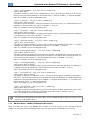
6.1
FUNCTION 01 – READ COILS
It reads the content of a group of bits (coils) that must be necessarily in a numerical sequence. This function has
the following structure for the request and response telegrams (each field represents a byte):
Request (Master)
Slave Address
Function
Address of the initial bit (high byte)
Address of the initial bit (low byte)
Number of bits (high byte)
Number of bits (low byte)
CRCCRC+
Response (Slave)
Slave Address
Function
Byte count (number of data bytes)
Byte 1
Byte 2
Byte 3
etc...
CRCCRC+
Each response bit is placed in a position of the data bytes sent by the slave. The first byte receives the eight first
bits from the initial address indicated by the master. The other bytes keep the sequence if the number of reading
bits is greater than eight. If the number of read bits is not a multiple of eight, the remaining bits of the last byte
must be filled in with zero.
Example: reading of the eight bits of the output marker 2000, mapped as coil from address 24000, considering
this marker with value 100 (64h).
Address: 1 = 01h
Number of the initial bit: 24000 = 5DC0h
Number of read bits: 8 = 0008h
Request (Master)
Field
Slave Address
Function
Initial bit (high)
Initial bit (low)
Number of bits (high)
Number of bits (low)
CRCCRC+
6.2
Response (Slave)
Value
01h
01h
5Dh
C0h
00h
08h
2Eh
5Ch
Field
Value
Slave Address
Function
Byte count
Bit status 1 to 8
CRCCRC+
01h
01h
01h
64h
50h
63h
FUNCTION 02 – READ INPUT DISCRETE
NOTE!
Function 02 – Read Input Discrete – has exactly the same structure as function 01. Only the function
code and accessible data are different.
6.3
FUNCTION 03 – READ HOLDING REGISTER
It reads the content of a group of registers that must be necessarily in a numerical sequence. This function has
the following structure for the request and response telegrams (each field represents a byte):
PLC300 | 20
Detailed Description of the Functions
Request (Master)
Slave Address
Function
Address of the initial register (high byte)
Address of the initial register (low byte)
Number of registers (high byte)
Number of registers (low byte)
CRCCRC+
Response (Slave)
Slave Address
Function
Byte count
Datum 1 (high)
Datum 1 (low)
Datum 2 (high)
Datum 2 (low)
etc...
CRCCRC+
Example: reading of the memory marker %MD0, representing a float IEEE that takes four bytes of the memory.
Considering the float value equal to 1.0 (3F800000h in representation of float IEEE).
Address: 1 = 01h
Initial register address: 8000 = 1F40h
Number of read registers: 2 = 0002h
Request (Master)
Field
Slave Address
Function
Initial register (high)
Initial register (low)
Number of registers (high)
Number of registers (low)
CRCCRC+
6.4
Response (Slave)
Value
01h
03h
1Fh
40h
00h
02h
02h
08h
Field
Value
Slave Address
Function
Byte Count
Float value (low-high)
Float value (low-low)
Float value (high-high)
Float value (high-low)
CRCCRC+
01h
03h
04h
00h
00h
3Fh
80h
F7h
CFh
FUNCTION 04 – READ INPUT REGISTER
NOTE!
Function 04 – Read Input Register – has exactly the same structure as function 03. Only the function
code and accessible data are different.
6.5
FUNCTION 05 – WRITE SINGLE COIL
This function is used to write a value for a single bit (coil). The value for the bit is represented using two bytes,
the value FF00h represents the bit in 1, and the value 0000h represents the bit in 0 (zero). It has the following
structure (each field represents a byte):
Request (Master)
Slave Address
Function
Bit address (byte high)
Bit address (byte low)
Value for the bit (byte high)
Value for the bit (byte low)
CRCCRC+
Response (Slave)
Slave Address
Function
Bit address (high byte)
Bit address (low byte)
Value for the bit (high byte)
Value for the bit (low byte)
CRCCRC+
Example: writing of the first bit of the output marker %QB0, mapped as coil from address 16000.
Address: 1 = 01h
Bit number: 16000 = 3E80h
Bit value: 1, so the value that must be written is FF00h
PLC300 | 21
Detailed Description of the Functions
Request (Master)
Field
Response (Slave)
Value
Slave Address
Function
Bit number (high)
Bit number (low)
Value for the bit (high)
Value for the bit (low)
CRCCRC+
01h
05h
3Eh
80h
FFh
00h
80h
3Ah
Field
Value
Slave Address
Function
Bit number (high)
Bit number (low)
Value for the bit (high)
Value for the bit (low)
CRCCRC+
01h
05h
1Fh
40h
FFh
00h
8Ah
3Ah
Note that for this function the slave response is an identical copy of the request made by the master.
6.6
FUNCTION 06 – WRITE SINGLE REGISTER
This function is used to write a value for a single register. It has the following structure (each field represents a
byte):
Request (Master)
Slave Address
Function
Register address (high byte)
Register address (low byte)
Value for the register (high byte)
Value for the register (low byte)
CRCCRC+
Response (Slave)
Slave Address
Function
Register address (high byte)
Register address (low byte)
Value for the register (high byte)
Value for the register (low byte)
CRCCRC+
Example: writing of the writing system marker %CB3000. Since the writing is always done by sending a 16-bit
register, the bytes mapped at addresses %CB3000 and %CB3001 will be written.
Address: 1 = 01h
Initial register address: 3000 = 0BB8h
Marker value: 50 = 0032h
Request (Master)
Field
Response (Slave)
Value
Slave Address
Function
Register (high)
Register (low)
Value (high – %CB3001)
Value (low – %CB3000)
CRCCRC+
01h
06h
0Bh
B8h
00h
32h
8Ah
1Eh
Field
Value
Slave Address
Function
Register (high)
Register (low)
Value (high – %CB3001)
Value (low – %CB3000)
CRCCRC+
01h
06h
0Bh
B8h
00h
32h
8Ah
1Eh
Note that for this function the slave response is an identical copy of the request made by the master.
6.7
FUNCTION 15 – WRITE MULTIPLE COILS
This function allows writing values for a group of bits (coils), which must be in a numerical sequence. It can also
be used to write in a single bit (each field represents a byte):
Request (Master)
Slave Address
Function
Initial bit address (high byte)
Initial bit address (low byte)
Number of bits (high byte)
Number of bits (low byte)
Byte count (number of data bytes)
Byte 1
Byte 2
Byte 3
etc...
CRCCRC+
Response (Slave)
Slave Address
Function
Initial bit address (high byte)
Initial bit address (low byte)
Number of bits (high byte)
Number of bits (low byte)
CRCCRC+
PLC300 | 22
Detailed Description of the Functions
The value of each bit being written is placed in a position of the data bytes sent by the master. The first byte
receives the first eight bits from the initial address indicated by the master. The other bytes (if the number of
written bits is greater than eight) continue the sequence. If the number of written bits is not multiple of eight, the
remaining bits of the last byte must be filled in with zero.
Example: writing of 16 bits from output marker %QW0, mapped as coil from address 16000.
Address: 1 = 01h
Number of the first bit: 16000 = 3E80h
Quantity of bits: 16 = 0010h
Value for the bits 0 to 7: 10 = 0Ah
Value for bits 8 to 15: 20 = 14h
Request (Master)
Field
Slave Address
Function
Initial bit (high)
Initial bit (low)
Number of bits
Number of bits
Byte count
Value for bits 0
Value for bits 8
CRCCRC+
Response (Slave)
Value
(high)
(low)
to 7
to 15
01h
0Fh
3Eh
80h
00h
10h
02h
0Ah
14h
24h
8Ch
Field
Value
Slave Address
Function
Initial bit (high)
Initial bit (low)
Number of bits (high)
Number of bits (low)
CRCCRC+
01h
0Fh
1Fh
40h
00h
10h
52h
07h
FUNCTION 16 – WRITE MULTIPLE REGISTERS
This function allows writing values for a group of registers, which must be in a numerical sequence. It can also
be used to write in a single register (each field represents a byte):
Request (Master)
Slave Address
Function
Initial register address (high byte)
Initial register address (low byte)
Number of registers (high byte)
Number of registers (low byte)
Byte count (number of data bytes)
Datum 1 (high)
Datum 1 (low)
Datum 2 (high)
Datum 2 (low)
etc...
CRCCRC+
Response (Slave)
Slave Address
Function
Initial register address (high byte)
Initial register address (low byte)
Number of registers (high byte)
Number of registers (low byte)
CRCCRC+
Example: writing of the writing memory marker %MD0, representing a 32-bit integer value – 4 bytes of the
memory. Considering the value to be written equal to 16909060 decimal (01020304h).
Address: 1 = 01h
Initial register address: 8000 = 1F40h
Number of registers: 2 = 0002h
PLC300 | 23
Detailed Description of the Functions
Request (Master)
Field
Slave Address
Function
Initial register (high)
Initial register (low)
Number of registers (high)
Number of registers (low)
Byte Count
Value for the integer (low-high)
Value for the integer (low-low)
Value for the integer (high-high)
Value for the integer (high-low)
CRCCRC+
6.8
Response (Slave)
Value
01h
10h
1Fh
40h
00h
02h
04h
03h
04h
01h
02h
BAh
7Bh
Field
Value
Slave Address
Function
Initial register (high)
Initial register (low)
Number of registers (high)
Number of registers (low)
CRCCRC+
01h
10h
1Fh
40h
00h
02h
47h
C8h
FUNCTION 43 – READ DEVICE IDENTIFICATION
It is an auxiliary function that allows the reading of the product manufacturer, model and firmware version. It has
the following structure:
Request (Master)
Slave Address
Function
MEI Type
Reading code
Object number
CRCCRC+
Response (Slave)
Slave Address
Function
MEI Type
Conformity Level
More Follows
Next object
Number of objects
Code of the first object
Size of the first object
Value of the first object (n bytes)
Code of the second object
Size of the second object
Value of the second object (n bytes)
etc...
CRCCRC+
This function allows the reading of three information categories: Basic, Regular and Extended, and each
category is formed by a group of objects. Each object is formed by a sequence of ASCII characters. For the
PLC300 programable controller, only basic information formed by three objects is available:
Objeto 00h – VendorName: represents the product manufacturer.
Objeto 01h – ProductCode: formed by the product code (PLC300).
Objeto 02h – MajorMinorRevision: it indicates the product firmware version, in the format ‘VX.XX’.
The reading code indicates what information categories are read, and if the objects are accessed in sequence
or individually. The PLC300 supports the codes 01 (basic information in sequence) and 04 (individual access to
the objects). The other fields are specified by the protocol, and for the PLC300 they have fixed values.
Example: reading of basic information in sequence, starting from the object 02h, from a PLC300 at address 1:
PLC300 | 24
Detailed Description of the Functions
Request (Master)
Field
Response (Slave)
Value
Slave Address
Function
MEI Type
Reading code
Object number
CRCCRC+
01h
2Bh
0Eh
01h
02h
70h
77h
Field
Slave Address
Function
MEI Type
Reading code
Conformity Level
More Follows
Next object
Number of objects
Object code
Object size
Object value
CRCCRC+
Value
01h
2Bh
0Eh
01h
81h
00h
00h
01h
02h
05h
'V1.00'
3Ch
53h
In this example the value of the objects was not represented in hexadecimal, but using the corresponding ASCII
characters instead. E.g.: for the object 02h, the value ‘V1.00’ was transmitted as being five ASCII characters,
which in hexadecimal have the values 56h ('V'), 31h ('1'), 2Eh ('.'), 30h ('0') and 30h ('0').
6.9
COMMUNICATION ERRORS
Communication errors may occur in the transmission of telegrams, as well as in the contents of the transmitted
telegrams. Depending on the type of error, the slave may or not send a response to the master.
When the master sends a message for an inverter configured in a specific network address, the product will not
respond to the master if the following occurs:
Parity bit error.
CRC error.
Timeout between the transmitted bytes (3.5 times the transmission time of a byte).
In those cases, the master must detect the occurrence of the error by means of the timeout while waiting for the
slave response. In the event of a successful reception, during the treatment of the telegram, the slave may
detect problems and send an error message, indicating the kind of problem found:
Invalid function (Error code = 1): The requested function has not been implemented for the equipment.
Invalid datum address (Error code = 2): the datum address does not exist.
Invalid datum value (Error code = 3): It occurs in the following situations:
The value is out of the permitted range.
An attempt to write in a datum that cannot be changed (reading only register/bit).
NOTE!
It is important that it be possible to identify at the master what type of error occurred, in order to be
able to diagnose problems during the communication.
In the event of any of those errors, the slave must send a message to the master indicating the type of error that
occurred. The error messages sent by the slave have the following structure:
Request (Master)
Slave Address
Function
Data
CRCCRC+
Response (Slave)
Slave Address
Function (with the most significant bit in 1)
Error code
CRCCRC+
Example: the master requests to the slave at the address 1 the writing in the register 2900 (nonexistent register):
PLC300 | 25
Detailed Description of the Functions
Request (Master)
Field
Slave Address
Function
Register (high)
Register (low)
Value (high)
Value (low)
CRCCRC+
Response (Slave)
Value
01h
06h
0Bh
54h
00h
00h
CAh
3Eh
Field
Value
Slave Address
Function
Error code
CRCCRC+
01h
86h
02h
C3h
A1h
PLC300 | 26
Operation in the Modbus RTU Network – Master Mode
7 OPERATION IN THE MODBUS RTU NETWORK – MASTER MODE
Besides the operation as a slave, the PLC300 programmable controller also allows operation as a master for the
Modbus RTU network. For this operation, it is necessary to observe the following points:
Only interface RS485 allows operation as a network master.
It is necessary to program, in product configurations, the operation mode as "Master", besides the
communication rate, parity, and stop bits, which must be the same for the whole equipment in the network.
The Modbus RTU network master does not have an address, so the address configured in the PLC300 is
not used.
Sending and receiving telegrams via RS485 interface using the Modbus RTU protocol is programmed by
using blocks in ladder programming language. It is necessary to know the available blocks and the ladder
programming software in order to be able to program the network master.
The following functions are available for the sending of requisitions by the Modbus master:
Function 01: Read Coils
Function 02: Read Discrete Inputs
Function 03: Read Holding Registers
Function 04: Read Input Registers
Function 05: Write Single Coil
Function 06: Write Single Register
Function 15: Write Multiple Coils
Function 16: Write Multiple Registers
7.1
BLOCKS TO PROGRAM THE MASTER
In order to control and monitor the Modbus RTU communication using the PLC300 programmable controller,
the following blocks were developed, and they must be used when programming in ladder.
7.1.1
MB Read Binary – Reading of Bits
Block for the reading of bits. It allows the reading of up to 128 sequential bits of the destination slave, using
functions 1 (Read Coils) and 2 (Read Discrete Inputs) in the Modbus.
It has an "Execute" block enabling input, and a "Done" output which is activated after the end of the function's
successful performance. After the positive transition of "Execute", a new telegram is sent by the Modbus RTU
master when the RS485 serial interface is free. At the operation successful end – response received from the
slave – the "Done" output is activated, remaining active while the input is active, and the received data is copied
to "Value". In case of error in the requisition performance, the "Error" output is enabled, and the error code is
put to "ErrorID".
Input:
<arg0>: “SlaveAddress” – VAR_IN: insert a variable (tag).
Types of data: BYTE
Description: Address of destination slave – 1 to 247.
<arg1>: "Function#" – VAR_IN: insert a constant.
Types of data: BYTE
Description: Reading function code: 1= "Read Coils"; 2= "Read Discrete Inputs".
PLC300 | 27
Operation in the Modbus RTU Network – Master Mode
<arg2>: "InitialDataAddress" – VAR_IN: insert a variable (tag).
Types of data: WORD
Description: Address of initial bit – 0 to 65535.
<arg3>: "NumberOfData" – VAR_IN: insert a variable (tag).
Types of data: BYTE
Description: Number of bits read in sequence starting with the initial address – 1 to 128.
<arg4>: "Timeout#" – VAR_IN: insert a constant.
Types of data: WORD
Description: Waiting time for the arrival of the response by the slave, starting with the sending by the
master – 20 to 5000 ms.
<arg5>: "Offset#" – VAR_IN: insert a constant.
Types of data: BOOL
Description: It indicates if the address of the data programmed in "InitialDataAddress#" has offset, i.e. if
the address of the data programmed in the block must be subtracted from 1 in order to send through
the Modbus network. FALSE= "Without Offset"; TRUE= "With Offset of 1".
Output:
<arg6>: "Active" – VAR_OUT: insert a variable (tag).
Types of data: BOOL
Description: Active block, requisition for reading sent to the slave and awaiting response.
Note: The variable must have writing permission.
<arg7>: "Busy" – VAR_OUT: insert a variable (tag).
Types of data: BOOL
Description: Block enabled, though resource is not available (RS485 interface busy with another
requisition), waiting for release so that the request is sent by the block. If the enabling input is removed
while the block makes that indication, the requisition is rejected.
Note: The variable must have writing permission.
<arg8>: "Error" – VAR_OUT: insert a variable (tag).
Types of data: BOOL
Description: error during requisition performance.
Note: The variable must have writing permission.
<arg9>: "ErrorID" – VAR_OUT: insert a variable (tag).
Types of data: BYTE or USINT
Description: In case of requisition error, the type of error occurred will be indicated. Possible results: 0=
"Successfully performed"; 1= "Some input data invalid" (example: Master disabled); 4= "Timeout in the
response by the slave"; 5= "Slave returned error".
Note: The variable must have writing permission.
<arg10>: "Value" – VAR_OUT: insert a variable (tag).
Types of data: BOOL[1 ... 128]
Description: Variable or array where the slave's read data will be stored.
Note: The variable must have writing permission.
7.1.2
MB Read Register – Reading of Registers
Block for the reading of 16 bit registers. It allows the reading of up to 16 sequential registers of the destination
slave, using functions 3 (Read Holding Registers) and 4 (Read Input Registers) in the Modbus.
PLC300 | 28
Operation in the Modbus RTU Network – Master Mode
It has an "Execute" block enabling input, and a "Done" output which is activated after the end of the function's
successful performance. After the positive transition of "Execute", a new telegram is sent by the Modbus RTU
master when the RS485 serial interface is free. At the operation successful end – response received from the
slave – the "Done" output is activated, remaining active while the input is active, and the received data is copied
to "Value". In case of error in the requisition performance, the "Error" output is enabled, and the error code is
put to "ErrorID".
Input:
<arg0>: "SlaveAddress" – VAR_IN: insert a variable (tag).
Types of data: BYTE
Description: Address of destination slave – 1 to 247.
<arg1>: "Function#" – VAR_IN: insert a constant.
Types of data: BYTE
Description: Reading function code: 3= "Read Holding Registers"; 4= "Read Input Registers".
<arg2>: "InitialDataAddress" – VAR_IN: insert a variable (tag).
Types of data: WORD
Description: Address of initial register – 0 to 65535.
<arg3>: "NumberOfData" – VAR_IN: insert a variable (tag).
Types of data: BYTE
Description: Number of registers read starting with the initial address – 1 to 16.
<arg4>: "Timeout#" – VAR_IN: insert a constant.
Types of data: WORD
Description: Waiting time for the arrival of the response by the slave, starting with the sending by the
master – 20 to 5000 ms.
<arg5>: "Offset#" – VAR_IN: insert a constant.
Types of data: BOOL
Description: It indicates if the address of the data programmed in "InitialDataAddress#" has offset, i.e. if
the address of the data programmed in the block must be subtracted from 1 in order to send through
the Modbus network. FALSE= "Without Offset"; TRUE= "With Offset of 1".
Output:
<arg6>: "Active" – VAR_OUT: insert a variable (tag).
Types of data: BOOL
Description: Active block, requisition for reading sent to the slave and awaiting response.
Note: The variable must have writing permission.
<arg7>: "Busy" – VAR_OUT: insert a variable (tag).
Types of data: BOOL
Description: Block enabled, though resource is not available (RS485 interface busy with another
requisition), waiting for release so that the request is sent by the block. If the enabling input is removed
while the block makes that indication, the requisition is rejected.
Note: The variable must have writing permission.
PLC300 | 29
Operation in the Modbus RTU Network – Master Mode
<arg8>: "Error" – VAR_OUT: insert a variable (tag).
Types of data: BOOL
Description: error during requisition performance.
Note: The variable must have writing permission.
<arg9>: "ErrorID" – VAR_OUT: insert a variable (tag).
Types of data: BYTE or USINT
Description: In case of requisition error, the type of error occurred will be indicated. Possible results: 0=
"Successfully performed"; 1= "Some input data invalid" (example: Master disabled); 4= "Timeout in the
response by the slave"; 5= "Slave returned error".
Note: The variable must have writing permission.
<arg10>: "Value" – VAR_OUT: insert a variable (tag).
Types of data: BYTE[1 ... 32], SINT[1 ... 32], USINT[1 ... 32], WORD[1 ... 16], UINT[1 ... 16], INT[1 ...
16], DWORD[1 ... 8], UDINT[1 ... 8], DINT[1 ... 8] or REAL[1 ... 8]
Description: Variable or array where the slave's read data will be stored.
Note: The variable must have writing permission.
NOTE!
The Modbus RTU protocol, using functions 3 and 4, allows the reading of 16 bit registers only; for
the reading of data with more than 16 bits (a REAL, for instance), it is possible to perform the
reading of multiple registers and store the value in a variable which size is bigger than 16 bits.
It is important that the quantity of read registers is compatible with the size of the variable or the
array where the data will be stored.
7.1.3
MB Write Binary – Writing of Bits
Block for the writing of bits. It allows the writing of up to 128 bits using functions 5 (Write Single Coil), and 15
(Write Multiple Coils) in the Modbus.
It has an "Execute" block enabling input, and a "Done" output which is activated after the end of the function's
successful performance. After the positive transition of "Execute", a new telegram is sent by the Modbus RTU
master when the RS485 serial interface is free. At the operation successful end – response received from the
slave – the "Done" output is activated, remaining active while the input is active. In case of error in the requisition
performance, the "Error" output is enabled, and the error code is put to "ErrorID".
Input:
<arg0>: "SlaveAddress" – VAR_IN: insert a variable (tag).
Types of data: BYTE
Description: Address of destination slave – 1 to 247.
<arg1>: "Function#" – VAR_IN: insert a constant.
Types of data: BYTE
Description: Writing function code: 5= "Write Single Coil"; 15= "Write Multiple Coils".
<arg2>: "InitialDataAddress" – VAR_IN: insert a variable (tag).
Types of data: WORD
Description: Address of initial bit – 0 to 65535.
PLC300 | 30
Operation in the Modbus RTU Network – Master Mode
<arg3>: "NumberOfData" – VAR_IN: insert a variable (tag).
Types of data: BYTE
Description: Number of bits written in sequence starting with the initial address – 1 to 128.
<arg4>: "Timeout#" – VAR_IN: insert a constant.
Types of data: WORD
Description: Waiting time for the arrival of the response by the slave, starting with the sending by the
master – 20 to 5000 ms.
<arg5>: "Offset#" – VAR_IN: insert a constant.
Types of data: BOOL
Description: It indicates if the address of the data programmed in "InitialDataAddress#" has offset, i.e. if
the address of the data programmed in the block must be subtracted from 1 in order to send through
the Modbus network. FALSE= "Without Offset"; TRUE= "With Offset of 1".
<arg6>: "Value" – VAR_IN: insert a variable (tag).
Types of data: BOOL[1 ... 128]
Description: Variable or array with the data to be written in the slave.
Output:
<arg7>: "Active" – VAR_OUT: insert a variable (tag).
Types of data: BOOL
Description: Active block, requisition for reading sent to the slave and awaiting response.
Note: The variable must have writing permission.
<arg8>: "Busy" – VAR_OUT: insert a variable (tag).
Types of data: BOOL
Description: Block enabled, though resource is not available (RS485 interface busy with another
requisition), waiting for release so that the request is sent by the block. If the enabling input is removed
while the block makes that indication, the requisition is rejected.
Note: The variable must have writing permission.
<arg9>: "Error" – VAR_OUT: insert a variable (tag).
Types of data: BOOL
Description: error during requisition performance.
Note: The variable must have writing permission.
<arg10>: "ErrorID" – VAR_OUT: insert a variable (tag).
Types of data: BYTE or USINT
Description: In case of requisition error, the type of error occurred will be indicated. Possible results: 0=
"Successfully performed"; 1= "Some input data invalid" (example: Master disabled); 4= "Timeout in the
response by the slave"; 5= "Slave returned error".
Note: The variable must have writing permission.
7.1.4
MB Write Register – Writing of Registers
Block for the writing of registers. It allows the writing of up to 16 sequential registers using function 6 (Write
Holding Register), or 16 (Write Multiple Registers) in the Modbus.
PLC300 | 31
Operation in the Modbus RTU Network – Master Mode
It has an "Execute" block enabling input, and a "Done" output which is activated after the end of the function's
successful performance. After the positive transition of "Execute", a new telegram is sent by the Modbus RTU
master when the RS485 serial interface is free. At the operation successful end – response received from the
slave – the "Done" output is activated, remaining active while the input is active. In case of error in the requisition
performance, the "Error" output is enabled, and the error code is put to "ErrorID".
Input:
<arg0>: "SlaveAddress" – VAR_IN: insert a variable (tag).
Types of data: BYTE
Description: Address of destination slave – 1 to 247.
<arg1>: "Function#" – VAR_IN: insert a constant.
Types of data: BYTE
Description: Writing function code: 6= "Write Single Register"; 16= "Write Multiple Registers".
<arg2>: "InitialDataAddress" – VAR_IN: insert a variable (tag).
Types of data: WORD
Description: Address of initial register – 0 to 65535.
<arg3>: "NumberOfData" – VAR_IN: insert a variable (tag).
Types of data: BYTE
Description: Number of registers written starting with the initial address – 1 to 16.
<arg4>: "Timeout#" – VAR_IN: insert a constant.
Types of data: WORD
Description: Waiting time for the arrival of the response by the slave, starting with the sending by the
master – 20 to 5000 ms.
<arg5>: "Offset#" – VAR_IN: insert a constant.
Types of data: BOOL
Description: It indicates if the address of the data programmed in "InitialDataAddress#" has offset, i.e. if
the address of the data programmed in the block must be subtracted from 1 in order to send through
the Modbus network. FALSE= "Without Offset"; TRUE= "With Offset of 1".
<arg6>: "Value" – VAR_IN: insert a variable (tag).
Types of data: BYTE[1 ... 32], USINT[1 ... 32], SINT[1 ... 32], WORD[1 ... 16], UINT[1 ... 16], INT[1 ...
16], DWORD[1 ... 8], UDINT[1 ... 8], DINT[1 ... 8] or REAL[1 ... 8]
Description: Variable or array with the data to be written in the slave.
Output:
<arg7>: "Active" – VAR_OUT: insert a variable (tag).
Types of data: BOOL
Description: Active block, requisition for reading sent to the slave and awaiting response.
Note: The variable must have writing permission.
PLC300 | 32
Operation in the Modbus RTU Network – Master Mode
<arg8>: "Busy" – VAR_OUT: insert a variable (tag).
Types of data: BOOL
Description: Block enabled, though resource is not available (RS485 interface busy with another
requisition), waiting for release so that the request is sent by the block. If the enabling input is removed
while the block makes that indication, the requisition is rejected.
Note: The variable must have writing permission.
<arg9>: "Error" – VAR_OUT: insert a variable (tag).
Types of data: BOOL
Description: error during requisition performance.
Note: The variable must have writing permission.
<arg10>: "ErrorID" – VAR_OUT: insert a variable (tag).
Types of data: BYTE or USINT
Description: In case of requisition error, the type of error occurred will be indicated. Possible results: 0=
"Successfully performed"; 1= "Some input data invalid" (example: Master disabled); 4= "Timeout in the
response by the slave"; 5= "Slave returned error".
Note: The variable must have writing permission.
NOTE!
The Modbus RTU protocol, using function 16, allows the writing of 16 bit registers only. For the
writing of data with more than 16 bits (one REAL, for instance), it is possible to perform the writing
of multiple registers, and use a variable which size is bigger than 16 bits as data source.
It is important that the quantity of written registers is compatible with the size of the variable or the
array where the data will be used.
7.1.5
MB Master Control/Status – Control and Status of Modbus RTU Master
Block to control and monitor the master in the Modbus RTU network. Whenever a Modbus RTU network is
assembled with the PLC300 as the network master, it is recommended to use this block in order to obtain
information on the communication state.
It has an "Execute" block enabling input, and a "Done" output which is activated after the end of the function's
successful performance. While the "Execute" enabling input is active, the input data is used and the output data
is updated. In case the input is zeroed, the input values are disregarded and the output arguments are zeroed.
Output "Done" reflects the value of the input.
Input:
<arg0>: "DisableComm" – VAR_IN: insert a constant or a variable (tag).
Types of data: BOOL
Description: It allows to disable the Modbus master. When disabling the master, the Modbus RTU
master's status counters and markers are also zeroed: 0= "Master in performance"; 1= "Disables
master".
Output:
PLC300 | 33
Operation in the Modbus RTU Network – Master Mode
<arg1>: "CommDisabled" – VAR_OUT: insert a variable (tag).
Types of data: BOOL
Description: It indicates if the master is disabled or not. It may occur by user request, or, in case the
interface is programmed to operate as the network slave: 0= "Master Enabled"; 1= "Master disabled".
Note: The variable must have writing permission.
<arg2>: "TxCounter" – VAR_OUT: insert a variable (tag).
Types of data: WORD or UINT
Description: Counter of requests sent by the network master to the slaves. It is zeroed whenever the
equipment is disconnected or the master is disabled – 0 to 65535.
Note: The variable must have writing permission.
<arg3>: "RxCounter" – VAR_OUT: insert a variable (tag).
Types of data: WORD or UINT
Description: Counter of telegrams received by the network master. It is zeroed whenever the equipment
is disconnected or the master is disabled – 0 to 65535.
Note: The variable must have writing permission.
<arg4>: "NoAnswerCounter" – VAR_OUT: insert a variable (tag).
Types of data: WORD or UINT
Description: Counter of requests by the master that were not responded by the slaves. It is zeroed
whenever the equipment is disconnected or the master is disabled – 0 to 65535.
Note: The variable must have writing permission.
<arg5>: "ErrorResponseCounter" – VAR_OUT: insert a variable (tag).
Types of data: WORD or UINT
Description: Counter of requests by the master that the slaves responded with some error response.
The error code may be obtained in the marker that indicates the code of the last detected error. It is
zeroed whenever the equipment is disconnected or the master is disabled – 0 to 65535.
Note: The variable must have writing permission.
<arg6>: "LastErrorSlaveAddress" – VAR_OUT: insert a variable (tag).
Types of data: BYTE or USINT
Description: It indicates the address of the slave in which the last communication error was detected. It
is zeroed whenever the equipment is disconnected or the master is disabled – 0 to 247.
Note: The variable must have writing permission.
<arg7>: "LastErrorResult" – VAR_OUT: insert a variable (tag).
Types of data: BYTE or USINT
Description: It indicates the operation result – timeout or error response, conforming to the block's
ERROR ID – for the slave in which the last communication error was detected. It is zeroed whenever the
equipment is disconnected or the master is disabled: 0= "Without detected error"; 4= "Timeout in the
response by the slave"; 5= "Slave returned error".
Note: The variable must have writing permission.
<arg8>: "LastErrorCode" – VAR_OUT: insert a variable (tag).
Types of data: BYTE or USINT
Description: It indicates the error code, in case the master receives an error response from some slave.
It is zeroed whenever the equipment is disconnected or the master is disabled – 0 to 255.
Note: The variable must have writing permission.
NOTE!
The data accessed through the use of this block is also available through reading and writing system
markers, as described in item 8.
7.1.6
MB Slave Status – Modbus RTU Network Slave Status
Block to monitor the slaves in the Modbus RTU network. It must be used in case it is desired to identify
problems in the communication between the master and some slave in the Modbus RTU network.
PLC300 | 34
Operation in the Modbus RTU Network – Master Mode
It has an "Execute" block enabling input, and a "Done" output which is activated after the end of the function's
successful performance. While the "Execute" enabling input is active, the input data is used and the output data
is updated at every performance of the block. Output "Done" reflects the value of the input.
Input:
<arg0>: "ErrorsToSetOffline#" – VAR_IN: insert a constant.
Types of data: BYTE
Description: It allows programming, for this block, the quantity of communication errors which the
master must identify until the communication with a network slave is considered offline. The following is
considered communication error: every request (reading or writing) a master sent to a slave and did not
receive a response, the received response had CRC error.
<arg1>: "AddressSlave1#" – VAR_IN: insert a constant.
<arg2>: "AddressSlave2#" – VAR_IN: insert a constant.
<arg3>: "AddressSlave2#" – VAR_IN: insert a constant.
<arg4>: "AddressSlave2#" – VAR_IN: insert a constant.
Types of data: BYTE
Description: It allows programming the address of up to 4 slaves which quantity of communication
errors will be monitored in order to make known if they are online or offline. In case the quantity of
sequential communication errors detected in the reading and writing blocks via Modbus reaches the
value programmed in "ErrorsToSetOffline", the respective output is activated. In case it is desired to
monitor a smaller number of slaves, any of the inputs may be set in zero: 0= "Ignores input"; 1 to 247.
Output:
<arg5>: "GeneralOffline#" – VAR_OUT: insert a variable (tag).
Types of data: BOOL
Description: If any of the outputs of the indicated slaves is activated, this output will also be activated. It
works as an OR logic between the 4 outputs of slave indication – 0 to 65535.
Note: The variable must have writing permission.
<arg6>: "Slave1Offline#" – VAR_OUT: insert a variable (tag).
<arg7>: "Slave2Offline#" – VAR_OUT: insert a variable (tag).
<arg8>: "Slave3Offline#" – VAR_OUT: insert a variable (tag).
<arg9>: "Slave4Offline#" – VAR_OUT: insert a variable (tag).
Types of data: BOOL
Description: Output activated in case the quantity of sequential communication errors for the slaves
indicated in the respective inputs reaches the value programmed in "ErrorsToSetOffline".
Note: The variable must have writing permission.
PLC300 | 35
System Markers for RS232 and RS485
8 SYSTEM MARKERS FOR RS232 AND RS485
For RS232 and RS485 serial interfaces, the following reading system markers (%S) and writing system markers
(%C) were provided for control and monitoring:
8.1
READING SYSTEM MARKERS
Modbus Master Status (RS485): reading marker set that indicates the Modbus master status, besides information for network
diagnosis.
Marker
Description
%SB3100
Status of the Modbus master:
0 = Normal operation.
1 = Mater disabled.
%SB3101
Reserved.
%SW3102
Counter of requests made by the master.
Counter incremented every time a new telegram is sent by the Modbus RTU network master. It is reset whenever it
reaches the maximum limit.
%SW3104
Counter of successfully received responses.
Counter incremented every time the master receives a successful response from a network slave. It is reset whenever it
reaches the maximum limit.
%SW3106
Counter of requests without response – timeout.
Counter incremented every time a timeout occurs for a request made by the Modbus RTU network master to a slave. It
is reset whenever it reaches the maximum limit or the interface is disabled.
%SW3108
Counter of responses received with error.
Counter incremented whenever the slave returns an error response to a request made by the Modbus RTU master. It is
reset whenever it reaches the maximum limit or the interface is disabled. Whenever this error is detected, the data for
the slave address, error type and error code will be saved on the markers %SB3110 to %SB3112.
%SB3110
Last error occurred: slave address.
%SB3111
Last error occurred: error type.
0 = No error.
4 = Timeout at the response.
5 = Slave returned error response.
It is reset whenever the interface is disabled.
%SB3112
Last error occurred: code of the received error, if the type is error response.
It is reset whenever the interface is disabled.
%SB3113
Reserved.
Status of the Modbus slave (RS485): set of reading markers that indicate the quantity of telegrams sent and received by the
Modbus RTU slave.
Marker
Description
%SW3120
Number of received telegrams. Specific for the slave mode.
%SW3122
Number of transmitted telegrams Specific for the slave mode.
8.2
WRITING SYSTEM MARKERS
Configuration of the RS232 Interface: set of writing markers to program the configurations of the RS232 interface. They are also
accessible through the Setup menu.
Marker
Description
%CB3060
Reserved.
%CB3061
Reserved.
%CB3062
Byte format:
0 = no parity, 1 stop bit
1 = odd parity, 1 stop bit
2 = even parity, 1 stop bit
3 = reserved
4 = no parity, 2 stop bits
5 = odd parity, 2 stop bits
6 = even parity, 2 stop bits
%CB3063
Baud rate for RS232:
0 = 1200 bit/s
1 = 2400 bit/s
2 = 4800 bit/s
3 = 9600 bit/s
4 = 19200 bit/s
5 = 38400 bit/s
6 = 57600 bit/s
PLC300 | 36
System Markers for RS232 and RS485
Configuration of the RS485 Interface: set of writing markers to program the configurations of the RS485 interface. They are also
accessible through the Setup menu.
Marker
Description
%CB3068
Serial address (slave modo) 1 ... 247.
%CB3069
Operation mode:
0 = Modbus RTU slave.
1 = Modbus RTU master.
%CB3070
Byte format:
0 = no parity, 1 stop bit
1 = odd parity, 1 stop bit
2 = even parity, 1 stop bit
3 = reserved
4 = no parity, 2 stop bits
5 = odd parity, 2 stop bits
6 = even parity, 2 stop bits
%CB3071
Baud rate for RS485:
0 = 1200 bit/s
1 = 2400 bit/s
2 = 4800 bit/s
3 = 9600 bit/s
4 = 19200 bit/s
5 = 38400 bit/s
6 = 57600 bit/s
Control of the Modbus Master (RS485): set of writing markers for control of the Modbus master.
Marker
Description
%CW3100
Control of the Modbus master:
0 = Normal operation.
1 = Disable interface.
PLC300 | 37
Appendices
I. APPENDICES
APPENDIX A. ASCII TABLE
Table I.1: ASCII Characters
Dec
0
1
2
3
4
5
6
7
8
9
10
11
12
13
14
15
16
17
18
19
20
21
22
23
24
25
26
27
28
29
30
31
Hex
00
01
02
03
04
05
06
07
08
09
0A
0B
0C
0D
0E
0F
10
11
12
13
14
15
16
17
18
19
1A
1B
1C
1D
1E
1F
Chr
NUL
SOH
STX
ETX
EOT
ENQ
ACK
BEL
BS
HT
LF
VT
FF
CR
SO
SI
DLE
DC1
DC2
DC3
DC4
NAK
SYN
ETB
CAN
EM
SUB
ESC
FS
GS
RS
US
(Null char.)
(Start of Header)
(Start of Text)
(End of Text)
(End of Transmission)
(Enquiry)
(Acknowledgment)
(Bell)
(Backspace)
(Horizontal Tab)
(Line Feed)
(Vertical Tab)
(Form Feed)
(Carriage Return)
(Shift Out)
(Shift In)
(Data Link Escape)
(Device Control 1)
(Device Control 2)
(Device Control 3)
(Device Control 4)
(Negative Acknowledgement)
(Synchronous Idle)
(End of Trans. Block)
(Cancel)
(End of Medium)
(Substitute)
(Escape)
(File Separator)
(Group Separator)
(Record Separator)
(Unit Separator)
Dec
32
33
34
35
36
37
38
39
40
41
42
43
44
45
46
47
48
49
50
51
52
53
54
55
56
57
58
59
60
61
62
63
Hex
20
21
22
23
24
25
26
27
28
29
2A
2B
2C
2D
2E
2F
30
31
32
33
34
35
36
37
38
39
3A
3B
3C
3D
3E
3F
Chr
Sp
!
"
#
$
%
&
'
(
)
*
+
,
.
/
0
1
2
3
4
5
6
7
8
9
:
;
<
=
>
?
Dec
64
65
66
67
68
69
70
71
72
73
74
75
76
77
78
79
80
81
82
83
84
85
86
87
88
89
90
91
92
93
94
95
Hex
40
41
42
43
44
45
46
47
48
49
4A
4B
4C
4D
4E
4F
50
51
52
53
54
55
56
57
58
59
5A
5B
5C
5D
5E
5F
Chr
@
A
B
C
D
E
F
G
H
I
J
K
L
M
N
O
P
Q
R
S
T
U
V
W
X
Y
Z
[
\
]
^
_
Dec
96
97
98
99
100
101
102
103
104
105
106
107
108
109
110
111
112
113
114
115
116
117
118
119
120
121
122
123
124
125
126
127
Hex
60
61
62
63
64
65
66
67
68
69
6A
6B
6C
6D
6E
6F
70
71
72
73
74
75
76
77
78
79
7A
7B
7C
7D
7E
7F
Chr
`
a
b
c
d
e
f
g
h
i
j
k
l
m
n
o
p
q
r
s
t
u
v
w
x
y
z
{
|
}
~
DEL
PLC300 | 38
Appendices
APPENDIX B. CRC CALCULATION USING TABLES
Next, a function using programming language “C” is presented, which implements the CRC calculation for the
Modbus RTU protocol. The calculation uses two tables to supply pre-calculated values of the necessary
displacement for the calculation.
/* Table of CRC values for high–order byte */
static unsigned char auchCRCHi[] = {
0x00, 0xC1, 0x81, 0x40, 0x01, 0xC0, 0x80, 0x41, 0x01, 0xC0, 0x80, 0x41, 0x00, 0xC1, 0x81,
0x01, 0xC0, 0x80, 0x41, 0x00, 0xC1, 0x81, 0x40, 0x00, 0xC1, 0x81, 0x40, 0x01, 0xC0, 0x80,
0x01, 0xC0, 0x80, 0x41, 0x00, 0xC1, 0x81, 0x40, 0x00, 0xC1, 0x81, 0x40, 0x01, 0xC0, 0x80,
0x00, 0xC1, 0x81, 0x40, 0x01, 0xC0, 0x80, 0x41, 0x01, 0xC0, 0x80, 0x41, 0x00, 0xC1, 0x81,
0x01, 0xC0, 0x80, 0x41, 0x00, 0xC1, 0x81, 0x40, 0x00, 0xC1, 0x81, 0x40, 0x01, 0xC0, 0x80,
0x00, 0xC1, 0x81, 0x40, 0x01, 0xC0, 0x80, 0x41, 0x01, 0xC0, 0x80, 0x41, 0x00, 0xC1, 0x81,
0x00, 0xC1, 0x81, 0x40, 0x01, 0xC0, 0x80, 0x41, 0x01, 0xC0, 0x80, 0x41, 0x00, 0xC1, 0x81,
0x01, 0xC0, 0x80, 0x41, 0x00, 0xC1, 0x81, 0x40, 0x00, 0xC1, 0x81, 0x40, 0x01, 0xC0, 0x80,
0x01, 0xC0, 0x80, 0x41, 0x00, 0xC1, 0x81, 0x40, 0x00, 0xC1, 0x81, 0x40, 0x01, 0xC0, 0x80,
0x00, 0xC1, 0x81, 0x40, 0x01, 0xC0, 0x80, 0x41, 0x01, 0xC0, 0x80, 0x41, 0x00, 0xC1, 0x81,
0x00, 0xC1, 0x81, 0x40, 0x01, 0xC0, 0x80, 0x41, 0x01, 0xC0, 0x80, 0x41, 0x00, 0xC1, 0x81,
0x01, 0xC0, 0x80, 0x41, 0x00, 0xC1, 0x81, 0x40, 0x00, 0xC1, 0x81, 0x40, 0x01, 0xC0, 0x80,
0x00, 0xC1, 0x81, 0x40, 0x01, 0xC0, 0x80, 0x41, 0x01, 0xC0, 0x80, 0x41, 0x00, 0xC1, 0x81,
0x01, 0xC0, 0x80, 0x41, 0x00, 0xC1, 0x81, 0x40, 0x00, 0xC1, 0x81, 0x40, 0x01, 0xC0, 0x80,
0x01, 0xC0, 0x80, 0x41, 0x00, 0xC1, 0x81, 0x40, 0x00, 0xC1, 0x81, 0x40, 0x01, 0xC0, 0x80,
0x00, 0xC1, 0x81, 0x40, 0x01, 0xC0, 0x80, 0x41, 0x01, 0xC0, 0x80, 0x41, 0x00, 0xC1, 0x81, 0x40
0x40,
0x41,
0x41,
0x40,
0x41,
0x40,
0x40,
0x41,
0x41,
0x40,
0x40,
0x41,
0x40,
0x41,
0x41,
};
/* Table of
static char
0x00, 0xC0,
0xCC, 0x0C,
0xD8, 0x18,
0x14, 0xD4,
0xF0, 0x30,
0x3C, 0xFC,
0x28, 0xE8,
0xE4, 0x24,
0xA0, 0x60,
0x6C, 0xAC,
0x78, 0xB8,
0xB4, 0x74,
0x50, 0x90,
0x9C, 0x5C,
0x88, 0x48,
0x44, 0x84,
0x04,
0xC8,
0xDC,
0x10,
0xF4,
0x38,
0x2C,
0xE0,
0xA4,
0x68,
0x7C,
0xB0,
0x54,
0x98,
0x8C,
};
CRC values for low–order byte */
auchCRCLo[] = {
0xC1, 0x01, 0xC3, 0x03, 0x02, 0xC2, 0xC6, 0x06, 0x07, 0xC7, 0x05, 0xC5, 0xC4,
0x0D, 0xCD, 0x0F, 0xCF, 0xCE, 0x0E, 0x0A, 0xCA, 0xCB, 0x0B, 0xC9, 0x09, 0x08,
0x19, 0xD9, 0x1B, 0xDB, 0xDA, 0x1A, 0x1E, 0xDE, 0xDF, 0x1F, 0xDD, 0x1D, 0x1C,
0xD5, 0x15, 0xD7, 0x17, 0x16, 0xD6, 0xD2, 0x12, 0x13, 0xD3, 0x11, 0xD1, 0xD0,
0x31, 0xF1, 0x33, 0xF3, 0xF2, 0x32, 0x36, 0xF6, 0xF7, 0x37, 0xF5, 0x35, 0x34,
0xFD, 0x3D, 0xFF, 0x3F, 0x3E, 0xFE, 0xFA, 0x3A, 0x3B, 0xFB, 0x39, 0xF9, 0xF8,
0xE9, 0x29, 0xEB, 0x2B, 0x2A, 0xEA, 0xEE, 0x2E, 0x2F, 0xEF, 0x2D, 0xED, 0xEC,
0x25, 0xE5, 0x27, 0xE7, 0xE6, 0x26, 0x22, 0xE2, 0xE3, 0x23, 0xE1, 0x21, 0x20,
0x61, 0xA1, 0x63, 0xA3, 0xA2, 0x62, 0x66, 0xA6, 0xA7, 0x67, 0xA5, 0x65, 0x64,
0xAD, 0x6D, 0xAF, 0x6F, 0x6E, 0xAE, 0xAA, 0x6A, 0x6B, 0xAB, 0x69, 0xA9, 0xA8,
0xB9, 0x79, 0xBB, 0x7B, 0x7A, 0xBA, 0xBE, 0x7E, 0x7F, 0xBF, 0x7D, 0xBD, 0xBC,
0x75, 0xB5, 0x77, 0xB7, 0xB6, 0x76, 0x72, 0xB2, 0xB3, 0x73, 0xB1, 0x71, 0x70,
0x91, 0x51, 0x93, 0x53, 0x52, 0x92, 0x96, 0x56, 0x57, 0x97, 0x55, 0x95, 0x94,
0x5D, 0x9D, 0x5F, 0x9F, 0x9E, 0x5E, 0x5A, 0x9A, 0x9B, 0x5B, 0x99, 0x59, 0x58,
0x49, 0x89, 0x4B, 0x8B, 0x8A, 0x4A, 0x4E, 0x8E, 0x8F, 0x4F, 0x8D, 0x4D, 0x4C,
0x85, 0x45, 0x87, 0x47, 0x46, 0x86, 0x82, 0x42, 0x43, 0x83, 0x41, 0x81, 0x80, 0x40
/* The function returns the CRC as a unsigned short type */
unsigned short CRC16(puchMsg, usDataLen)
unsigned char *puchMsg;
/* message to calculate CRC upon
unsigned short usDataLen;
/* quantity of bytes in message
{
unsigned char uchCRCHi = 0xFF;
/* high byte of CRC initialized
unsigned char uchCRCLo = 0xFF;
/* low byte of CRC initialized
unsigned uIndex;
/* will index into CRC lookup table
while (usDataLen--)
/* pass through message buffer
{
uIndex = uchCRCLo ^ *puchMsgg++; /* calculate the CRC
uchCRCLo = uchCRCHi ^ auchCRCHi[uIndex};
uchCRCHi = auchCRCLo[uIndex];
}
*/
*/
*/
*/
*/
*/
*/
return (uchCRCHi << 8 | uchCRCLo);
}
PLC300 | 39
WEG Equipamentos Elétricos S.A.
Jaraguá do Sul - SC - Brazil
Phone 55 (47) 3276-4000 - Fax 55 (47) 3276-4020
São Paulo - SP - Brazil
Phone 55 (11) 5053-2300 - Fax 55 (11) 5052-4212
[email protected]
www.weg.net