1
BusyBox User Guide
The purpose of the BusyBox is to let the Central Trigger Processor (CTP) know when the FEE’s buffers are full by
asserting a busy signal which prevents further issuing of triggers. The BusyBox and D-RORCs receive a unique
event ID from the FEE after an event. After a valid trigger sequence ends the BusyBox will ask the D-RORCs if
they have received the same event ID as the BusyBox did. If they do not reply with the same ID it means data
has not been shipped from the Fee to the D-RORC, hence, the buffer in the Fee still holds event data.
The BusyBoxes are located in the DAQ counting rom and is a FPGA based system developed at the University of
Bergen. The first of three development phases was done by Anders Rossebø. He designed the BusyBox hardware
including the 19” rack case. Then Magne Munkejord developed the firmware and PhD student Johan Alme
contributed with the Trigger Receiver Module to make the firmware complete. And finally a full test, integration
and commissioning was done by Rikard Bølgen and Magne Munkejord.
This User Guide is about the whole BusyBox system. The intention is to give newcomers to the system an
intuitive understanding without going too much in detail.
The first part of this user manual is an overview of the BusyBox. Hardware, Firmware, DCS board and
communication systems will be discussed. The second part is how to interact with everything. How to program
and read registers in the FPGA, to emulate triggers from an emulator.
For more latest firmware relase and latest discussion about the BusyBox, check out the wiki at:
https://wikihost.uib.no/ift/index.php/Busy_Box_and_related
2|Page
BusyBox User Guide
1
Table of content
1
2
TABLE OF CONTENT .............................................................................................................2
INTRODUCTION.......................................................................................................................3
2.1
2.2
3
4
4.1
4.2
5
5.1
5.2
5.3
5.4
5.5
5.6
5.7
5.8
5.9
5.10
5.11
5.12
5.13
5.14
6
6.1
6.2
6.3
6.4
6.5
7
7.1
8
8.1
8.2
8.3
8.4
9
9.1
9.2
9.3
9.4
9.5
9.6
9.7
9.8
9.9
9.10
Document History .............................................................................................................................. 3
Abstract .............................................................................................................................................. 3
SYSTEM OVERVIEW ...............................................................................................................4
BUSYBOX HARDWARE ..........................................................................................................6
Xilinx Virtex IV FPGA....................................................................................................................... 7
DCS.................................................................................................................................................... 7
BUSYBOX FIRMWARE ...........................................................................................................8
Introduction ....................................................................................................................................... 8
BusyBox top-level wrappers.............................................................................................................. 10
Module digital_clock_manager ........................................................................................................ 12
Busylogic_top Module ...................................................................................................................... 14
Reset_logic module........................................................................................................................... 14
DCS Bus Arbiter and Address Decoder ............................................................................................ 15
Receiver Module............................................................................................................................... 16
Transmitter Module.......................................................................................................................... 20
RX Memory Module ......................................................................................................................... 24
RX Memory Filter Module ............................................................................................................... 26
Trigger Receiver Module .................................................................................................................. 26
Event ID Verification Module .......................................................................................................... 29
Busy Controller Module ................................................................................................................... 34
Control and Status Registers ............................................................................................................ 35
FUNCTIONAL VERIFICATION OF THE BUSYBOX FIRMWARE ......................... 37
Introduction ..................................................................................................................................... 37
Support packages ............................................................................................................................. 38
The RCU and DRORC emulator module.......................................................................................... 40
Testbench execution flow ................................................................................................................. 41
Running the simulation in QuestaSim/ModelSim............................................................................. 43
BUSYBOX DCS BOARD........................................................................................................ 44
Setting up DCS board Firmware to use with BusyBox ..................................................................... 45
BUSYBOX COMMUNICATION.......................................................................................... 46
BusyBox - DRORC Communication................................................................................................. 46
TTCrx Communication .................................................................................................................... 49
DCS Communication ....................................................................................................................... 49
LTU Communication ....................................................................................................................... 49
GETTING STARTED WITH THE BUSYBOX ................................................................. 50
Introduction ..................................................................................................................................... 50
SVN Repository and Project Setup ................................................................................................... 50
Hardware Setup ............................................................................................................................... 51
Logging on to the DCS board ........................................................................................................... 51
RCU Shell ........................................................................................................................................ 52
Programming the FPGA .................................................................................................................. 52
Configuring the Firmware ............................................................................................................... 52
Monitoring the BusyBox registers .................................................................................................... 52
Resetting the BusyBox...................................................................................................................... 53
CTP Emulator .................................................................................................................................. 53
10
REGISTER ........................................................................................................................... 55
10.1
10.2
10.3
BusyBox Register Interface .............................................................................................................. 55
Trigger Receiver Module Register Interface ..................................................................................... 56
TPC Channel Register Interface ...................................................................................................... 58
Page |3
2
Introduction
The purpose of this document is to give users of the BusyBox an understanding of what it is, by discussing the
hardware, firmware and software which is the key components of the ALICE BusyBox system.
The scope of this technical paper and user guide will be to collect all the information necessary to understand,
use and modify the BusyBox.
2.1
Document History
Revision
number
1.0
1.1
Revision date
Summary of changes
Author
09.12.08
08.12.09
N/A
Rikard Bølgen
Magne Munkejord
•
•
•
1.2
14.09 2010
•
•
Merged into one file.
Added chapter Feil! Fant ikke
referansekilden. Feil! Fant ikke
referansekilden.. Changed document
style.
Updated some interface tables and
figures to latest firmware revision.
Updated first page
Edited layout
Kjetil Ullaland
Table 2-1: Revision history.
Package
Firmware BusyBox
Trigger Receiver Module
DCS card
Version
41
1.5
Version 2.84 BUSYBOX
Table 2-2: Firmware versions corresponding to this guide.
2.2
Abstract
ALICE is one of four large detectors situated at the collision points in the LHC at CERN. The BusyBox utilizes the
TPC, PHOS, FMD and EMCal sub-detectors and it is an FPGA based device.
It will verify the transfer of event data from the sub-detectors Front End Electronics (FEE) to the Data Acquisition
system (DAQ). The BusyBox also keeps track of free buffers in the FEE. If the buffers are full or a collision is
detected the BusyBox will flag a busy signal to a Central Trigger Processor (CTP), which halts further triggers
from being issued.
Interaction with the BusyBox is done through the DCS board, either via Ethernet or UART.
4|Page
3
BusyBox User Guide
System Overview
The BusyBox is a part of the data acquisition in four of the ALICE sub-detectors, namely: TPC, PHOS, FMD and
EMCal. The latter is currently in development.
There are some minor differences between the BusyBoxes for each sub-detector because of the different
numbers of D-RORCs they use.
Detector
TPC
PHOS
FMD
EMCal
D-RORCS
216
20
24
3
Panel height
5 units
1 unit
1 unit
1 unit
Table 3-1: Number of D-RORCs per detector
Data acquisition in ALICE is trigger based and is controlled by a Central Trigger Processor (CTP). The CTP
distributes a trigger sequence starting with a L0 trigger when it senses a collision. Then, depending on the
quality of the collision a L1 followed by an L2a or L2r trigger is issued by the CTP via the LTU.
The TPC FEE starts buffering data upon receiving a L1 trigger and PHOS a L0 trigger. The FEE on the four subdetectors can buffer 4 or 8 events depending on number of samples configured.
So, the BB has two main tasks, keep track of available buffers and maintain a past-future protection. If the
buffers are full or a L1 trigger is issued the BusyBox asserts a busy signal to the CTP, which will halt further
triggers. The busy is then removed if these conditions are no longer true.
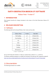
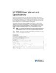
The BusyBox has no direct communication with the FEE and keeps track of available buffers by communicating
with the D-RORCs. The Trigger System sends triggers to the BusyBox and the FEE. Figure 3-1 below illustrates
the BusyBox place in the readout chain.
Page |5
Figure 3-2: Illustration of the data flow for the BusyBox system. The BusyBox and D-RORCs are placed in the counting
rooms above the experiment hall.
6|Page
4
BusyBox User Guide
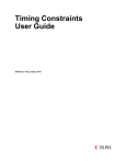
BusyBox Hardware
This chapter discusses the hardware and some key components.
Figure 4-1 BusyBox PCB
Page |7
#
1
2a
2b
3
4
5
6
Type
LED indicators
LEMO contact
LEME contact
LED indicators
RJ-45 contact
Mezzaine connectors
Resistors
Description
Indicates numbers of buffers used
LVDS busy signal from FPGA 1
LVDS busy signal from FPGA 1
7
8a
8b
9
FPGA 1
FPGA 2
Xilinx Virtex IV
Xilinx Virtex IV (TPC only)
Connector for digital analyzer. Also serves as inter connect between
FPGAs
Connectors for DCS board
Connector for external power supply. Power supply: 5V, 12 A
SelectMAP resistor for pull-ups/pulldowns and thevenin termination of
clock (CCLK).
GND, 1.2V, 2.5V and 3.3V output
FPGA2 configuration resistors. Sets the configuration mode to 8bit
SelectMAP slave.
PTH05000W voltage regulators from Texas Instruments
Standard JTAG access port. Used for configuration and debug.
BUG: SelectMAP CCLK must be cut at certain point on PCB to prevent
ringing.
10
11
12
DCS board
Power supply connector
13
14
Pin connectors
15abc
16
17
Voltage regulator
Test point JTAG interface
Test point SelectMap
interface
RJ-45 contacts for D-RORCs
Mezzaine card holders to additional RJ-45 connectors
FPGA1 configuration resistors. Sets the configuration mode to 8bit
SelectMAP slave.
Table 4-1: List of components on the PCB.
4.1
Xilinx Virtex IV FPGA
The BusyBox use the Virtex-4 LX-40 with the ff1148 package from Xilinx. There are 640 user programmable I/O
pins that support LVDS 2.5 standard used to communicate with the D-RORCs. The Virtex-4 can run on clock
speeds up to 500 MHz, store 18 Kbits in 96 BRAM modules and has DCM to provide flexible clocking and
synchronization.
A “Multiple device SelectMap bus” is used to program the FPGAs, since two FPGAs can be used with different
firmware. Linux kernel device drivers have been developed so that the Linux OS running on the DCS board can
redirect the programming bit file to the FPGA.
The BusyBox can also be programmed via JTAG interface on the PCB. When one FPGA is used a jumper on the
PCB needs to be applied to bypass the missing JTAG chain.
4.2
DCS
The DCS board was originally designed for the TRD and TPC sub-detectors, but because it was very versatile it
has been adapted for the BusyBox and other instrumenst in ALICE experiment. It is running a lightweight version
of Linux and implements TCP/IP network protocol. The DCS board has a TTCrx chip to receive the LHC clock, first
level trigger accept and trigger messages. Each card runs a FEE server that interfaces with the system it is
connected to. Thus, it makes it possible to program the FPGA(s) and read/write registers remotely from the
control room at Point 2.
8|Page
5
BusyBox User Guide
BusyBox Firmware
This chapter discusses the functionality of the firmware and gives a description of each module with submodules. The firmware modules are described with text, pictures, entities and port details.
5.1
Introduction
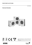
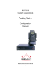
Figure 5-1: Main BusyBox firmware modules.
The firmware controls the BusyBox and executes its designed purpose based on inputs from three sources:
TTCrx, BusyBox DCS card and the D-RORCs. The above figure shows the main firmware modules of the BusyBox
and will be discussed in more detail. As mentioned before the BusyBox has two main functions: assert the busy
signal if FEE buffers are full or when a L1 trigger has been issued by the CTP.
5.1.1
An intuitive explanation of how the BusyBox firmware works
It all starts with a collision of hadrons in the LHCs ALICE detector. The CTP detects this collision and notifies the
LTU, which issues a L0 trigger to all four BusyBoxes via its optical fiber network. The L0 trigger is the start of a
sequence of triggers and ends with either an L2a or L2r trigger.
The LTU broadcasts the BC, Channel A and Channel B to the BusyBox through its fiber network and is converted
by the TTCrx chip, on the DCS card, to electrical signals. Then the information is decoded by the trigger receiver
module.
Page |9
Not all of the decoded messages are useful for the BusyBox. Hence, the trigger receiver module only extracts the
bunch count, event ID and triggers.
The triggers are forwarded to the busy controller module, which asserts the busy when a L1 trigger is received.
The bunch count and event ID is used to assure that all D-RORCs have received data from an event and with that
information in hand the BusyBox can keep track of the FEE buffers. If all D-RORCs have received event data, this
will imply that the event data have been read out from the FEE buffers. It is the busy controller module that
keeps track of the FEE buffers. FEE buffers can hold 4 or 8 events and starts buffering data on a L0 trigger (TPC
starts on a L1). So if there is a L0 trigger 1 buffer is occupied, and if all the D-RORCs have responded with the
same event ID and bunch count the EventID is OK (EIDOK). Then the event data have been read out and the
buffer is free.
A control and status register can as the name implies, control and check the status of registers in the BusyBox.
Registers in the trigger receiver module and stored data from the receiver module in the RX memory module can
also be accessed. All this is done via the FeeServer on the DCS card mounted on the BusyBox PCB.
5.1.2
•
VHDL Entity Hierarchy
busybox_fpga1_solo || busybox_fpga1 || busybox_fpga2
o busylogic_top
o ctrl_regs (Control and Status Registers)
o dcs_arbit_addr_dec (DCS Bus Arbiter and Address Decoder)
o transmitter_module(Transmitter Module)
serial_encoder
o multi_channel_receiver (Multi Channel Receiver Module)
single_channel_receiver
• serial_rx
branch_controller
backbone_controller
o rx_mem_filter
o receiver_memory_module (RX Memory Module)
rx_bram
o event_validator_top (Event ID Verification Module)
drorc_inbox_buffer
FIFOsync108x512
daq_header_extractor
eventid_control
eventid_processor
o trigger_receiver_busylogic (Trigger Receiver Module)
o busy_controller (Busy Controller)
The firmware can be implemented by using one of three different top-level wrappers. The different toplevel wrappers are necessary to adapt the firmware to fit different hardware configurations. If two
FPGAs are present then they must work in parallel and be coordinated. If only one FPGA is present it
must operate in standalone mode.
Figure 5-2 shows a graphical representation of the same information as above. In addition the IO
buffers that are instantiated in the top-level wrappers are included in the figure.
10 | P a g e
BusyBox User Guide
Figure 5-2: Module instantiation hierarchy.
5.2
BusyBox top-level wrappers
The BusyBox PCB can be fitted with one or two FPGAs depending on the number of channels required. The
different hardware configurations require slightly modified versions of the firmware at the toplevel HDL source.
A BUSY signal from FPGA2 is combined in FPGA1 among other things. There are three different toplevel HDL
files: busybox_fpga1.vhd, busybox_fpga2 and busybox_fpga1_solo. There three are different usage scenarios:
•
•
•
For BusyBoxes with 2 FPGAs mounted, FPGA1 should be programmed with firmware based on
busybox_fpga1 and FPGA with busybox_fpga2.
If the second FPGA is not going to be used then FPGA1 can be programmed with busybox_fpga1_solo, but
FPGA2 must then be programmed with a dummy configuration for the programming operation to finish
without errors.
For BusyBoxes with only one FPGA firmware based on busybox_fpga1_solo must be used.
At the toplevel HDL wrappers it is possible to specify the number of channels to be implemented. Each channel is
connected to the rest of the design through a branch. One branch controller can support up to 16 channels.
There must be enough branches to connect the number of channels specified or the implementation will fail.
P a g e | 11
5.2.1
Entity BusyBox FPGA Modules
Acts as a wrapper for each version of the three firmware versions: busybox_fpga1.vhd, busybox_fpga2.vhd and
busybox_fpga1_solo.vhd. These wrappers instantiates the BusyBox top module with the required generic
parameters and extra logic. The wrapper also adds and configures the necessary Virtex-4 IO buffers and Digital
Clock Manager (DCM) around the busylogic_top module.
busybox_fpga1
clock_lvds_P serial_tx_p
clock_lvds_N serial_tx_n
areset_n
dcs_data
serialB_in
dcs_ack_n
L1Trig_P
BUSY_1
L1Trig_N
BUSY_2
serial_rx_p
leds
serial_rx_n
dcs_adr
dcs_strobe_n
dcs_RnW
intercon_busy
TTXrx_ready
busybox_fpga2
clock_lvds_P
clock_lvds_N
areset_n
serialB_in
L1Trig_P
L1Trig_N
serial_rx_p
serial_rx_n
dcs_adr
dcs_strobe_n
dcs_RnW
TTXrx_ready
serial_tx_p
serial_tx_n
dcs_data
dcs_ack_n
intercon_busy
busybox_fpga1_solo
clock_lvds_P
clock_lvds_N
areset_n
serialB_in
L1Trig_P
L1Trig_N
serial_rx_p
serial_rx_n
dcs_adr
dcs_strobe_n
dcs_RnW
TTXrx_ready
serial_tx_p
serial_tx_n
dcs_data
dcs_ack_n
BUSY_1
BUSY_2
leds
Figure 5-3: Entity for BusyBox FPGA modules.
•
BUSY1 and BUSY2 outputs only exist on FPGA1. These outputs are the same logical signal.
12 | P a g e
•
BusyBox User Guide
Busybox_fpga1 wrapper takes busy input (intercon_busy) from FPGA2 and combines it with its own
BUSY output through an OR gate.
Generic name
num_of_channels
Type
natural
Legal range
0 to 119
Default value
119
num_of_branches
natural
1 to 8
8
Description
Specifies the number of channels (-1)
that will be instantiated at compiletime.
Specifies number of branches at
compile-time. Each branch can connect
16 serial receiver channels.
Table 5-1: Generics at the HDL top-level wrappers.
BusyBox wrapper
busybox_fpga1
busybox_fpga2
busybox_fpga1_solo
num_of_channels
119
96
39
num_of_branches
8
6
3
Table 5-2: Default values for generic parameters for BusyBox wrappers.
Port Name
clock_lvds_P
clock_lvds_N
areset_n
serialB_in
L1Trig_P
L1Trig_N
serial_rx_p
serial_rx_n
dcs_adr
dcs_strobe_n
dcs_RnW
intercom_busy
serial_tx_p
serial_tx_n
dcs_data
dcs_ack_n
BUSY_1
BUSY_2
leds
Direction
Input
Input
Input
Input
Input
Input
Input
Input
Input
Input
Input
2
Input/Output
Output
Output
Bidirectional
Output
3
Output
2
Output
2
Output
# Bit
1
1
1
1
1
1
1
120
120
16
1
1
1
1
1
16
1
1
1
13
Description
std_logic;
std_logic;
std_logic;
std_logic;
std_logic;
std_logic;
std_logic_vector(0 to num_of_channels);
std_logic_vector(0 to num_of_channels);
std_logic_vector(15 downto 0);
std_logic
std_logic;
std_logic;
std_logic_vector(0 to num_of_channels)
std_logic_vector(0 to num_of_channels)
std_logic_vector(15 downto 0)
std_logic;
std_logic;
std_logic;
std_logic_vector(1 to 13);
Table 5-3: I/O details for BusyBox FPGA Modules.
5.3
Module digital_clock_manager
This core has been generated by the Xilinx tool Architect Wizard available through the CoreGen GUI. It a single
DCM configured to deskew and output two clock signals generated from the incoming clock. The incoming clock
from the DCS board is approximately 40 MHz. The DCM multiplies this clock signal by 5 to generate a 200 MHz
output used in the design. The 40MHz and 200 MHz are routed to global clock buffers that drive global clock
nets to distribute the clock signals around the chips.
The DCM is setup in a system synchronous configuration. This means that the clock is fed back to the DCM after
it has gone through the clock distribution network. The DCM will regulate the phase of its output clocks so that
1
Number of channels implemented is configurable.
This is an input on FPGA1 and an output on FPGA1. It does not exist in the busybox_fpga1_solo wrapper.
3
Only exists on FPGA1.
2
P a g e | 13
the feedback clock’s rising edge and incoming’s clock rising edge are aligned. This is done to compensate for the
delay of the clock distribution network in the chip. This configuration ensures that the chip/FPGA is clocked
synchronously with the rest of the system (other synchronous elements).
During startup of the FPGA (right after the configuration data has been loaded) the internal circuits of the DCM
will try to lock on the incoming clock signal. This is an operation that might take several thousand clock cycles to
complete and may fail if the incoming clock contains glitches and/or sporadic behavior. The clocks supplied by
the DCM are not reliable until the DCM has acquired lock. A dedicated output signal named “lock” from the
DCM indicates when lock has been acquired. This signal is forwarded to the reset logic which will hold the
design in reset until the lock signal is deasserted.
The wizard that generates the DCM core does not support enabling of the DIFF_TERM attribute of the
differential global clock input buffer (IBUFGDS). Therefore the clock input buffer is disabled in the wizard and
instead the input buffer is instantiated in the BusyBox top-level wrapper files where the DIFF_TERM attribute is
enabled. This is essential for the design to operate reliable, otherwise the DCM may not lock on the incoming
reference clock and the internal clock signals will be full of glitches and spurious behavior.
NOTE: The differential termination could/can also be enabled by constraints in the User Constraints File (UCF).
Figure 5-4: Entity for digital_clock_manager
14 | P a g e
5.4
BusyBox User Guide
Busylogic_top Module
The busylogic_top module is the common top level for all three firmware versions. It has a structural
architecture where all main modules are instantiated and connected.
5.4.1
Entity for busylogic_top Module
Figure 5-5: Entity for BusyBox top module.
Port Name
clk200
clk40
areset
serialB_in
L1Trig_in
channels_in
dcs_addr
dcs_strobe_n
dcs_RnW
ttcrx_rdy
buffers_used
channels_out
busy_out
dcs_ack_n
dcs_data
Direction
Input
Input
Input
Input
Input
Input
Input
Input
Input
Input
Output
Output
Output
Output
In/Out
# Bit
1
1
1
1
1
120
16
1
1
1
4
120
1
1
16
Description
std_logic;
std_logic;
std_logic;
std_logic;
std_logic;
std_logic_vector(0 to num_of_channels);
std_logic_vector(15 downto 0);
std_logic;
std_logic;
std_logic;
std_logic_vector(3 downto 0);
std_logic_vector(0 to num_of._channels);
std_logic;
std_logic;
std_logic_vector(15 downto 0);
Table 5-4:I/O details for BusyBox Top Module.
5.5
Reset_logic module
This module implements some simple reset logic to generate proper reset signals to the design. The reset signals
will be asserted asynchronously whenever the DCM’s locked signal is low. In other words, the design will not
activate before the DCM locks on the incoming clock. After the DCM achieves lock it will assert the lock signal.
The reset logic implements a shift register that is used to delay a synchronous release of the reset signals.
Reset signals for both clock domains are generated. This is done to let the synthesis tools employ “register
duplication” to reduce fanout and routing delay of the resets in both clock domains.
P a g e | 15
Generic Name
g_rst_length
Type
natural
Comment
Sets the time in number of clock (clk40) cycles before the resets are released.
Table 5-5: Tabel of generic parameters for reset_logic module.
Port Name
clk200
clk40
clk_lock
rst200
rst40
Direction
in
in
in
out
out
Type
std_logic
std_logic
std_logic
std_logic
std_logic
Comment
200 MHz clock input
40 MHz clock input
acts active low asynchronous reset
synchronous reset for the 200 MHz clock domain
synchronous reset for the 40 MHz clock domain
Table 5-6: IO table for reset_logic module.
5.6
DCS Bus Arbiter and Address Decoder
The DCS bus arbiter and address decoder module is an asynchronous 16 bit data/address handshake protocol
for communication between the FPGA and DCS board. This protocol is used to read and write registers in the
BusyBox firmware. The MSB of the 16 bits DCS bus address selects which FPGA to communicate with. Then each
module can be accessed with the next three bits and the remaining bits are used to target specific sub-module
registers.
FPGA address
15
Module address
14 – 12
Sub module address
11 – 0
Table 5-7: Bit-mapping of DCS bus address.
5.6.1
Entity DCS bus arbiter and address decoder
Figure 5-6: Entity for DCS Bus Arbiter and Address Decoder.
Generic name
c_fpga_id
Type
std_logic
Comment
This bit sets the slave FPGA MSB address. ‘0’ for FPGA1 or ‘1’ for FPGA2.
Table 5-8: Generic parameters for dcs_arbit_addr_dec
Port Name
clk40
dcs_strobe_n
Direction
Input
Input
# Bit
1
1
dcs_RnW
dcs_addr
Input
Input
1
16
dcs_data
dcs_ack_n
Inout
Output
16
1
Description
std_logic; the clk40 frequency is 40.08 MHz
std_logic; the asynchronous handshake is done with STROBE_N
from the DCS board.
std_logic; ‘1’ read and ‘0’ write.
std_logic_vector(15 downto 0); address module and submodule
register.
std_logic_vector(15 downto 0); bi-directional data line.
std_logic; the asynchronous handshake is done with ACK_N from
the busy board.
16 | P a g e
BusyBox User Guide
module_data_array
Output
7
module_en_array
Output
7
module_address
module_RnW
Output
Output
12
1
std_logic_vector(0 to num_of_modules-1); communication with
modules.
std_logic_vector(0 to num_of_modules-1); communication with
modules.
std_logic_vector(11 downto 0); communication with modules.
std_logic; communication with modules.
Table 5-9:I/O details for DCS Bus Arbiter and Address Decoder.
5.7
Receiver Module
Serial data from the D-RORCs are handled by the receiver module and up to 120 single channels can be
implemented in one FPGA.
Detector
TPC
PHOS
FMD
EMCal
# Channels on FPGA 1
120
20
24
3
# Channels on FPGA 2
96
N/A
N/A
N/A
Table 5-10: Numbers of channels per detector pr FPGA.
In order to implement error tolerance, the 48 bit word from the D-RORC is sampled in a 16 bit data frame. A
state machine in the Single Channel Receiver module reads out the data word, one word after another, when
the serial decoder flags that data is ready to be sent. A countdown timer in the state machine discards the data
if the strict timing between data readout is compromised. In that case the next word is then considered the first
in the readout sequence of three words.
If all three words have been read out successfully, and no parity errors and timeouts were found, the state
machine will send the data to a multiplexer tree.
Up to sixteen Single Channel Receivers can be connected to a Branch Controller module. The Branch Controller
buffers data from the Single Channel Receivers and stops further buffering until data have been read out by the
Backbone Controller. The Backbone Controller may have up to eight Branch Controllers and the concept is
illustrated in
P a g e | 17
.
Figure 5-7: Architecture of multi channel receiver.
5.7.1
Receiver Module VHDL Entity Hierarchy
1) Multi Channel Receiver
18 | P a g e
•
•
•
5.7.2
BusyBox User Guide
Single Channel Receiver
∗ Serial Decoder
Branch Controller
Backbone Controller
Entity Multi Channel Receiver Module
The Multi Channel Receiver module has structural architecture that instantiates and connects the correct
numbers of single channel receivers and branch controllers. The single channel serial receivers are connected to
branch controllers and the branch controllers are then connected to the backbone controller. See Figure 5-8. The
number of channels and number of branches to instantiate is defined through generics.
Figure 5-8: Entity for Channel Receiver Module.
Port Name
clk200
areset
serial_channel_in
Direction
Input
Input
Input
# Bit
1
1
120
CHEN_vector
Input
120
data_out
channel_out
Output
Output
48
8
write_req
Output
1
Description
std_logic; the clk200 frequency is 200 MHz.
std_logic; asynchronous reset
std_logic_vector(0 to num_of_channels); LVDS serial channels
from D-RORCs
std_logic_vector(0 to num_of_channels); CHEN vector is a
register in the Control and Status Register module , one bit set
or disable channels.
std_logic_vector(47 downto 0); 48 bit data from D-RORCs
std_logic_vector(7 downto 0); toggles the data from the
different channels to be outputted
std_logic; ‘1’ D-RORC data ready to send
Table 5-11: I/O details for Channel receiver Module.
5.7.3
Entity Single Channel Receiver
A state machine checks for parity errors and make sure that the 16 bit words from the serial decoder is within
the allowed time limit. Three 16 bit words are concatenated to a 48 bit message and stored temporary in three
different registers. If the registers are not read out fast enough they will be overwritten.
Figure 5-9: Entity for Single Channel Receiver.
P a g e | 19
Port Name
clk200
rst200
enable
serial_in
data_out
read_ack
data_av
Direction
Input
Input
Input
Input
Output
Input
Output
# Bit
1
1
1
1
48
1
1
Description
std_logic; the clk200 frequency is 200 MHz.
std_logic; synchronous rest.
std_logic;
std_logic; data bit from serial decoder.
std_logic_vector(47 downto 0); 48 bit data from D-RORC
std_logic;
std_logic;
Table 5-12: I/O details for Single Channel Receiver.
20 | P a g e
5.7.4
BusyBox User Guide
Entity Serial Decoder
Figure 5-10: Entity for Serial Decoder.
Port Name
clk200
rst200
enable
serial_in
parity_error
data_av
data_out
Direction
Input
Input
Input
Input
Output
Output
Output
# Bit
1
1
1
1
1
1
16
Description
std_logic; the clk200 frequency is 200 MHz.
std_logic; synchronous reset
std_logic;
std_logic; serial signal from D-RORC
std_logic;
std_logic;
std_logic_vector(15 downto 0); data from D-RORC
Table 5-13: I/O details for Serial Decoder.
If the Serial Decoder is enabled it listens to the transmission line for serial data. Each data word is packed into a
frame and encoded on the serial signal as illustrated in
Figure 5-11. When the line is idle it pulled to logic 1. A frame starts with two start bits to create 1-0 transition.
The decoder looks for this transition to lock on to the data frame. Each bit is sampled 5 times. This is necessary
to detect the bit phase of the incoming serial bit stream. Once the 1-0 transition of the start bits are found a
state machine in the decoder triggers and start capturing data. The state machine picks the sample that is
believed to be the middle of each bit by counting samples at the local clock rate. After 16 data bits have been
sampled, a parity bit and a stop bit are sampled. Both must have the correct logic value before the frame is
accepted and data forwarded. The parity bit is a even parity generated by XOR’ing the data bits as they are
received. The stop bit is always logic 0.
Figure 5-11: Encoding of serial data on transmission line.
5.7.5
Entity Branch Controller
The Branch Controller reads data from up to 16 Single Channels Receiver’s and feed the data to the backbone
controller. It scans the receivers for data available flag and copies the data to a buffer when the flag is raised.
The branch controller will hold until the Backbone Controller has verified that it has read the message.
P a g e | 21
Figure 5-12: Entity for Branch Controller.
Port Name
clk200
Rst200
data_in_array
data_av_vector
read_ack
read_ack_vector
data_out
count_out
Direction
Input
Input
Input
Input
Input
Output
Output
Output
# Bit
1
1
16
16
1
16
48
4
data_av
Output
1
Description
std_logic; the clk200 frequency is 200 MHz.
std_logic; synchronous reset
receiver_busy_array(0 to 15);
std_logic_vector(0 to 15); ‘1’ when data is available
std_logic; from backbone controller
std_logic_vector(0 to 15);
std_logic_vector(47 downto 0); 48 bit data
std_logic_vector(3 downto 0); counter to keep track of serial
channel being scanned
std_logic; ‘1’ when data from serial receiver is ready to be sent
Table 5-14: I/O details for Branch Controller.
5.7.6
Entity Backbone Controller
The Backbone Controller reads data from up to 8 Branch Controller’s and writes the data to the RX Memory
module and the D-RORC inbox buffer in the Event Validator Top module.
Figure 5-13: Entity for Backbone Controller.
Port Name
clk200
rst200
data_in_array
count_in_array
read_ack_vector
data_out
count_out
data_av_vector
write_req
Direction
Input
Input
Input
Input
Output
Output
Output
Output
Output
# Bit
1
1
8
8
8
48
8
8
1
Table 5-15: I/O details for Backbone Controller.
5.8
Transmitter Module
Description
std_logic; the clk200 frequency is 200 MHz.
std_logic; synchronous reset
receiver_bus_array(0 to 7); work.busylogic_pkg
count_array(0 to 7); work.busylogic_pkg
std_logic_vector(0 to 7);
std_logic_vector(47 downto 0); 48 bit data
std_logic_vector(7 downto 0);
std_logic_vector(0 to 7);
std_logic;
22 | P a g e
BusyBox User Guide
The transmitter module transmits serial data to the D-RORCs and consists of a controller, a serial decoder and a
masking vector. A message register and a channel register are available for the DCS bus module and Event ID
Verification module. Data from the message register will be loaded into the serial encoder and the masking
vector will be created based on the channel number in the channel register. The masking vector lets the Event ID
Verification module and DCS bus module select which channels to enable or disable. The controller handles
requests from the Event ID Verification module and DCS bus module to prevent communication conflicts.
A state machine in the serial encoder module sends a 16 bit word to the PISO (Parallell In –Serial Out) module by
request from the controller.
Figure 5-14: Transmitter system. From [Magne]
The transmitter module will request eventIDs from the D-RORCs. The request is a 16 bit word and is sent to all
D-RORCs.
15 – 12
Command type
11 – 8
Request ID
7-0
Unused
Table 5-16: Bit map for Trigger module request.
Command type
Bit Code
Description
P a g e | 23
Request Event ID
Resend last message
Force pop Event ID
Force Request ID
0100
0101
0110
0111
Request an Event ID from the D-RORC.
Command the D-RORC to re-transmit the last message sent.
Command the D-RORC to pop one Event ID from its local queue.
Command the D-RORC to store the attached Request ID.
Table 5-17: Request commands.
5.8.1
•
Transmitter module VHDL Entity Hierarchy
Transmitter module
o Serial encoder
The Transmitter module is initiating the serial encoder and setting the masking vector.
5.8.2
Entity Transmitter module
The Transmitter module is initiating the serial encoder and setting the masking vector. A 16 bit register can be
accessed from the DCS bus as shown in figure 5-15. The register contains a message register and a channel
register.
temp_dcs_data
dcs_tx_channel
dcs_tx_data
15 – 8
7-0
Table 5-18: Bit map for DCS data.
The channel register selects which channel to be masked and unmasked the other channels. If the value in the
channels register does not specify a specific channel, all channels are unmasked and the message is
broadcasted to all channels. A flag is raised in to indicate that data are available to be written from the DCS
board to the message register. A state machine, see figure 5-16, in the controller sees the flag and starts
loading data into the serial encoder and sets the masking vector. The flag is removed and the procedure is
executed.
The Event ID module sends a request to the transmitter module and the request is granted if there is no pending
flag from the DCS bus. The controller loads data and the masking vector from the EventID module.
Messages are Hamming coded in the Transmitter module in an 8:4 code applied to the 4 bit command word and
request ID. The receiver (D-RORC) will discard data if it finds any errors. The Hamming function is in the
busylogic_pkg.
24 | P a g e
Bit
position
P1
P2
P3
P4
8
P4
P4
BusyBox User Guide
7
D4
X
X
X
X
6
D3
X
X
X
5
D2
X
4
P3
X
X
P3
X
3
D1
X
X
2
P2
X
X
1
P1
P1
P2
X
Table 5-19: Hamming code table
Figure 5-17: State diagram for TX controller
Figure 5-18: Entity for Transmitter Module.
P a g e | 25
Port Name
rst40
clk200
clk40
fw_req
fw_data
fw_mask
module_en
module_rnw
module_data_in
module_address
serial_channels_out
fw_ack
module_data_out
Direction
Input
Input
Input
Input
Input
Input
Input
Input
Input
Input
Output
Output
Output
# Bit
1
1
1
1
8
120
1
1
16
12
120
1
16
Description
std_logic; synchronous reset
std_logic; the clk200 frequency is 200 MHz
std_logic; the clk40 frequency is 40.08 MHz
std_logic;
std_logic_vector(7 downto 0);
std_logic_vector(0 to num_of_channels);
std_logic;
std_logic;
std_logic_vector(15 downto 0);
std_logic_vector(11 downto 0);
std_logic_vector(0 to num_of_channels);
std_logic;
std_logic_vector(15 downto 0); 16 bit request data to DRORCs
Table 5-20: I/O details for Transmitter Module.
5.8.3
Entity Serial Encoder
Figure 5-19: Entity for Serial Encoder.
Port Name
rst40
clk40
data_in
data_wren
busy_out
serial_out
Direction
Input
Input
Input
Input
Output
Output
# Bit
1
1
1
1
1
1
Description
std_logic; synchronous reset
std_logic; ; the clock_in frequency is 200 MHz
std_logic_vector;
std_logic;
std_logic;
std_logic;
Table 5-21: I/O details for Serial Encoder.
5.9
RX Memory Module
The BusyBox can store up to 1024 D-RORC messages from the Receiver module in the RX Memory module. Four
4
BRAM modules are instantiated in the FPGA and can be accessed from both clock domains . Data from the
Receiver module is 56 bit and is written into memory at the address given by a 10 bit counter. The DCS bus is
limited to read 16 bit at a time, and needs four read operations to get the whole word from memory. The RX
Memory module can be written to by the DCS bus for testing and verification purposes.
4
The Receiver module operates in the 200 MHz domain while the internal logic of the BusyBox runs in the 40
MHz domain.
26 | P a g e
BusyBox User Guide
Figure 5-20: Illustration of the RX Memory module. From [Magne].
5.9.1
Entity RX Memory Module
clk200
clk40
rst200
data_in
data_in_en
mem_pointer
module_data_in
module_data_out
module_address
module_rnw
module_en
Figure 5-21: Entity for RX Memory Module.
Port Name
clk200
clk40
rst200
rst40
data_in
data_in_en
mem_pointer
module_data_in
module_data_out
module_address
module_rnw
module_en
Direction
Input
Input
Input
Input
Input
Input
Output
Output
Output
Output
Output
Output
# Bit
1
1
1
1
64
1
10
16
16
12
1
1
Table 5-22: I/O details for RX Memory Module.
Description
std_logic; the clk200 frequency is 200 MHz
std_logic; the clk40 frequency is 40.08 MHz
std_logic; synchronous reset
std_logic; synchronous reset
std_logic_vector(63 downto 0);
std_logic;
std_logic_vector(9 downto 0);
std_logic_vector(15 downto 0);
std_logic_vector(15 downto 0);
std_logic_vector(11 downto 0);
std_logic;
std_logic;
P a g e | 27
5.10 RX Memory Filter Module
The RX Memory filter can be used to filter which messages from specific channels will trigger the write enable
signal form the RX Memory Module. Each message from the Receiver Module will have an 8 bit channel number
appended to it. Each individual bit of this 8 bit word can be compared with bits in a register in the RX Memory
Filter that is accessible from the DCS bus interface. The RX Memory Filter has registers with 16 bits. The first 8
bits are used to toggle matching individual bits. The last 8 bits are the bits that will be compared with the
channel number bits of the message. This feature makes it easier to see the response of only a subset of
channels in the RX Memory without disabling the other channels in the CHEN registers.
5.10.1 Entity RX Memory Filter Module
Figure 5-22: Entity for RX Memory Filter.
Port Name
pattern
match_mask
drorc_address
write_en
filtered_we
Direction
Input
Input
Input
Input
Output
# Bit
8
8
8
1
1
Description
std_logic_vector(7 downto 0);
std_logic_vector(7 downto 0);
std_logic_vector(7 downto 0);
std_logic;
std_logic;
Table 5-23: I/O details for RX Memory Filter.
5.11 Trigger Receiver Module
The optical signals from the CTP are converted to electrical signals by the TTCrx chip on the DCS board into
Channel A and Channel B. The Trigger Receiver module decodes the information and stores it in a FIFO in the
CDH (Common Data Header) format. Triggers will appear as individual signal at the module outputs.
Channel A transmits the L0 and L1 triggers. Channel B transmits the broadcast message and the individually
addressed messages. The addressed messages are decoded into the CDH format and put in a FIFO. The BusyBox
extracts the event ID (OrbitID + BunchCountID), event info and event errors from the CDH. Figure 5-23 shows an
overview of the Trigger Receiver module.
28 | P a g e
BusyBox User Guide
Figure 5-24: Block diagram of the Trigger Receiver module. From [Johan].
P a g e | 29
5.11.1 Entity Trigger Receiver Module
Figure 5-25: Entity for Trigger Receiver Module.
Port Name
clk
reset_n
L1Accept
serialBchannel
read_enable
data_in
addr
rnw
module_enable
FEE_reset
busy
cal_pre_pulse
start_of_run
end_of_run
event_reset
bunch_reset
bunchcnt_overflow
L0_trigger
L1a_trigger
L2a_trigger
L2r_trigger
L2_timeout
DAQ_header_out
read_counter_out
buffered_events
data_out
Direction
Input
Input
Input
Input
Input
Input
Input
Input
Input
Output
Output
Output
Output
Output
Output
Output
Output
Output
Output
Output
Output
Output
Output
Output
Output
Output
# Bit
1
1
1
1
1
16
12
1
1
1
1
1
1
1
1
1
1
1
1
1
1
1
33
4
4
16
Description
std_logic; the clk frequency is 40.08 MHz
std_logic;
std_logic;
std_logic;
std_logic;
std_logic_vector(15 downto 0);
std_logic_vector(11 downto 0);
std_logic;
std_logic;
std_logic; N/A
std_logic;
std_logic; N/A
std_logic; N/A
std_logic; N/A
std_logic; N/A
std_logic; N/A
std_logic; N/A
std_logic;
std_logic;
std_logic;
std_logic;
std_logic;
std_logic_vector(32 downto 0);
std_logic_vector(3 downto 0);
std_logic_vector(3 downto 0);
std_logic_vector(15 downto 0);
30 | P a g e
BusyBox User Guide
Table 5-24: I/O details for Trigger Receiver Module.
5.12 Event ID Verification Module
The Trigger Receiver module’s FIFO is constantly monitored by the Event ID Verification module. Data from an
L2a/L2r or L2 timeout trigger is stored in the CDH format in the FIFO and will be read out by the Event ID Queue
module.
The event controller then requests the Transmitter module to read out the data and send it to the D-RORCs. The
Receiver module forwards D-RORC data to the D-RORC Inbox Buffer. The Inbox operates in both frequency
5
domains and makes the data available for the Event processor, which compares the event ID.
event_validator_top
DAQ header
daq_header_extractor
TX data
The Event Processor has a register called EIDOK (Event ID OK), and together with the CHEN vector it compares
the two event IDs from the Event ID Queue module and the D-RORC Inbox buffer. If the ID matches, the
verification gate will assert an event verified signal. An overview of the ID verification model is shown in The
BusyBox has no direct communication with the FEE and keeps track of available buffers by communicating with
the D-RORCs. The Trigger System sends triggers to the BusyBox and the FEE. Figure 3-1
event valid
eventid_control
ctrl
event errors
event info
event id
event_queue
event valid
ctrl
event id
event_processor
drorc_inbox_buffer
clk200 domain
DRORC messages
clk40 domain
CHEN
DRORC
messages
Figure 5-26: Illustration of the structure of event_validator_top module.
The eventid_control block controls the flow of new eventIDs from the event_queue and DRORC messages from
the drorc_inbox_buffer to the event_processor. It is also commands the TX controller to transmit requests to the
DRORCs. The event_processor block determines when the current event has been verified/validated.
5.12.1 Event_validator_top VHDL Entity Hierarchy
•
5
Event_validator_top
o i_daq_header_extractor: daq_header_extractor
o i_event_queue: FIFOsync108x512(Core)
o i_eventid_control: eventid_control
o i_event_processsor : event_processor
The Receiver module operates in the 200 MHz domain while the internal logic of the verification module runs
in the 40 MHz domain.
P a g e | 31
o
i_drorc_inbox_buffer: drorc_inbox_buffer (Core)
5.12.2 Entity Event_validator_top
Figure 5-27: Entity for event_validator_top module.
Port Name
rst40
clk200
clk40
DRORC_data_in
DRORC_channel
DRORC_data_en
CHEN_vector
DAQ_header_data
buffered_events
DAQ_read_counter
force_validate
halt_validator
req_timeout
fw_tx_ack
EIDOK_vector
read_enable
event_valid_out
current_event_id
most_recent_event_id
requestID
retry_count
num_of_eventids
fw_tx_request
fw_tx_data
fw_tx_mask
Direction
Input
Input
Input
Input
Input
Input
Input
Input
Input
Input
Input
Input
Input
Input
Output
Output
Output
Output
Output
Output
Output
Output
Output
Output
Output
Table 5-25: I/O details for Event Validator.
# Bit
1
1
1
48
8
1
120
33
4
4
1
1
16
1
120
1
1
36
36
4
16
4
1
8
120
Description
std_logic; synchronous reset
std_logic; the clk200 frequency is 200 MHz
std_logic; the clk40 frequency is 40.08 MHz
std_logic_vector(47 downto 0);
std_logic_vector(7 downto 0);
std_logic;
std_logic_vector(0 to num_of_channels);
std_logic_vector(32 downto 0);
std_logic_vector(3 downto 0);
std_logic_vector(3 downto 0);
std_logic;
std_logic;
std_logic_vector(15 downto 0);
std_logic;
std_logic_vector(0 to num_of_channels);
std_logic;
std_logic;
std_logic_vector(35 downto 0);
std_logic_vector(35 downto 0);
std_logic_vector(3 downto 0);
std_logic_vector(15 downto 0);
std_logic_vector(3 downto);
std_logic;
std_logic_vector(7 downto 0);
std_logic_vector(0 to num_of_channels);
32 | P a g e
BusyBox User Guide
5.12.3 Entity DAQ Header Extractor
This module reads out the DAQ header (also called CDH (Common Data Header)) that the trigger receiver
module generates and buffers. The Trigger Receiver Module stores the DAQ header as 9 32 bit words in an
internal FIFO. Each word contains information about the received trigger sequence. The DAQ Header Extractor
reads out all 9 words and outputs selected fields of information in parallel. Most importantly the EventID is
extracted from the header. The extracted information is to a FIFO. The information is also forwarded to the
Control and Status Register module.
Figure 5-28: Entity for EventID Extractor.
Port Name
clk40
rst40
DAQ_header_data
DAQ_read_counter
Direction
Input
Input
Input
Input
# Bit
1
1
33
4
DAQ_event_count
Input
4
DAQ_rden
extracting_event
extracted_event_id
Output
Output
Output
1
1
36
extracted_event_info
extracted_event_error
Output
Output
13
25
Description
std_logic; the clock_in frequency is 40.08 MHz
std_logic; synchronous reset
std_logic_vector(32 downto 0); 33 bit word
std_logic_vector(3 downto 0); counts through the 9 words in
the CDH message
std_logic_vector(3 downto 0); counts numbers of buffered
events in the FIFO
std_logic;
std_logic; status output
std_logic_vector(35 downto 0); the extracted orbit end bunch
cross IDs
std_logic_vector(12 downto 0);
std_logic_vector(
Table 5-26: I/O details for EventID Extractor.
5.12.4 Entity EventID Control
The EventID Control module is a state machine that monitors and controls the event verification process. Under
is a state diagram of the controller.
P a g e | 33
s_finish
event_valid_out = 1
halt_validator =0 &&
event_valid_int = 1
||
halt_validator = 1 &&
force_validate = 1
s_wait_for_eventID
Event_reset = 1
New_eventid_av = 1
s_init
event_reset = 1
new_eventid_en = 1
halt_event_validator = 1
halt_event_validator = 1
Halt_validator = 0
&&
event_valid_int = 0
&&
timeout = true
s_wait_for_messages
timer_reset = false
s_send_request
tx_req = 1
tx_data = ’request eventID cmd’
tx_ack = 1
s_increment_retry_counter
Figure 5-29: State diagram for EventID Controller.
Figure 5-30: Entity for EventID Control.
34 | P a g e
Port Name
clk40
rst40
force_validate
halt_validator
new_eventid_av
inbox_emty
event_valid_int
req_timeout
tx_ack
new_evetid_en
inbox_read_req
event_valid_out
event_reset
tx_req
tx_data
requestID
retry_count
BusyBox User Guide
Direction
Input
Input
Input
Input
Input
Input
Input
Input
Input
Output
Output
Output
Output
Output
Output
Output
Output
# Bit
1
1
1
1
1
1
1
16
1
1
1
1
1
1
8
4
16
Description
std_logic; the clk40 frequency is 40.08 MHz
std_logic; synchronous reset
std_logic;
std_logic;
std_logic;
std_logic;
std_logic;
std_logic_vector(15 downto 0);
std_logic;
std_logic;
std_logic;
std_logic;
std_logic;
std_logic;
std_logic_vector(7 downto 0);
std_logic_vector(3 downto 0);
std_logic_vector(15 downto 0);
Table 5-27: I/O details for EventID Control.
5.12.5 Entity EventID Processor
In this module all the verification occurs and based on the CEHN register it will continuously compare the event
IDs and set each individual channel with ‘1’ if match or ‘0’ if mismatch in a register called EIDOK. A verification
gate will flag an event verified signal if either the CHEN register is disabled or all channels where checked in the
EIDOK register.
Figure 5-31: Entity for EventID Processor.
Port Name
clk40
rst40
trigger_eventid
DRORC-message
CHEN_vector
local_requestID
event_reset
EIDOK_vector
tx_mask
event_valid
Direction
Input
Input
Input
Input
Input
Input
Input
Output
Output
Output
# Bit
1
1
36
56
120
4
1
120
120
1
Description
std_logic; the clk40 frequency is 40.08 MHz
std_logic; synchronous reset
std_logic_vector(35 downto 0);
std_logic_vector(55 downto 0);
std_logic_vector(0 to num_of_channels);
std_logic_vector(3 downto 0);
std_logic;
std_logic_vector(0 to num_of_channels);
std_logic_vector(0 to num_of_channels);
std_logic;
P a g e | 35
Table 5-28: I/O details for EventID Processor.
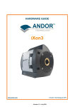
5.13 Busy Controller Module
The busy_controller module is responsible for generating the BUSY signal. It does this by evaluating inputs from
other modules and counting occupied Multi Event Buffers (MEB) in the FEE.
There are four conditions that sets the busy signal high and only one have to be true:
Figure 5-32: BUSY generation.
1. The TTCrx ready (ttcrx_rdy) is added to the BusyBox since each sub-detector should report busy if this is
not asserted. If there is a physical problem with the connection to the LTU or the CTP is issuing a global
reset, the busy is set [JohanA]. Every time a L0 trigger is detected a countdown timer (timeout_active)
starts and the busy is set for this time period. The busy time can be set manually with a register in the
Control and Status Register module.
2. The busy_controller keeps track of how many Multi Event Buffers (MEB) are occupied in the FEE. If the
number of occupied MEBs is greater or equal than then a programmable limit then BUSY is asserted.
3. The BUSY is asserted whenever the trigger receiver is busy, which means we are in the middle of a
trigger sequence.
4. The Busy Controller module increment a register (buffer_count) when a L0 is detected (L1 for TPC),
decrements the register when a L2 Reject trigger is asserted and when the Event ID Verification module
asserts the event valid signal.
The number of occupied MEBs is calculated by monitoring the triggers and the validation of event IDs process.
L1 Trigger
L2 Reject
L2 Timout
UP
DOWN
DOWN
CNT
MEB used
Event Valid
Event Payload
Figure 5-33: MEB counter.
The counter is incremented when a L1 trigger is seen. It decrements on a L2 Reject or L2 Timeout and when
event valid and event payload is active at the same time. See Figure 5-33.
5.13.1 Entity Busy Controller Module
36 | P a g e
BusyBox User Guide
Figure 5-34: Entity for Busy Controller Module.
Port Name
rst40
clk40
ttcrx_rdy
Direction
Input
Input
Input
# Bit
1
1
1
L0_trigger
L1a_trigger
Input
Input
1
1
L2a_trigger
L2r_trigger
Input
Input
1
1
L2_timeout
Input
1
busy_triggermodule
Input
1
event_valid
trig_timeout
Input
Input
1
16
fee_buffers_available
Input
4
busy_out
Output
1
fee_buffers_used
busy_time
Output
Output
4
32
Table 5-29: I/O details for Busy Controller Module.
5.14 Control and Status Registers
Description
std_logic; synchronous resets
std_logic; the clk40 frequency is 40.08 MHz.
std_logic; ttcrx_rdy out from dcs_ctrl7 (physical line on the
DCS-RCU connector). If not asserted it implies a physical
problem with connection to the LTU, or that the CTP is
issuing a global reset via the TTCrx.
std_logic; N/A
std_logic; L1a_trigger output from
trigger_receiver_busy_model. Starts buffering data in Fee if
L1a_trigger signal is asserted.
std_logic; N/A
std_logic; L1r_trigger output from
trigger_receiver_busy_model. Overwrites buffers in Fee if
L2r_trigger signal is asserted.
std_logic; L2_timeout output from
trigger_receiver_busy_model. Overwrites buffers in Fee if
L2_timeout signal is asserted.
std_logic; busy_triggermodule output from
trigger_receiver_module.
std_logic;
std_logic_vector(15 downto 0); programmable timeout
following the start of a trigger sequence. 10 us resolution.
Register 0x2008 in Control and Status Register. Set Register
to A (10 decimal) to get 100 us timeout.
std_logic_vector(3 downto 0); Holds the numbers of
buffers assumed on the FEE. Register 0x2009. Default is 4.
std_logic; busy_out is asserted when busy conditions are
met.
std_logic_vector(3 downto 0);
std_logic_vector(31 downto 0); busy_time count numbers
of clock cycles busy signal is asserted.
P a g e | 37
This module has information about register and control signals available for the BusyBox. See chapter 8 for
more information.
5.14.1 Entity Control and Status Register
Figure 5-35: Entity for Control and Status Registers.
Port Name
clk40
rst40
module_en
module_rnw
module_address
module_data_in
mem_pointer
event_count
current_eventid
most_recent_eventid
requestID
retry_count
EIDOK_vector
busy_time
module_data_out
rx_mem_matching_mask
rx_mem_pattern
fee_buffers_available
trig_timeout
req_timout
halt_validator
force_validate
CHEN_vector_out
Direction
Input
Input
Input
Input
Input
Input
Input
Input
Input
Input
Input
Input
Input
Input
Output
Output
Output
Output
Output
Output
Output
Output
Output
# Bit
1
1
1
1
12
16
10
4
36
36
4
16
120
32
16
8
8
4
16
16
1
1
120
Table 5-30: I/O details for Control and Status Registers.
Description
std_logic; the clk40 frequency is 40.08 MHz
std_logic; synchronous resets
std_logic;
std_logic;
std_logic_vector(11 downto 0);
std_logic_vector(15 downto 0);
std_logic_vector(9 downto 0);
std_logic_vector(3 downto 0);
std_logic_vector(35 downto 0);
std_logic_vector(35 downto 0);
std_logic_vector(3 downto 0);
std_logic_vector(15 downto 0);
std_logic_vector(0 to num_of_channels);
std_logic_vector(31 downto 0);
std_logic_vector(15 downto 0);
std_logic_vector(7 downto 0);
std_logic_vector(7 downto 0);
std_logic_vector(3 downto 0);
std_logic_vector(15 downto 0);
std_logic_vector(15 downto 0);
std_logic;
std_logic;
std_logic_vector(0 to num_of_channels);
38 | P a g e
6
BusyBox User Guide
Functional verification of the BusyBox firmware
6.1
Introduction
This chapter describes a testbench for the BusyBox firmware. The testbench is designed to emulate a complete
environment around the BusyBox top level module busylogic_top. The FPGA specific wrappers are not included
in the test setup.
The BusyBox interacts with the outside world through numerous interfaces:
1.
2.
3.
4.
Clocks & Reset
Trigger System; L1Trig and SerialB
DCS bus
Serial RX and TX to DRORCs
DCS bus
The testbench is impelemented in the VHDL file tb_trigger_busybox.vhd. It emulates the outside world of all
these interfaces, providing stimuli and interaction. Figure 6-1 shows a structural overview of the testbench. The
Unit Under Test (UUT) is the rectangular box in the middle. Other rectangular boxes are modules instantiated in
the testbench. Elliptic shapes are processes defined in the testbench.
serial comms
Figure 6-1: Stuctural overview of the testbench for the BusyBox logic.
The clock generators are simply concurrent procedure calls to clk_gen in the busybox_tb_pkg. See section 6.2.1
for more details on the procedure. The system needs two clocks to operate, one at 200 MHz and one at 40 MHz.
p_clockA : clkgen(clkA_period, clk_en, clk200);
p_clockB : clkgen(clkB_period, clk_en, clk40);
P a g e | 39
The process tb_main generates trigger sequences and access registers in the UUT over the DCS bus. An extra
trigger_receiver is instantiated in the testbench to acquire the same trigger information as produced by the
trigger_receiver in the UUT. The decoded triggers are read out from the extra trigger_receiver and the eventID
is extracted and pushed to the rcu_drorc_emulator modules which communicate with the BusyBox over serial
links.
The trigger sequences are easily generated by a procedure call to run_sequence defined in the busybox_tb_pkg
VHDL package which is described in section The busybox_tb_pkg package6.2.1.
6.2
Support packages
The testbench makes use of the following packages:
•
•
•
•
•
•
6.2.1
ieee.std_logic_1164.all; IEEE package defining std_logic type and derived types.
ieee.numeric_std.all; - IEEE package for numeric operations on std_logic based (sub)types
ieee.math_real.all; - IEEE package for math operations, used for random generation.
std.textio.all; - Package for modifying and printing text strings.
work.tb_pkg.all;
work.busybox_tb_pkg.all; - Package containing various definitions of types, functions and procedures
used in the testbench.
The busybox_tb_pkg package
This package was written specifically for this testbench and holds definitions required by it.
A record type is defined that contains all signals related to the bus interface with the DCS board. Procedures for
performing read and write operations on this interface are also defined.
type t_bb_bus_record is record
strobe_n
: std_logic;
RnW
: std_logic;
addr
: std_logic_vector(15 downto 0);
data
: std_logic_vector(15 downto 0);
ack_n
: std_logic;
end record t_bb_bus_record;
Procedures for performing master read and write bus transactions using the bus record types defined in the
package. The procedures are used for accessing and testing the internal busybox registers during simulation.
They must be called from a sequential process and will block the calling process until they return.
procedure bb_bus_read
constant addr
:
variable data
:
signal bb_bus
:
(
in
std_logic_vector;
out
std_logic_vector;
inout t_bb_bus_record);
procedure bb_bus_write (
constant addr, data : in
std_logic_vector;
signal bb_bus
: inout t_bb_bus_record);
The clk_gen procedure makes it easy to generated clocks in the testbench. The procedure is called from the
concurrent section of a module and will act as a process.
40 | P a g e
BusyBox User Guide
•
The period is specified by a constant and cannot be changed afterwards.
•
The clock output can be enabled or disabled by the clk_en input.
procedure clkgen(
constant period
signal clk_en
signal clk
: in time;
: in boolean;
: out std_logic);
For a convenient and compact definition of a trigger sequence a record type is defined that holds all relevant
parameters of a trigger sequence. A defined sequence is executed by calling a procedure (run_sequence) with
an instance of this record type is one of its parameters.
type sequence_type is record
description
: string(1 to 80);
L0_enable
: boolean;
L1_enable
: boolean;
L1Msg_enable
: boolean;
L2Msg_enable
: boolean;
L2Accept
: boolean;
L1_latency
: time;
L1Msg_latency
: time;
L2Msg_latency
: time;
L1_ESR
: std_logic;
L1_CIT
: std_logic;
L1_SwC
: std_logic;
L1_RoC
: std_logic_vector(3 downto 0);
L1_Class
: std_logic_vector(49 downto 0);
L2_ESR
: std_logic;
L2_CIT
: std_logic;
L2_SwC
: std_logic;
L2_Cluster
: std_logic_vector(5 downto 0);
L2_Class
: std_logic_vector(49 downto 0);
BCID
: std_logic_vector(11 downto 0);
OrbitID
: std_logic_vector(23 downto 0);
end record sequence_type;
A more detailed description of the trigger sequence parameters follow:
Parameter
description
L0_enable
L1_enable
L1Msg_enable
L2Msg_enable
L2Accept
L1_latency
L1Msg_latency
L2Msg_latency
Description
A string of 80 characters that can be used to describe the sequence.
This string will be printed to console when the sequence is executed
during simulation runs.
Include the L0 trigger in the sequence
Include the L1 trigger in the sequence
Include the L1 Message in the sequence
Include the L2 Message in the sequence
true => Level 2 Accept Message
false => Level 2 Reject Message
Latency from rising edge of L0 trigger to rising edge of L1 trigger on
the L1Trig signal
Latency from rising edge of L0 trigger to the start bit of the L1
Message on the serialB signal
Latency from rising edge of L0 trigger to the start bit of the L2
Default value
"Default sequence
L0-L1A-L1MsgL2AMsg.”
true
true
true
true
true
5.3 µs
6.3 µs
85 µs
P a g e | 41
L1_ESR
L1_CIT
L1_SwC
L1_RoC
L1_Class
L2_ESR
L2_CIT
L2_SwC
L2_Cluster
L2_Class
BCID
OrbitID
Message
Level 1 Message content : Enable Segemented Readout
Level 1 Message content: Calibration trigger flag
Level 1 Message content: Software trigger
Level 1 Message content: ReadOut Chamber
Level 1 Message content: Level 1 Class trigger state flag
Level 2 Message content: Enable Segmented Readout
Level 2 Message content: Calibration trigger flag
Level 2 Message content: Software trigger flag
Level 2 Message content: Cluster trigger flag
Level 2 Message content: Level 2 Class trigger flag
Level 2 Message content: Bunch Crossing ID
Level 2 Message content: Orbit ID
‘0’
‘0’
‘0’
“0000”
(others => ‘0’)
‘0’
‘0’
‘0’
(others => ‘0’)
(others => ‘0’)
X”789”
X”123456”
•
•
•
•
It is a required relationship that L1_latency < L1Msg_latency < L2Msg_latency.
The BCID and OrbitID values combined make up the eventID.
Message content entries besides the eventID are not relevant for the BusyBox operation.
A constant with default values for all parameters is defined in the busybox_tb_pkg. This constant can
be used as init value to instantiate a record with default values.
Refer to documentation for the ALICE trigger system for more information on the message contents.
Procedure for executing a sequence and driving the L1Trig and SerialB signals.
procedure run_sequence (
signal clk
: in std_logic;
constant seq
: in sequence_type;
signal L1trig : out std_logic;
signal serialb : out std_logic);
The procedure produces a sequence in the following order L0 tirgger – L1 trigger – L1 Message – L2 Message.
The different stages can be enabled and disabled by setting the flags in the sequence record type. The L0 trigger
is executed at the first rising edge of the testbench clock after the procedure is called. All other latencies are
referenced from this time. If e.g. the L2 Message latency has already passed when the L1 message is finished, it
will be executed right away. This is true for all latencies defined in the trigger sequence record type.
6.3
The RCU and DRORC emulator module
This module has been designed to emulate the RCU and DRORC devices from the BusyBox’s point of view. Only
the functions required for the operation of the BusyBox are emulated. In the real system the RCUs will read
event data from the Front End Cards and push it to the DRORCs. The event data is preceded by a Common Data
Header (CDH) which contains information related to the event, amongst others the EventID. When the DRORC
has received an event, including the CDH, from the RCU the EventID is extracted and put in a FIFO queue. When
the BusyBox requests a new EventID, the DRORC will look for it in this FIFO queue. Since the size of the event
data will vary between events and FEE patches (RCU with FECs attached) the time taken from an event has been
triggered until the EventID ends up in the DRORCs EventID queue will vary as well.
To emulate this behaviour the rcu_drorc_emulator module has to FIFOs for eventIDs. The first is used for storing
EventIDs as they are triggered and the second to hold EventIDs that have been transmitted to the DRORCs.
Internally the module generates random times from 100 to 500 µs that it will wait before moving an EventID
42 | P a g e
BusyBox User Guide
from the first FIFO to the second. The random time emulates the variance in event data sizes. The concept is
illustrated in Figure 6-2.
Figure 6-2: Illustration of the RCU and DRORC emulation.
The number of EventIDs stored in the FEE buffer corresponds to Multi Event Buffers (MEBs) in use on the real
system. This number is monitored by the testbench to check that it never exceeds the specified maximum
numbers events that can be stored on the FEE. The DRORC emulator takes care of the communications with the
BusyBox. Requests/commands from the BusyBox are handled in the same manner as for the real DRORC. Serial
receiver and transmitter modules are used for communication with the BusyBox.
6.4
Testbench execution flow
The process tb_main controls the simulation. It begins by setting some signals to default values and resetting
the UUT and any support modules. At line 7 the dcm_lock signal is asserted to indicate to the busylogic_top
module the the DCM has locked on the external clock. Then the reset is released. At lines 11 and 12 it writes to
two configuration registers to set the MEB limit to 4 and release the busybox FSM (set the halt FSM bit to 0). All
other registers are left at their default value. Now the BusyBox should release the BUSY and be ready to receive
triggers.
1
2
3
4
5
6
7
8
9
10
11
12
13
14
15
16
17
18
19
20
21
22
23
24
25
clk_en <= true;
dcm_lock <= '0';
serialb <= '1';
L1trig <= '0';
areset <= '1';
wait for 200 ns;
dcm_lock <= '1';
wait for 10 us;
areset <= '0';
header("Testbench for BusyBox", "A sequence of basic triggers.");
bb_bus_write(X"2009", X"0004", dcs_bus); -- set MEB to 4
bb_bus_write(X"200A", X"0000", dcs_bus); -- release busybox FSM
wait for 500 ns;
run_sequence(clk40, trigger_sequence1, L1trig, serialB);
wait for 100 us;
run_sequence(clk40, trigger_sequence1, L1trig, serialB);
wait until busy_out = '0';
run_sequence(clk40, trigger_sequence1, L1trig, serialB);
wait until busy_out = '0';
run_sequence(clk40, trigger_sequence1, L1trig, serialB);
wait until busy_out = '0';
run_sequence(clk40, trigger_sequence1, L1trig, serialB);
wait until busy_out = '0';
run_sequence(clk40, trigger_sequence1, L1trig, serialB);
wait until busy_out = '0';
P a g e | 43
26
27
28
29
30
31
32
33
34
35
36
37
38
39
run_sequence(clk40,
wait until busy_out
run_sequence(clk40,
wait until busy_out
run_sequence(clk40,
wait until busy_out
run_sequence(clk40,
wait until busy_out
run_sequence(clk40,
wait until busy_out
run_sequence(clk40,
wait until busy_out
clk_en <= false;
wait;
trigger_sequence1, L1trig, serialB);
= '0';
trigger_sequence1, L1trig, serialB);
= '0';
trigger_sequence1, L1trig, serialB);
= '0';
trigger_sequence1, L1trig, serialB);
= '0';
trigger_sequence1, L1trig, serialB);
= '0';
trigger_sequence1, L1trig, serialB);
= '0' and BusyBox_MEB_cnt = "0000";
Next, the process starts sending trigger sequences by calling the run_sequence procedure. A wait statement
ensures that BUSY is not asserted before sending a trigger sequence. The simulation will end when all
statements in this process have completed. The final statements wait until the BUSY has been de-asserted and
the BusyBox MEB count has reached 0. Then the clocks are disabled and the process goes to sleep.
During the entire simulation a concurrent assert statement makes sure that the MEB counts from all the
rcu_drorc_emulator modules are never higher than the MEB count of the BusyBox. This is important as it tests
whether the BusyBox will toggle the BUSY output correctly so that the FEE cannot experience buffer overflows
during operation.
assert RCU_MEB_cnt_array(i) <= BusyBox_MEB_cnt
report "Possible Buffer overflow detected!"
severity warning;
Below is an excerpt from the output/console when running the testbench.
#
#
#
#
#
#
#
#
#
#
#
#
#
#
#
#
#
#
#
#
#
#
#
#
#
#
#
#
10400 ns: bb_bus_write: ADDR 0x2009 DATA 0x0004
10650 ns: bb_bus_write: ADDR 0x200A DATA 0x0000
11200 ns: Running trigger sequence number 1
11200 ns: Sending Level 0 Trigger.
16500 ns: Sending Level 1 Trigger. Time since sequence init : 5300 ns
17500 ns: Sending Level 1 Message. Time since sequence init : 6300 ns
96200 ns: Sending Level 2 Accept Message. Time since sequence init : 85000 ns
==================== Trigger Receiver DAQ event FIFO ====================
Event Info : 0xA9501800
+ Bit 11 : L2 Accept received.
+ Bit 12 : Include payload.
Event Error : 0x00002000
+ Bit 13 : Buondary L1.
DAQ1
: 0x02000789
DAQ2
: 0x00123456
DAQ3
: 0x00000000
DAQ4
: 0x0100028E
DAQ5
: 0x00000000
DAQ6
: 0x00000000
DAQ7
: 0x00000000
=========================================================================
204850 ns: Running trigger sequence number 2
204850 ns: Sending Level 0 Trigger.
210150 ns: Sending Level 1 Trigger. Time since sequence init : 5300 ns
211150 ns: Sending Level 1 Message. Time since sequence init : 6300 ns
289850 ns: Sending Level 2 Accept Message. Time since sequence init : 85000 ns
==================== Trigger Receiver DAQ event FIFO ====================
Event Info : 0xA9501800
44 | P a g e
#
#
#
#
#
#
#
#
#
#
#
#
BusyBox User Guide
+ Bit 11 : L2 Accept received.
+ Bit 12 : Include payload.
Event Error : 0x00002000
+ Bit 13 : Buondary L1.
DAQ1
: 0x02000789
DAQ2
: 0x00123456
DAQ3
: 0x00000000
DAQ4
: 0x010000D0
DAQ5
: 0x00000000
DAQ6
: 0x00000000
DAQ7
: 0x00000000
=========================================================================
6.5
Running the simulation in QuestaSim/ModelSim
1)
2)
3)
4)
5)
6)
start questa/modelsim
cd to trunk/simulation
source project_setup.tcl
vsim tb_trigger_busybox
add wave *
run –all
Some files (only testbench files) may fail compilation because they use some features from VHDL 2008. Set the
compiler to use VHDL 2008 to compile these files.
P a g e | 45
7
BusyBox DCS board
Figure 7-1: PCB layout of DCS board.
#
1
2
3
4
Type
Optical input
UART
Connector
Ethernet
Description
Input from LTU or CTP emulator
RS-422 connection
DCS bus connector to BusyBox PCB
Ethernet link to communicate with DCS board
Table 7-1: Connectors on the DCS board.
46 | P a g e
7.1
BusyBox User Guide
Setting up DCS board Firmware to use with BusyBox
The DCS board firmware needs to be adapted for the BusyBox. If the DCS board is not already modified, it needs
to be reprogrammed to fit the BusyBox. The latest firmware is available here:
https://wikihost.uib.no/ift/index.php/Electronics_for_the_Time_Projection_Chamber_%28TPC%29#DCS_board_
firmware_for_TPC_and_PHOS
Here a description of how to update the DCS board flash device is also given.
P a g e | 47
8
BusyBox Communication
This chapter discusses the how the BusyBox handles communication with the D-RORCs.
8.1
BusyBox - DRORC Communication
A robust serial communication has been developed for communication between the BusyBox and the D-RORCs.
Serial, 48 bit oriented, bidirectional data transfer can be made at up to
-
8.1.1
Physical Layer
Category 5 cables with RJ-45 connectors are the communication channel between the BusyBox and D-RORCs.
Built in I/O blocks in the Virtex-4 FPGA is set to I/O standard specified as LVDS_25 and DIFF_TERM attribute is
set to true.
Figure: 8-1: RJ-45 pin connection scheme.
8.1.2
Data Link Layer
Serial data is transmitted with NRZ encoding at a 40 MHz bit rate. Three 16 bit data packages are sent from the
D-RORCs to the BusyBox on request from the BusyBox. The packages are concatenated to one 48 bit message in
the BusyBox receiver module. The messages from the BusyBox to the D-RORCs are 16 bit long.
The receiver samples the incoming serial data at 200 MHz into a 98 bit shift register. When bits 1 to 8 are
‘00001111’ and bits 96 to 98 are ‘000’ in the shift register, the capture condition is valid, and the data is passed
to the majority vote.
Bit range
1 2 3 4 5 6 7 8 .
.
.
96
97
98
Bit value
0 0 0 0 1 1 1 1 x x x
0
0
0
Table 8-1: Capture condition for a data frame.
One bit period is 5 cycles and the three middle bits are run through a majority gate. The captured data word is
17 bit long with the LSB as the parity bit. If there is any parity error or timeout error during the data capture
data is discarded. The timeout clock counts 110 cycles from the first received bit before a timeout error is issued.
When three 16 bit data packages are received without error they are concatenated into a 48 bit package and
stored.
48 | P a g e
Bit
position
P1
P2
P3
P4
BusyBox User Guide
8
P4
P4
7
D4
X
X
X
X
6
D3
X
X
X
5
D2
X
X
X
4
P3
P3
X
3
D1
X
X
2
P2
X
X
1
P1
P1
P2
X
Table 8-2: Hamming code table.
Messages from the BusyBox to the D-RORCs are Hamming encoded with an 8:4 code applied and sent in series.
Each bit is cycled five times and the transmission starts with two start bits followed by 16 data bit, one parity bit
and a stop bit.
Figure 8-1: One serial data transmission.
8.1.3
Network Layer
The BusyBox will request event IDs from all active D-RORCs when a Level 2 Accept trigger is issued. The
transmitter will keep sending new request at a programmable time interval until all the D-RORC have replied.
Request can either be issued automatically by the firmware or manually by the DCS software.
15 -12
Command type
11 – 8
Request ID
7–0
Unused
Table 8-3: Bit-map for BusyBox Messages.
The messages from the D-RORCs are 48 bits long and the time to receive one message is 1.2 µs. Every channel is
checked every 120 clock cycle, i.e. 3 µs.
47 – 44
Request ID
43 – 32
Bunch Count ID
Table 8-4: Bit-map for D-RORC messages.
31 – 8
Orbit ID
7 -0
D-RORC ID
P a g e | 49
8.1.4
Sequence Diagrams
Start
Reset ststus registers
No
EventID in Queue?
Yes
Pop EventID from Queue
Generate Request ID
Request EventID from D-RORCs
Start timer
Start: Reveived messages from BusyBox
Process incomming messages
New request ID?
Update status registers
No
Yes
Yes
Event Valid?
No
New eventID available?
No
Timeout?
Yes
Yes
Store received request ID
Update masking vector
Increment retry counter
Retry >= limit?
Pop eventID from queue
No
Update output buffer
Yes
Update error registers
Transmit output buffer to BusyBox
Wait for DCS intervention
Figure 8-2: Sequence diagram for the BusyBox (on the left) and D-RORC (on the right)
See chapter 4.5 and 4.6 for more information on how the sending and receiving hardware modules work.
50 | P a g e
8.2
BusyBox User Guide
TTCrx Communication
The trigger information from the LTU is acquired by the TTC receiver chip (TTCrx) on the DCS board. The Trigger
Receiver module on the BusyBox decodes the information into three parts: Channel A, Channel B and BC.
Channel A
L0 and L1 triggers are transmitted on Channel A using LVDS from the TTCrx chip
Channel B
Channel B transmits two types of messages: Broadcast messages and individual address messages. The
broadcast message is decoded into a pre-pulse bit, an event count reset bit and a bounchcount reset bit. The
individual addressed messages are decoded into L1a, L2a, L2r and RoI messages.
BC
The Bunch Count, 40 MHz, is distributed to the BusyBox logic and DCS board.
8.3
DCS Communication
Figure 8-3: Read and write transactions on the DCS bus. From [Magne]
Communication between the DCS board FPGA and the BusyBox motherboard FPGA is a 16 bit asynchronous
handshake protocol. The DCS card is the master and the FPGA is the slave. A transaction starts with STROBE_N
on the DCS and ACK_N from the BusyBox. RnW indicates read/write and when reading the BusyBox drives the
data lines. When writing, the DCS board drives the data lines. If an address given by the DCS board does not
point to any module/sub-module in the BusyBox firmware the request is be ignored, and the transaction times
out.
FPGA address
15
Module address
14 – 12
Sub module address
11 – 0
Table 8-5: Bit-mapping of DCS bus address.
8.4
LTU Communication
The BusyBox has two LEMO contacts. The busy signal is driven through a CERN certified LVDS driver via coaxial
cables from the counting room to the LTU in the experiment hall.
P a g e | 51
9
Getting started with the BusyBox
This chapter will give some insight in how to get started with the BusyBox and make changes to the firmware.
In addition the CTP emulator will be discussed.
9.1
Introduction
TCL scripts sets up projects in Xilinx ISE Design Suit and Mentor Graphics’ QuestaSim. All the files needed for the
BusyBox are in a repository. The scripts are written to implement the files to checkout and build or simulate the
design.
Furthermore, knowledge about the interaction with the BusyBox hardware is given on how to program,
read/write registers and test the design with triggers from a trigger emulator.
9.2
SVN Repository and Project Setup
The BusyBox firmware has been written in Xilinx ISE Design Suite and tested in Mentor Graphics’ QuestaSim.
The source code and other relevant files for the BusyBox are stored in a SVN repository to make it easy to see
the latest work done.
9.2.1
SVN Repository
A repository has been created to have a place where
data is stored and maintain for future retrieval to
manage ongoing development of digital documents in
the BusyBox project. Any changes in the document
are identified by incrementing an associated number,
termed the revision number. The University of Bergen
uses a SVN repository.
TortoiseSVN is an open source revision control
software for Microsoft Windows. To download the
software, go to:
http://tortoisesvn.net/downloads
TortoiseSVN is a shell extension that is integrated into
the Windows explorer. So, after you have downloaded
and installed TortoiseSVN, open the explorer and
right-click on any folder you like to bring up the
context menu where you will find all TortoiseSVN
commands.
Figure 9-1: TortoiseSVN example.
Select “TortoiseSVN” and “Create repository here”.
Then you right-click on the folder again and select “Import”. The URL for the repository is:
https://svn.ift.uib.no/svn/busybox_firmware
Username and password can be acquired by contacting the microelectronics division at IFT, UIB.
52 | P a g e
9.3
BusyBox User Guide
Hardware Setup
Figure 9-2: Principle hardware setup for experimenting with the BusyBox
The BusyBox is connected to the Ethernet and the CTP Emulator. The physical distance between the two devices
are limited by the optical cable, and the PC can be anywhere, but for practical reasons it should be in near
proximity to the others.
The optical fibre cable from the CTP Emulator goes into #1 in figure 5-1.
The Ethernet cable goes into #4 in figure 5-1.
The Ethernet connector on the DCS card is a 6 pin Milli-Grid crimp housing and the cable connections can be
found here:
http://www.kip.uni-heidelberg.de/ti/DCS-Board/current/mechanic/DCS160Ethernet01.htm
9.4
Logging on to the DCS board
The DCS board mounted on the BusyBox is the easiest way to interact with the firmware. From her registers can
be accessed and new firmware can be programmed to the Virtex-4 chip(s).
Interfacing with the DCS board is done either trough Ethernet or UART, but Ethernet is the preferred way. The
DCS board runs on a lightweight version of Linux and is access through a SSH shell. For Microsoft Windows users
a SSH client can be used like the PuTTY SSH client.
Open a terminal window on a Linux computer or a SSH client on a Windows computer.
To login type:
ssh root@dcsxxxx
The xxxx is substituted with the number on the DCS card. Then you will be prompted for a password.
To get the password contact:
P a g e | 53
9.5
RCU Shell
The RCU Shell is a small command-line software for communicating with the firmware on the BusyBox. It is
started by simply typing 'rcu-sh' at the command-line. This will bring you to the shell mode, where different
types of commands can be executed, for example for reading and writing registers in the BusyBox firmware.
Type “h” and press “enter” to see available commands in the RCU shell.
9.6
Programming the FPGA
The FPGA(s) will not be programmed automatically when the box is powered up. To check if the FPGAs are
programmed one can try to read some register with the RCU shell, e.g: shell prompt on DCS board: rcu-sh r
0x1000.
If the result is “no target answer” then the FPGA is not programmed. Otherwise you should get the value of the
register.
The easist way to program the FPGAs is to use the shell script "program". This script should be located with the
programming files for the FPGAS (*.bit) in the directory "/mnt/dcsbro/busy/busybox-files/"
Prompt on DCS board: ./program <programmingfile1.bit> [<programmingfile2.bit>]
There should be four programming files in the directory:
1. busybox_fpga1.bit for the first of two FPGAs
2. busybox_fpga2.bit for the second of two FPGAs
3. busybox_fpga1_solo.bit for FPGAs on boards/boxes where only on FPGA is mounted.
4. busybox_dummy.bit will be used by the script to program the second FPGA if no second programming file is
given.
Note: When two FPGAs are mounted then both must be programmed, or the firmware will not start up.
The bit files to be programmed into the FPGA(s) must be put in the folder:
/nfs_export/dcscard on kjekspc7.
9.7
Configuring the Firmware
Modify the shell script bbinit.sh to fit your setup.
9.8
Monitoring the BusyBox registers
Use regpoll.sh status to view most of the status registers of the BusyBox.
Type:
./regpoll.sh status
To display the channel registers use regpoll.sh channels.
Type:
54 | P a g e
BusyBox User Guide
./regpoll.sh channels
9.9
Resetting the BusyBox
To activate the global asynchronous reset of the Busy Box firmware (both FPGAs)run "rcu-sh fw r". This will
reset all registers in the Busy Box (except for the block RAMs).The configuration registers must be set again,
including channel registers. Sending and Receiving messages to/from the D-RORCs.
9.10 CTP Emulator
When testing or debugging the BusyBox a trigger emulator can be used.
Open a terminal window in Linux.
Type: ssh –X ltu@vme1, and enter the password when prompted.
Type: vmecrate ltu.
Figure 9-3: Example of login.
Then the VME menu is displayed.
Click Configuration and LTUinit.
Click Configuration and TTCreset.
Click CTP Emulator.
The CTP Emulator window pops up.
P a g e | 55
Next to the Sequence tag click L2a.seq and click Load sequence.
Click Start emulation.
So, when you click the Generate SW ‘Start signal(s)’ trigger sequences are sent to the BusyBox.
To get the password contact:
56 | P a g e
BusyBox User Guide
10 Register
All registers for the BusyBox are listed below.
10.1 BusyBox Register Interface
Register Name
TX Register[15:0]
Address
0x30001
Type
RW
RX Memory1[15:0]
RW
RX Memory Pointer[11:0]
0x10000x1FFF
0x10000x1FFF
0x10000x1FFF
0x10000x1FFF
0x2000
Event ID Count[8:0]
0x2001
R
Current EventID[3:0]
Current EventID[15:0]
Current EventID[15:0]
Newest EventID[3:0]
0x2002
0x2003
0x2004
0x2005
R
R
R
R
Newest EventID[15:0]
0x2006
R
Newest EventID[15:0]
0x2007
R
L0 trigger timeout
0x2008
RW
0x2009
RW
Halt FSM[0]
0x200A
RW
Force Event ID Match[0]
0x200B
W
Re-request Timeout[15:0]
0x200C
RW
Current Request ID[3:0]
0x200D
R
Request
Count[15:0]
Busy Timer[15:0]
0x200E
R
0x2010
R
RX Memory2[15:0]
RX Memory3[15:0]
RX Memory4[15:8]
FEE
Available[3:0]
6
Buffers
Retry
6
RW
RW
RW
R
Legend: W=write, R=read, T= write trigger (not physical registers)
Decription
Transmits a message on serial ports when
written to. Bit 7:0 is TX Data. Bit 15:8 gives
channel number in hexadecimal. Any value
greater than the actual number of channels will
result in a broadcast on all channels.
All addresses in range where the 2 LSBs are
‘00’. Holds DRORC message [47:32].
All addresses in range where the 2 LSBs are
‘01’. Holds DRORC message [31:16].
All addresses in range where the 2 LSBs are
‘10’. Holds DRORC message [15:0].
All addresses in range where the 2 LSBs are
‘11’. Holds DRORC channel number.
Value indicates where next message from
DRORC will be written in RX Memory.
Number of Event Ids extracted from triggers and
stored in FIFO.
Bit 35:32 of Event ID currently being matched.
Bit 31:16 of Event ID currently being matched.
Bit 15:0 of Event ID currently being matched.
Bit 35:32 of Event ID most recently received
from triggers.
Bit 31:16 of Event ID most recently received
from triggers.
Bit 15:0 of Event ID most recently received from
triggers.
Number of clock cycles 'busy' will be asserted
after an L0 trigger. Note: The busy will not be
deasserted if the buffers are full.
Configuration register which indicates how
many events can be stored in the buffers on the
FEE.
When set to ‘1’ the FSM that controls the Event
ID matching will halt in a known state.
Writing ‘1’ to this register when the FSM has
been halted will cause the FSM to move on to
the next Event ID.
Number of clock cycles (40 MHz domain) to
wait in between sending requests to the
DRORCs.
Holds the Request ID the Busy Box uses to
request Event Ids from the DRORCs.
Number of iterations the FSM has made while
trying to match the current Event ID.
Bit 31:16 of register that holds number of cycles
the BUSY has been asserted.
P a g e | 57
Busy Timer[15:0]
0x2011
R
RX Memory
Filter[15:0]
0x2012
RW
L0 deadtime offset[15:0]
0x2013
RW
L0 deadtime offset[15:0]
0x2014
RW
Channel Register[3:0]
0x21XX
RW
Bit 15:0 of register that holds number of cycles
the BUSY has been asserted.
Filters which messages will be stored in RX
Memory by channel number. Bit 7:0 is matching
pattern. Bit 15:8 is matching mask to
enable/disable matching of individual bits.
Bit 31:16 of register that holds number of cycles
the ‘busy’ will be asserted after a L0 trigger.
Bit 15:0 of register that holds number of cycles
the ‘busy’ will be asserted after a L0 trigger.
Provides information on status of channel ‘XX’.
Bit 0: ‘1’ receiver for the channel is enabled and
a matching Event ID from this channel is
required. Bit 1: ‘1’ indicates that the current
Event ID has been matched for this channel.
This bit is read only.
Table 10-1:List of registers that can be accessed externally.
10.2 Trigger Receiver Module Register Interface
Register name
Control[15:0]
Address
0x3000
Type
RW
Control[7:0]
0x3001
R
Module reset
RoI_Config1[15:0]
RoI_Config1[1:0]
RoI_Config2[15:0]
RoI_Config2[1:0]
Reset_Counters
0x3002
0x3004
0x3005
0x3006
0x3007
0x3008
T
RW
RW
RW
RW
T
Issue_TestMode
0x300A
T
L1_Latency[15:0]
0x300C
RW
L2_Latency[15:0]
L2_Latency[15:0]
PrePulse_Latency[7:0]
0x300E
0x300F
0x3010
RW
RW
RW
7
7
Legend: W=write, R=read, T= write trigger (not physical registers)
Description
[0] Serial B channel on/off
Default: 1
[1] Disable_error_masking
0
[2] Enable RoI decoding
0
[3] L0 support
1
[4:7] (Not Used)
[8] L2a FIFO storage mask
1
[9] L2r FIFO storage mask
1
[10] L2 Timeout FIFO storage mask
1
[11] L1a message mask
1
[12] Trigger Input Mask Enable
0
[13:15] (Not Used)
[16] Bunch_counter overflow
[17] Run Active
[18] Busy (receiving sequence)
[19] Not Used
[23:20] CDH version
0x2
Reset Module
RoI-Definition. Bit 15:0
RoI Definition. Bit 17:16
RoI Definition. Bit 33:18
RoI Definition. Bit 35:34
Write to this registers will reset the counters in
the module
Debug: Issues testmode sequence. Note that
serialB channel input MUST be disabled when
using this feature.
[15:12] Uncertainty region +- N. default value
0x2 (50 ns)
[11:0] Latency from L0 to L1, default value
0x30D4 (5.3 us)
[15:0] Max Latency from BC0 to L2
[31:16] Min Latency from BC0 to L2
58 | P a g e
BusyBox User Guide
RoI_Latency[15:0]
RoI_Latency[15:0]
L1_msg_latency[15:0]
L1_msg_latency[15:0]
Pre_pulse_counter[15:0]
BCID_Local[11:0]
0x3012
0x3013
0x3014
0x3015
0x3016
0x3018
RW
RW
RW
RW
RW
R
L0_counter[15:0]
L1_counter[15:0]
L1_msg_counter[15:0]
L2a_counter[15:0]
L2r_counter[15:0]
RoI_counter[15:0]
Bunchcounter[11:0]
hammingErrorCnt[15:0]
hammingErrorCnt[15:0]
ErrorCnt[15:0]
ErrorCnt[15:0]
0x301A
0x301C
0x301E
0x3020
0x3022
0x3024
0x3026
0x302C
0x302D
0x302E
0x302F
R
R
R
R
R
R
R
R
R
R
R
Buffered_events[4:0]
DAQ_Header01[15:0]
DAQ_Header01[15:0]
DAQ_Header02[15:0]
DAQ_Header02[15:0]
DAQ_Header03[15:0]
DAQ_Header03[15:0]
DAQ_Header04[15:0]
DAQ_Header04[15:0]
DAQ_Header05[15:0]
DAQ_Header05[15:0]
DAQ_Header06[15:0]
DAQ_Header06[15:0]
DAQ_Header07[15:0]
DAQ_Header07[15:0]
Event_info[11:0]
0x3040
0x3042
0x3043
0x3044
0x3045
0x3046
0x3047
0x3048
0x3049
0x304A
0x304B
0x304C
0x304D
0x304E
0x304F
0x3050
R
R
R
R
R
R
R
R
R
R
R
R
R
R
R
R
Event_error[15:0]
0x3052
R
[15:0] Max Latency from BC0 to RoI msg
[31:16] Min Latency from BC0 to RoI msg
[15:0] Max Latency from BC0 to L1 msg
[15:0] Max Latency from BC0 to L1 msg
Number of decoded pre-pulses.
Number of bunchcrossings at arrival of L1
trigger.
Number of L0 triggers
Number of L1 triggers
Number of successfully decoded L1 messages
Number of successfully decoded L2a messages
Number of successfully decoded L2r messages
Number of successfully decoded RoI messages
Debug: Number of bunchcrossings
[15:0] Number of single bit hamming errors
[31:16] Number of double bit hamming errors
[15:0] Number of message decoding errors
[31:16] Number of errors related to sequence
and timeouts.
Number of events stored in the FIFO.
Latest received DAQ Header 1 [15:0]
Latest received DAQ Header 1 [31:16]
Latest received DAQ Header 2 [15:0]
Latest received DAQ Header 2 [31:16]
Latest received DAQ Header 3 [15:0]
Latest received DAQ Header 3 [31:16]
Latest received DAQ Header 4 [15:0]
Latest received DAQ Header 4 [31:16]
Latest received DAQ Header 5 [15:0]
Latest received DAQ Header 5 [31:16]
Latest received DAQ Header 6 [15:0]
Latest received DAQ Header 6 [31:16]
Latest received DAQ Header 7 [15:0]
Latest received DAQ Header 7 [31:16]
[0] RoI enabled
[1] Region of Interest announced (=ESR)
[2] RoI received
[3] Within region of interest
[4:7] Calibration/SW trigger type (= RoC)
[8] Software trigger event
[9] Calibration trigger event
[10] Event has L2 Reject trigger
[11] Event has L2 Accept trigger
[0] Serial B Stop Bit Error
[1] Single Bit Hamming Error Individually Addr.
[2] Double Bit Hamming Error Individually Addr.
[3] Single Bit Hamming Error Broadcast.
[4] Double Bit Hamming Error Broadcast.
[5] Unknown Message Address Received
[6] Incomplete L1 Message
[7] Incomplete L2a Message
[8] Incomplete RoI Message
[9] TTCrx Address Error (not X”0003”)
[10] Spurious L0
[11] Missing L0
[12] Spurious L1
[13] Boundary L1
P a g e | 59
Event_error[11:0]
0x3053
R
L1_MessageHeader[11:0]
L1_MessageData1[11:0]
L1_MessageData2[11:0]
L1_MessageData3[11:0]
L1_MessageData4[11:0]
L2aMessageHeader[11:0]
L2aMessageData1[11:0]
L2aMessageData2[11:0]
L2aMessageData3[11:0]
L2aMessageData4[11:0]
L2aMessageData5[11:0]
L2aMessageData6[11:0]
L2aMessageData7[11:0]
L2rMessageHeader[11:0]
RoIMessageHeader[11:0]
RoIMessageData1[11:0]
RoIMessageData2[11:0]
RoIMessageData3[11:0]
FIFO_read_enable
FIFO_DAQHeader[15:0]
FIFO_DAQHeader[15:0]
0x3060
0x3062
0x3064
0x3066
0x3068
0x306A
0x306C
0x306E
0x3070
0x3072
0x3074
0x3076
0x3078
0x307A
0x307C
0x307E
0x3080
0x3082
0x3100
0x3102
0x3103
R
R
R
R
R
R
R
R
R
R
R
R
R
R
R
R
R
R
T
R
R
[14] Missing L1
[15] L1 message arrives outside legal timeslot
[16] L1 message missing/timeout
[17] L2 message arrives outside legal timeslot
[18] L2 message missing/timeout
[19] RoI message arrives outside legal timeslot
[20] RoI message missing/timeout
[21] Prepulse error (=0; possible future use)
[22] L1 message content error
[23] L2 message content error
[24] RoI message content error
Debug: Latest received L1 Message
Debug: Latest received L1 Message
Debug: Latest received L1 Message
Debug: Latest received L1 Message
Debug: Latest received L1 Message
Debug: Latest received L2a Message
Debug: Latest received L2a Message
Debug: Latest received L2a Message
Debug: Latest received L2a Message
Debug: Latest received L2a Message
Debug: Latest received L2a Message
Debug: Latest received L2a Message
Debug: Latest received L2a Message
Debug: Latest received L2r Message
Debug: Latest received RoI Message
Debug: Latest received RoI Message
Debug: Latest received RoI Message
Debug: Latest received RoI Message
Debug: Triggers a readout pulse to FIFO
Debug: Output of FIFO [15:0]
Debug: Output of FIFO [31:16]
Table 10-2: List of registers that can be accessed externally. Note that the registers marked debug can be excluded by
setting the generic include_debug_registers to false, but during the development of HW/FW they come in handy for
testing and verification. The module address is not given in this table.
10.3 TPC Channel Register Interface
Ch
0
1
2
3
4
5
6
7
8
9
10
11
12
13
14
15
Address
0X2100
0X2101
0X2102
0X2103
0X2104
0X2105
0X2106
0X2107
0X2108
0X2109
0X210a
0x210b
0x210c
0x210d
0x210e
0x210f
TPC
C00
C00
C00
C00
C00
C00
C01
C01
C01
C01
C01
C01
C02
C02
C02
C02
Patch
RCU0
RCU1
RCU2
RCU3
RCU4
RCU5
RCU0
RCU1
RCU2
RCU3
RCU4
RCU5
RCU0
RCU1
RCU2
RCU3
Ch
108
109
110
111
112
113
114
115
116
117
118
119
0
1
2
3
Address
0x216c
0x216d
0x216e
0x216f
0x2170
0x2171
0x2172
0x2173
0x2174
0x2175
0x2176
0x2177
0xC100
0xC101
0xC102
0xC103
TPC
A00
A00
A00
A00
A00
A00
A01
A01
A01
A01
A01
A01
A02
A02
A02
A02
Patch
RCU0
RCU1
RCU2
RCU3
RCU4
RCU5
RCU0
RCU1
RCU2
RCU3
RCU4
RCU5
RCU0
RCU1
RCU2
RCU3
60 | P a g e
16
17
18
19
20
21
22
23
24
25
26
27
28
29
30
31
32
33
34
35
36
37
38
39
40
41
42
43
44
45
46
47
48
49
50
51
52
53
54
55
56
57
58
59
60
61
62
63
64
65
66
67
68
69
70
BusyBox User Guide
0x2110
0x2111
0x2112
0x2113
0x2114
0x2115
0x2116
0x2117
0x2118
0x2119
0X211a
0x211b
0x211c
0x211d
0x211e
0x211f
0x2120
0x2121
0x2122
0x2123
0x2124
0x2125
0x2126
0x2127
0x2128
0x2129
0X212a
0x212b
0x212c
0x212d
0x212e
0x212f
0x2130
0x2131
0x2132
0x2133
0x2134
0x2135
0x2136
0x2137
0x2138
0x2139
0X213a
0x213b
0x213c
0x213d
0x213e
0x213f
0x2140
0x2141
0x2142
0x2143
0x2144
0x2145
0x2146
C02
C02
C03
C03
C03
C03
C03
C03
C04
C04
C04
C04
C04
C04
C05
C05
C05
C05
C05
C05
C06
C06
C06
C06
C06
C06
C07
C07
C07
C07
C07
C07
C08
C08
C08
C08
C08
C08
C09
C09
C09
C09
C09
C09
C10
C10
C10
C10
C10
C10
C11
C11
C11
C11
C11
RCU4
RCU5
RCU0
RCU1
RCU2
RCU3
RCU4
RCU5
RCU0
RCU1
RCU2
RCU3
RCU4
RCU5
RCU0
RCU1
RCU2
RCU3
RCU4
RCU5
RCU0
RCU1
RCU2
RCU3
RCU4
RCU5
RCU0
RCU1
RCU2
RCU3
RCU4
RCU5
RCU0
RCU1
RCU2
RCU3
RCU4
RCU5
RCU0
RCU1
RCU2
RCU3
RCU4
RCU5
RCU0
RCU1
RCU2
RCU3
RCU4
RCU5
RCU0
RCU1
RCU2
RCU3
RCU4
4
5
6
7
8
9
10
11
12
13
14
15
16
17
18
19
20
21
22
23
24
25
26
27
28
29
30
31
32
33
34
35
36
37
38
39
40
41
42
43
44
45
46
47
48
49
50
51
52
53
54
55
56
57
58
0xC104
0xC105
0xC106
0xC107
0xC108
0xC109
0xC10a
0xC10b
0xC10c
0xC10d
0xC10e
0xC10f
0xC110
0xC111
0xC112
0xC113
0xC114
0xC115
0xC116
0xC117
0xC118
0xC119
0xC11a
0xC11b
0xC11c
0xC11d
0xC11e
0xC11f
0xC120
0xC121
0xC122
0xC123
0xC124
0xC125
0xC126
0xC127
0xC128
0xC129
0xC12a
0xC12b
0xC12c
0xC12d
0xC12e
0xC12f
0xC130
0xC131
0xC132
0xC133
0xC134
0xC135
0xC136
0xC137
0xC138
0xC139
0xC13a
A02
A02
A03
A03
A03
A03
A03
A03
A04
A04
A04
A04
A04
A04
A05
A05
A05
A05
A05
A05
A06
A06
A06
A06
A06
A06
A07
A07
A07
A07
A07
A07
A08
A08
A08
A08
A08
A08
A09
A09
A09
A09
A09
A09
A10
A10
A10
A10
A10
A10
A11
A11
A11
A11
A11
RCU4
RCU5
RCU0
RCU1
RCU2
RCU3
RCU4
RCU5
RCU0
RCU1
RCU2
RCU3
RCU4
RCU5
RCU0
RCU1
RCU2
RCU3
RCU4
RCU5
RCU0
RCU1
RCU2
RCU3
RCU4
RCU5
RCU0
RCU1
RCU2
RCU3
RCU4
RCU5
RCU0
RCU1
RCU2
RCU3
RCU4
RCU5
RCU0
RCU1
RCU2
RCU3
RCU4
RCU5
RCU0
RCU1
RCU2
RCU3
RCU4
RCU5
RCU0
RCU1
RCU2
RCU3
RCU4
P a g e | 61
71
72
73
74
75
76
77
78
79
80
81
82
83
84
85
86
87
88
89
90
91
92
93
94
95
96
97
98
99
100
101
102
103
104
105
106
107
0x2147
0x2148
0x2149
0X214a
0x214b
0x214c
0x214d
0x214e
0x214f
0x2150
0x2151
0x2152
0x2153
0x2154
0x2155
0x2156
0x2157
0x2158
0x2159
0X215a
0x215b
0x215c
0x215d
0x215e
0x215f
0x2160
0x2161
0x2162
0x2163
0x2164
0x2165
0x2166
0x2167
0x2168
0x2169
0X216a
0x216b
C11
C12
C12
C12
C12
C12
C12
C13
C13
C13
C13
C13
C13
C14
C14
C14
C14
C14
C14
C15
C15
C15
C15
C15
C15
C16
C16
C16
C16
C16
C16
C17
C17
C17
C17
C17
C17
RCU5
RCU0
RCU1
RCU2
RCU3
RCU4
RCU5
RCU0
RCU1
RCU2
RCU3
RCU4
RCU5
RCU0
RCU1
RCU2
RCU3
RCU4
RCU5
RCU0
RCU1
RCU2
RCU3
RCU4
RCU5
RCU0
RCU1
RCU2
RCU3
RCU4
RCU5
RCU0
RCU1
RCU2
RCU3
RCU4
RCU5
59
60
61
62
63
64
65
66
67
68
69
70
71
72
73
74
75
76
77
78
79
80
81
82
83
84
85
86
87
88
89
90
91
92
93
94
95
0xC13b
0xC13c
0xC13d
0xC13e
0xC13f
0xC140
0xC141
0xC142
0xC143
0xC144
0xC145
0xC146
0xC147
0xC148
0xC149
0xC14a
0xC14b
0xC14c
0xC14d
0xC14e
0xC14f
0xC150
0xC151
0xC152
0xC153
0xC154
0xC155
0xC156
0xC157
0xC158
0xC159
0xC15a
0xC15b
0xC15c
0xC15d
0xC15e
0xC15f
A11
A12
A12
A12
A12
A12
A12
A13
A13
A13
A13
A13
A13
A14
A14
A14
A14
A14
A14
A15
A15
A15
A15
A15
A15
A16
A16
A16
A16
A16
A16
A17
A17
A17
A17
A17
A17
RCU5
RCU0
RCU1
RCU2
RCU3
RCU4
RCU5
RCU0
RCU1
RCU2
RCU3
RCU4
RCU5
RCU0
RCU1
RCU2
RCU3
RCU4
RCU5
RCU0
RCU1
RCU2
RCU3
RCU4
RCU5
RCU0
RCU1
RCU2
RCU3
RCU4
RCU5
RCU0
RCU1
RCU2
RCU3
RCU4
RCU5
Table 10-3: List registers for all BusyBox channel numbers in decimal, the address to their registers and which RCU-DRORC
pair should be connected to this channel.