1
GR712RC
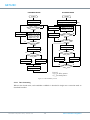
The pointer field has also been made writable for maximum flexibility but care should be taken when
writing to the descriptor pointer register. It should never be touched when a transmission is active.
The final step to activate the transmission is to set the transmit enable bit in the control register. This
tells the GRETH that there are more active descriptors in the descriptor table. This bit should always
be set when new descriptors are enabled, even if transmissions are already active. The descriptors
must always be enabled before the transmit enable bit is set.
17.3.3 Descriptor handling after transmission
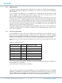
When a transmission of a packet has finished, status is written to the first word in the corresponding
descriptor. The Underrun Error bit is set if the FIFO became empty before the packet was completely
transmitted while the Alignment Error bit is set if more collisions occurred than allowed. The packet
was successfully transmitted only if both of these bits are zero. The other bits in the first descriptor
word are set to zero after transmission while the second word is left untouched.
The enable bit should be used as the indicator when a descriptor can be used again, which is when it
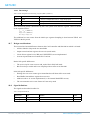
has been cleared by the GRETH. There are three bits in the GRETH status register that hold transmission status. The Transmitter Error (TE) bit is set each time an transmission ended with an error (when
at least one of the two status bits in the transmit descriptor has been set). The Transmitter Interrupt
(TI) is set each time a transmission ended successfully.
The transmitter AHB error (TA) bit is set when an AHB error was encountered either when reading a
descriptor or when reading packet data. Any active transmissions were aborted and the transmitter
was disabled. The transmitter can be activated again by setting the transmit enable register.
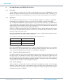
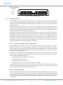
17.3.4 Setting up the data for transmission
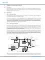
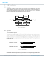
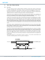
The data to be transmitted should be placed beginning at the address pointed by the descriptor address
field. The GRETH does not add the Ethernet address and type fields so they must also be stored in the
data buffer. The 4 B Ethernet CRC is automatically appended at the end of each packet. Each descriptor will be sent as a single Ethernet packet. If the size field in a descriptor is greater than 1514 B, the
packet will not be sent.
17.4
Rx DMA interface
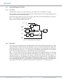
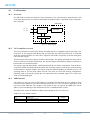
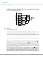
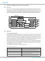
The receiver DMA interface is used for receiving data from an Ethernet network. The reception is
done using descriptors located in memory.
17.4.1 Setting up descriptors
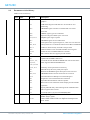
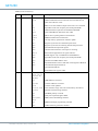
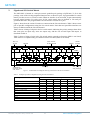
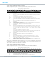
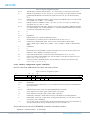
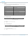
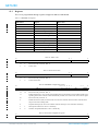
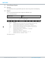
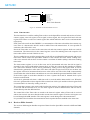
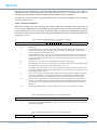
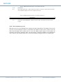
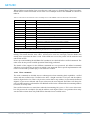
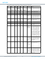
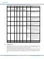
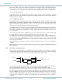
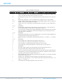
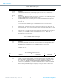
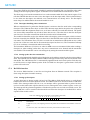
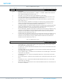
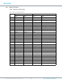
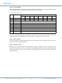
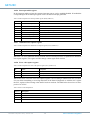
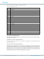
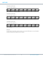
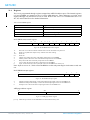
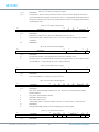
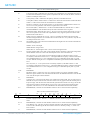
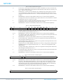
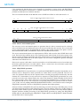
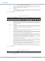
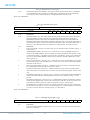
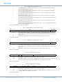
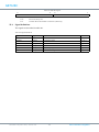
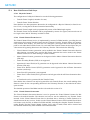
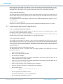
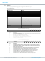
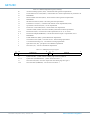
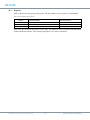
A single descriptor is shown in table 109 and 110. The address field should point to a word-aligned
buffer where the received data should be stored. The GRETH will never store more than 1514 B to the
buffer. If the interrupt enable (IE) bit is set, an interrupt will be generated when a packet has been
received to this buffer (this requires that the receiver interrupt bit in the control register is also set).
The interrupt will be generated regardless of whether the packet was received successfully or not. The
Wrap (WR) bit is also a control bit that should be set before the descriptor is enabled and it will be
explained later in this section.
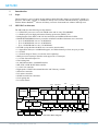
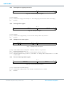
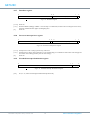
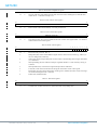
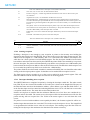
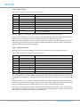
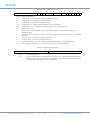
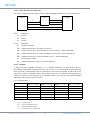
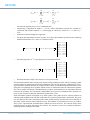
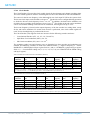
Table 109. GRETH receive descriptor word 0 (address offset 0x0)
31
19 18 17 16 15 14 13 12 11 10
RESERVED
LE OE CE FT AE IE WR EN
0
LENGTH
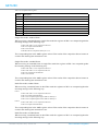
31: 19
RESERVED
18
Length error (LE) - The length/type field of the packet did not match the actual number of received
bytes.
17
Overrun error (OE) - The frame was incorrectly received due to a FIFO overrun.
GR712RC-UM, Nov 2015, Version 2.6
129
www.combham.com/gaisler