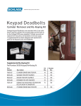
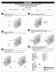
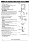
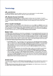
1
Real Security Sets You Free. ™
Rekeying
Manual
For use with
Keying Kits
40-132, 40-134
& 38-030
®
Real Security Sets You Free. ™
Rekeying is easy with Schlage
Schlage engineers its locks for professional-grade durability, remarkable
beauty and easy rekeying steps. Whether you’re rekeying a lockset or
deadbolt, Schlage makes it simple with step-by-step instructions and
pictures to help you complete the job. It’s just one more reason that
Schlage is the number one selling retail brand.*
*2004 Scout Market Intelligence Report
Contents
3-4
Rekeying Kits
5-10
Rekeying F, FA & FB Series Residential Front Entry Sets, Keyed Knobs
and Levers
11-16
Rekeying BE & FE Series Residential Electronic Keypads and Deadbolts
17-20
Rekeying A & AL Medium Duty Series Levers
21-26
Rekeying B300 & BA300 Series Residential Deadbolts
27-28
Rekeying S Light Duty Commercial Series Levers
29-32
Rekeying B100, BC100 & BR200 Series Deadbolts
33-36
Rekeying B200 Series Deadbolts
37-38
Using Key Gauge/ Reinserting Disengaged Pins and Springs
39
Glossary
Rekeying Kits
®
Real Security Sets You Free. ™
Schlage Keying Kits provide
everything you need to get
the job done.
Keying Kit 40-1 Includes
everything you need to rekey the most
popular Schlage knobs, levers and BSeries deadbolts. Includes bottom pins,
top pins, springs, cylinder caps, cap
pins, cap pin springs, B-Series deadbolt
tailpieces, key gauge, plug follower and
cap removal tool.
Keying Kit 40-14
Contains all of the basic
materials to rekey most
Schlage knobs and levers.
Includes bottom pins, top
pins, springs, cylinder caps,
cap pins, key gauge and
plug follower.
Rekeying Kits
– continued
Supplemental Keypad
Lock ReKeying Kit
8-00 Contains all of the
basic replacement materials for
rekeying Schlage keypad locks
and deadbolts. Includes cylinder
driver bar, extra screws, tailpiece
washers, spacers, and retainers.
4
®
Real Security Sets You Free. ™
®
Real Security Sets You Free. ™
F, FA & FB-Series
Rekeying
F, FA & FB-Series
Residential Front
Entry Sets, Keyed
Knobs and Levers
F, FA & FB-Series
– continued
®
Real Security Sets You Free. ™
1 Lock Disassembly
1A
1B
B Depress knob/lever
A Insert key into knob
1E
D Rotate key back 90°
to original position and
remove key.
C Use your thumb and
catch using tab on key
gauge and pull knob/
lever off of knob catch.
or lever cylinder plug,
rotate 90°.
1D
1C
forefinger to apply
pressure on the rose
and pull knob/lever
off spindle.
1F
E To remove the cylinder, first ensure that the keyway on the plug
is facing upright. Next, allow the tail end of the cylinder to drop
down slightly so that the top of the face of the cylinder sits in at an
angle. The cylinder should not fall completely into the body of the
knob (like picture E, not like picture F).
®
Real Security Sets You Free. ™
F, FA & FB-Series
– continued
Cylinder Removal
CAUTION: To REMovE ThE
CyLINDER ThRoUGh ThE REAR
oF ThE KNoB/LEvER, yoU WILL
NoT NEED To USE MoRE ThAN
5 PoUNDS oF FoRCE (oR ThE
AMoUNT oF FoRCE REqUIRED
To PUSh AN ELEvAToR BUTToN).
IF yoU REqUIRE MoRE FoRCE,
ThE CyLINDER IS NoT ALIGNED
CoRRECTLy FoR REMovAL.
PLEASE REFER To STEPS E AND F
FoR CoRRECT ALIGNMENT.
A
B
A Carefully push the
cylinder out of the back
of the knob/lever by
applying pressure to the
top of the cylinder
plug face.
B The cylinder will
automatically compress
and exit the rear of the
knob/lever through
the shank of the
knob/lever.
F, FA & FB-Series
– continued
®
Real Security Sets You Free. ™
Cylinder Repinning - Method 1
Method 1:
(RECoMMEnDED)
B
A
B Insert & rotate the key 90°
A Using U-Shaped
and insert the end of the
plug follower into the rear
of the cylinder housing
- pushing the plug out the
front of the housing.
portion of key gauge,
press forward to
remove C-Clip cylinder
retaining ring.
C
D
C Keep the plug follower
in the body to keep the
top pins and springs from
blowing. Dump the bottom
pins from the plug.
8
E
D Load new bottom
pins into the plug that
correspond to the new
key combination.
E Re-insert the plug back
into the housing and push
the plug follower back out.
Finally, re-insert the C-Clip
cylinder retaining ring onto
the back of the plug.
®
F, FA & FB-Series
– continued
Real Security Sets You Free. ™
Cylinder Repinning - Method Method : The compressible
cylinders can also be rekeyed from
the top of the cylinder by removing
the stainless steel cap – and dumping
the bottom pins, top T-Pins, and top
springs from the cylinder. To rekey,
simply insert new bottom pins into
the holes on the top of the cylinder
and then re-insert the top T-pins and
springs on top of the bottom pins.
Finally, attach a NEW stainless steel
cap to the top of the cylinder body by
aligning the holes in the top cap with
the holes in the springs. Each spring
B
A
A Using a screwdriver
B Dump contents from
or other small edge
carefully pry off the
steel cap from the top
of the cylinder.
should encircle each hole on the cap.
the top of the cylinder
(springs, top pins and
bottom pins).
Top
Bottom
C
D
C Align the holes in the plug with
the holes in the housing. Load
new bottom pins and re-load
the top T-Pins (see inset for
correct insertion direction). Reload the springs over the top of
the thin part of the top T-Pins.
D Attach a NEW steel cap
onto the top of the housing
- aligning each spring with
the hole in the cap. The
teeth of the cap should also
align with the grooves on
the housing.
F, FA & FB-Series
– continued
®
Real Security Sets You Free. ™
4 Lock Reassembly
4A
4C
4B
A Compress the cap and reinsert the cylinder into the
shank of the knob (plug
face first) aligning the cap
with the slot in the sleeve
inside the knob.
4D
D If necessary, depress
knob catch and slide
knob on until the catch
pops into the slot on
knob. Rotate key 90°
and remove key.
10
B With the cap aligned
with the slot, push the
cylinder the rest of the
way into the knob.
C Insert key into cylinder
plug, rotate 90°. Line
up slot on the shank of
the knob with catch on
spindle and slide knob
onto spindle.
Real Security Sets You Free. ™
BE & FE Electronic Series
Rekeying
BE & FE Series
Residential Electronic
Keypads and Deadbolts
11
BE & FE Electronic Series
– continued
Real Security Sets You Free. ™
1 Keypad Lock Cylinder Removal
1A
1B
FE and FE cylinder
removal instructions
1C
B Remove cylinder
A Remove access panel
from keypad assembly.
C Remove cylinder cap,
retaining screw and
cylinder.
washer, tailpiece, pin,
and spring.
Remove the Cylinder Plug
A
B
A Insert key and turn
clockwise to two o’clock
position. Place flat end
of follower against back
of cylinder plug.
1
C
B CAUTION: To avoid top pins
springing out of cylinder
shell, push follower all the
way through in one careful,
continuous motion. When
completed, shell should be
near center of follower.
NoTE: IF ThE ToP PINS AND SPRINGS
DISENGAGE, PLEASE SEE PAGE 38.
C Dump bottom pins
from plug and remove
old key. Discard old
pins and keys.
BE & FE Electronic Series
– continued
Real Security Sets You Free. ™
Load new Bottom Pins
A
B
A Use numbers on key bow
IMPoRTANT! MAKE SURE ThAT
ALL PINS ARE FLUSh WITh
ToP oF PLUG, FoRMING A
PERFECT ShEAR LINE. IF ANy
ExTEND ABovE oR BELoW
ThE SURFACE, REPLACE WITh
CoRRECT SIzES.
B Load new bottom pins
or use key gauge (see page
38) to determine new key
combination. Insert new
key all the way until it stops
against plug face.
(pointed end down) into
plug with pins from kit
corresponding to new key
combination.
4 Keypad Lock Reassembly
4A
4B
4C
A Insert key and turn clockwise
B Install spring, pin,
to two o’clock position. Place
flat end with square notch of
follower against back of plug.
tailpiece, washer,
and cylinder cap.
IMPORTANT! MAKE SURE
FoLLoWER NoTCh IS IN
hoRIzoNTAL (NINE AND ThREE
o’CLoCK) PoSITIoN.
NOTE: MAKE SURE
FoLLoWER NoTCh IS IN
hoRIzoNTAL (NINE AND
ThREE o’CLoCK) PoSITIoN.
C Reinstall cylinder as shown.
NOTE: RoTATE TAILPIECE To
vERTICAL PoSITIoN AS ShoWN. MAKE
SURE ARRoW oN ACCESS PANEL IS
PoINTING To NORMAL PoSITIoN.
D Use FE575 or FE595
Installation Sheet to
Install Lock.
1
BE & FE Electronic Series
– continued
Real Security Sets You Free. ™
1 Keypad Deadbolt Cylinder Removal
1A
1B
A Remove backplate
from outside keypad
assembly.
1D
D Remove cylinder cap,
tailpiece, pin, and
spring.
14
BE cylinder
removal instructions
1C
B Remove cylinder from
thumbturn.
C Remove retainer, block,
and disc from cylinder.
BE & FE Electronic Series
– continued
Real Security Sets You Free. ™
Remove the Cylinder Plug
A
B
A Insert key and turn
C
B CAUTION: To avoid top pins
clockwise to two o’clock
position. Place flat end
of follower against back
of cylinder plug.
springing out of cylinder
shell, push follower all the
way through in one careful,
continuous motion. When
completed, shell should be
near center of follower.
C Dump bottom pins
from plug and remove
old key. Discard old
pins and keys.
NoTE: IF ThE ToP PINS AND SPRINGS
DISENGAGE, PLEASE SEE PAGE 38.
Load new Bottom Pins
A
B
A Use numbers on key bow
or use key gauge (see page
38) to determine new key
combination. Insert new
key all the way until it stops
against plug face.
B Load new bottom pins
(pointed end down) into
plug with pins from kit
corresponding to new key
combination.
IMPoRTANT! MAKE SURE ThAT
ALL PINS ARE FLUSh WITh
ToP oF PLUG, FoRMING A
PERFECT ShEAR LINE. IF ANy
ExTEND ABovE oR BELoW
ThE SURFACE, REPLACE WITh
CoRRECT SIzES.
1
BE & FE Electronic Series
– continued
Real Security Sets You Free. ™
4 Keypad Deadbolt Reassembly - cont.
4A
BE cylinder
removal instructions
4B
A Install spring, pin
tailpiece, and cylinder
cap.
B Install disc, block, and
retainer.
4C
C Reinstall cylinder as
shown.
NOTE: MAKE SURE ToP
oF CyLINDER IS PoINTING
ToWARDS KEyPAD.
D Use BE365 Installation
Sheet to Install Lock.
1
®
Real Security Sets You Free. ™
A & AL Medium Duty Series
Rekeying
A & AL Medium
Duty Series Knobs
and Levers
1
A & AL Medium Duty Series
– continued
®
Real Security Sets You Free. ™
1 Remove the Knob or Lever
1A
1B
A Put key into cylinder
1C
B Using tab on key
(with teeth of key
facing up) and turn key
clockwise one quarter
turn to three o’clock
position.
gauge, depress knob/
lever retainer through
hole in knob/lever
shank.
B
A
A Push cylinder forward B Remove key from cylinder and
until knob sleeve
disengages from back
of knob. Remove sleeve
and set it aside.
18
forefinger to apply
pressure on rose and
pull knob/lever off
spindle.
Remove the Cylinder
Retaining Clip
Remove the Cylinder
A
C Use thumb and
remove cylinder from back of
knob.
B
A Engage U-shaped
portion of key
gauge with “C”
shaped clip on
back of cylinder.
B Press key gauge
forward to
disengage and
remove clip.
®
A & AL Medium Duty Series
– continued
Real Security Sets You Free. ™
4 Remove the Cylinder Plug
4A
4B
A Insert key and turn
4C
B hold follower firmly against plug and
clockwise to two
o’clock position.
hold slotted end of
follower against back
of cylinder plug.
carefully slide it through cylinder shell
until plug and front of follower have
passed completely through cylinder shell.
IMPORTANT! Do NoT PULL FoLLoWER
CoMPLETELy ThRoUGh CyLINDER.
Cylinder shell should end up
near center of follower. Set
these items aside, noting
which end of shell is front
end.
C Dump bottom pins from plug
and remove old key. Discard
old pins and keys.
Load new Bottom Pins
ShEAR LinE
A
IMPORTANT: MAKE SURE ALL
NEW PINS ARE FLUSh WITh ToP
oF PLUG, FoRMING A PERFECT
ShEAR LINE. IF ANy FALL BELoW
oR ExTEND ABovE ShEAR LINE,
REPLACE WITh CoRRECT SIzES.
B
A Use numbers on key bow
or use key gauge (see page
38) to determine new key
combination. Insert new
key all the way until it stops
against plug face.
B Load new bottom pins
(pointed end down)
from keying kit that
correspond to new key
combination.
1
A & AL Medium Duty Series
– continued
®
Real Security Sets You Free. ™
Reinsert the Cylinder Plug
A
B
A Engage back of
plug in follower
notch and turn
slightly relative
to cylinder shell.
Gently push plug
into shell, pushing
follower out.
Reassemble the Knob
A
B Reattach retaining
clip to back of
cylinder and snap
into place.
IMPORTANT: KEy IS STILL IN
PLUG AT ThIS PoINT! REMovE
KEy oNLy WhEN “C” CLIP IS
SNAPPED BACK INTo PLACE.
B
A Align cylinder with
opening on rear
of knob and insert
cylinder, keyway
first.
B Place sleeve onto
rear of knob, align
notched area of sleeve
with knob opening,
and press into place.
8 Reattach the Knob
8A
8B
A Insert key into cylinder and
0
turn it clockwise 1/4 turn to
the three o’clock position. Align
notch in attached sleeve with
groove on spindle and slide
knob toward sprig-loaded knob
retainer.
B Depress retainer with tab on key gauge
or other suitable tool and slide knob
until retainer snaps into engagement.
Turn key back and forth to verify smooth
operation and retainer engagement. A
clicking sound indicates that you’ve
done the job correctly.
Real Security Sets You Free. ™
B00 & BA00-Series
Rekeying
B00 & BA00-Series
Residential Deadbolts
1
B00 & BA00-Series
– continued
Real Security Sets You Free. ™
1 Preparation
REtA
t inER
tA
CRAnK
1A
1B
A Remove adapter ring (For
1C
B Lift crank assembly and
1½˝ opening only). Place
cylinder assembly face down
on smooth surface.
retainer over bumps with
flat blade screwdriver and
remove.
Remove the Cylinder Cap
A
B
A Engage teeth of cylinder cap
removal tool with scallops in
cylinder cap as shown. Push
tool down against slight spring
pressure and unscrew cap.
B Remove cap, tailpiece, washer,
cap pin and spring from back
of plug and set aside.
NOTE:To REMovE TINy CAP PIN SPRING,
TURN CyLINDER ASSEMBLy UPSIDE
DoWN AND GENTLy TAP oN TABLE.
C Remove black retainer
and crank.
B00 & BA00-Series
– continued
Real Security Sets You Free. ™
Remove the Cylinder Plug
A
B
A Insert key and turn
C
B CAUTION: To avoid top pins
clockwise to two o’clock
position. Place flat end of
follower against back of
cylinder plug.
springing out of cylinder shell,
push follower all the way through
in one careful, continuous
motion. When completed, shell
should be near center of follower.
C Dump bottom pins
from plug and remove
old key. Discard old
pins and keys.
NoTE: IF ThE ToP PINS AND SPRINGS
DISENGAGE, PLEASE SEE PAGE 38.
4 Load new Bottom Pins
ShEAR LinE
4A
4B
A Use numbers on key bow
or use key gauge (see page
38) to determine new key
combination. Insert new
key all the way until it stops
against plug face.
B Load new bottom pins
(pointed end down) into
plug with pins from kit
corresponding to new key
combination.
IMPoRTANT! MAKE SURE ThAT
ALL PINS ARE FLUSh WITh ToP
oF PLUG, FoRMING A PERFECT
ShEAR LINE. IF ANy ExTEND
ABovE oR BELoW ThE SURFACE,
REPLACE WITh CoRRECT SIzES.
B00 & BA00-Series
– continued
Real Security Sets You Free. ™
Reinsert Plug
A
B
A With plug turned slightly,
place back of plug against
flat end of follower and push
follower out smoothly by
pushing plug into shell.
4
B Place thumb against
plug face and carefully
pull out key.
NOTE:Do NoT PULL KEy
oUT UNLESS SECURELy
hoLDING PLUG FACE WITh
yoUR ThUMB. ThIS KEEPS
PLUG IN PLACE.
B00 & BA00-Series
– continued
Real Security Sets You Free. ™
Cylinder Cap Reassembly
A
B
A Place cylinder assembly
on smooth surface.
Insert cap pin spring,
then cap pin into small
hole in back of plug.
C
B Place tailpiece
with washer on top
of plug. Be sure
opening in washer
straddles cap pin.
C Position cylinder cap
and screw into place
with cylinder cap tool,
but not tight. Cap pin
should pop into one of
the scallops in cap.
test key by turning
left and right, and
removing it. if key is
hard to turn, loosen
cap one notch by
turning counter
clockwise. if key
won’t come out,
tighten cap by turning
clockwise. Repeat this
test until operation is
smooth.
B00 & BA00-Series
– continued
Real Security Sets You Free. ™
Reassemble Crank Assembly
REt
RE
tAin
inER
ER
CRAn
CRA
nK
tAiLP
LPiiECE
A
B
A Place crank into
B Push retainer and crank
retainer and slide onto
tailpiece.
combination, onto
tailpiece, until it stops
against cylinder cap.
C
C Replace adapter ring
with the words facing
you. (Leave this off if
installing lock into 1½˝
diameter hole.)
to rekey inside
cylinder of B
deadbolts, simply
repeat steps through .
®
Real Security Sets You Free. ™
S Light Duty Series
S Light Duty
Commercial
Series Levers
S Light Duty Series
– continued
®
Real Security Sets You Free. ™
S Light Duty Commercial Levers
A
B
A Insert key and turn it
clockwise 90° to three
o’clock position.
C
B Using tab on key
C Remove key and remove
gauge, depress retainer
and remove knob or
lever.
cylinder. For S-Series
locksets, notice sleeve
around cylinder and
remove sleeve.
NoTE: ThIS SLEEvE IS MERELy A
SPACER AND DoES NoT AFFECT
ThE REKEyING PRoCESS.
To REKEy — FoLLoW
INSTRUCTIoNS 3A – 6B
STARTING oN PAGE 18.
D
D When reassembling, slide cylinder back into lever,
keyway first. Align button on chassis with hole in knob
or lever shank and slide into place.
Reinsert key, turn it 90° to three o’clock position and
press knob or lever back into place.
8
Real Security Sets You Free. ™
B100, BC100 & BR00-Series
B100, BC100 &
BR00-Series
Deadbolts
B100, BC100 & BR00-Series
– continued
Real Security Sets You Free. ™
1 Preparation
1A
1A
B100/BC100
BR00
A Remove cylinder assembly from
A Remove the attached tailpiece from
its collar. Place cylinder face
down on a smooth surface.
the back of the cylinder and place the
housing face down on a smooth surface.
Remove the Cylinder Cap
ThE PhoToGRAPhS IN
ThIS SECTIoN DEPICT
B100 hoUSINGS;
hoWEvER, ThE BC100
AND BR200 SERIES
CyLINDERS REKEy ThE
SAME WAy.
A
B
A Align scallops of cylinder cap
with teeth on cylinder cap
removal tool. Push tool down
against slight spring pressure.
Unscrew cap and remove it.
0
B Remove cap, washer, pin and
spring from back of cylinder
plug and set aside.
NoTE: IF CAP REMovAL TooL IS LoST,
USE TAB oN KEy GAGE oR oThER
SMALL TooL To DEPRESS CAP PIN AND
UNSCREW CAP WITh FINGERS.
Real Security Sets You Free. ™
Remove the Cylinder Plug
A
B
A Insert key and turn clockwise
IMPoRTANT! MAKE SURE
FoLLoWER NoTCh IS IN hoRIzoNTAL
(NINE AND ThREE o’CLoCK)
PoSITIoN.
4 Remove Bottom Pins
4A
B holding follower firmly against
to two o’clock position. Place
flat end with square notch of
follower against back of plug.
B100, BC100 & BR00-Series
– continued
back of plug, carefully push
follower through cylinder shell.
Support front of plug so it does
not fall as it is pushed out.
Cylinder shell should end up in
center of follower. Set aside.
A Dump bottom pins from plug and
remove old key. Discard old pins
and keys.
NoTE: IF ToP PINS AND SPRINGS
DISENGAGE FRoM CyLINDER, SEE PAGE 35.
Load new Bottom Pins
ShEAR LinE
IMPORTANT! ALL
PINS MUST BE
FLUSh WITh ToP
oF PLUG, FoRMING
A PERFECT ShEAR
LINE. IF ANy FALL
BELoW oR ExTEND
ABovE ShEAR LINE,
REPLACE WITh
CoRRECT SIzES.
A
B
A Use numbers on key bow or use key
gauge (see page 38) to determine new
key combination. Insert new key all the
way until it stops against plug face.
B Load new bottom pins (pointed end down) into
plug with pins from keying kit corresponding to
new key combination.
1
B100, BC100 & BR00-Series
– continued
Real Security Sets You Free. ™
Reinserting Cylinder Plug
A
B
A Again, place flat end of
B Insert key and place thumb
follower against back of plug.
Carefully push plug into shell,
pushing follower out.
against plug face. CAREFULLy
pull key out, leaving plug locked
in shell.
Cylinder Cap Reassembly
A
B
A Place cylinder face
down on a smooth
surface. Insert cap pin
spring and cap pin into
small hole in back of
plug.
C
B Place washer on back of
C Screw cylinder cap back on with cap removal
plug raised side up with
notch around cap pin.
tool until cap is all the way on but not tight.
Test cylinder by inserting key, turning both
directions, and removing it. If key turns hard
or not at all, cap may be too tight. If key
won’t come out without pressing against
plug face, cap is too loose. Adjust cap
accordingly.
®
Real Security Sets You Free. ™
B00-Series
B00-Series
Deadbolts
B00-Series
– continued
®
Real Security Sets You Free. ™
Remove Plug Retainer
1 Preparation
1A
1B
A Remove cylinder
assembly from rear
of collar assembly.
A
B Remove phillips head
screw and remove
cylinder from its housing.
A To remove “C-Shaped” retainer, align
tailpiece with half-round notch in
key gauge (40-104) as shown. Push
key gauge against C-clip until it pops
off. Remove tailpiece.
Remove the Cylinder Plug
A
B
A Insert key and turn
clockwise to two o’clock
position.
Donotremovethisplug.
4
C
B To remove plug, use notched
end of follower (as shown).
Align notched end of follower
with cylinder plug.
NOTE: IF ToP PINS AND SPRINGS DISENGAGE
FRoM CyLINDER, SEE PAGE 35.
C CAUTION: To avoid top pins
springing out, push follower
all the way through in one
continuous careful motion.
When completed, shell should
be near center of follower.
®
B00-Series
– continued
Real Security Sets You Free. ™
4 Remove Bottom Pins
Load new Bottom Pins
ShEAR LinE
A
4A
A Dump bottom pins
B
A Use numbers on key bow or
from plug and remove
old key. Discard old
pins and keys.
use key gauge (see page 38) to
determine new key combination.
Insert new key all the way until
it stops against plug face.
Reinserting Cylinder Plug
A
B Load new bottom pins into
plug with pins from keying kit
to correspond with new key
combination. Begin with pin
chamber closest to key bow.
IMPORTANT! MAKE SURE ALL PINS ARE
FLUSh WITh ToP oF PLUG, FoRMING
A PERFECT ShEAR LINE. IF ANy FALL
BELoW oR ExTEND ABovE ShEAR LINE,
REPLACE WITh CoRRECT SIzES.
B
A Place notched end of follower
against back of plug. hold
plug turned to the two o’clock
position with the key inserted.
B Carefully push plug into
shell, pushing follower out
into other hand. DONOT
REMOVEKEY!
B00-Series
– continued
®
Real Security Sets You Free. ™
Cylinder Cap Reassembly
A
B
A Reinstall C-shaped plug
retainer and tailpiece.
Remove key.
Be sure retainer does not
block key slot on bottom
of plug.
C
B Place cylinder into its
housing.
C Secure cylinder in place
with Phillips screw.
Real Security Sets You Free. ™
Determining Combinations
Using the
Key Gauge
to Determine
Combinations
Determining Combinations
– continued
Real Security Sets You Free. ™
Using the Key Gauge to
Determine Combinations
1 With key cuts facing up, slide key into opening of key
gauge near number “0” and slide to first cut (notch)
from key bow.
Slide key left until it stops on a number.
Write down number and proceed to next cut.
4 Repeat until all cuts have a corresponding number, from
bow to tip of key. This five or six-digit number is the key
combination or “bitting”.
IMPORTANT! IF ThE KEy LANDS BETWEEN TWo NUMBERS, PICK ThE
LoWER NUMBER (ShALLoWER CUT).
if top Pins and Springs Become
Disengaged...
1 Insert square notched end of follower into cylinder shell
from rear.
Install spring into back chamber and balance top pin
(#3) on top of spring.
Using follower groove as a guide, push pin into its
chamber against spring pressure with flat edge of
tweezers or small flat blade screwdriver.
4 Slide follower forward to hold pin and spring in place.
Repeat until all chambers are loaded.
8
®
Real Security Sets You Free. ™
Glossary
ANSI
American National Standards Institute.
backset
The distance from the edge of door to the center line of prep.
bottompin
A bullet-shaped tumbler that comes in a variety of lengths that correspond to the
depths of the key cuts.
chassis
The body of the lock itself, without any trim.
cylinder
The portion of a lock comprised of the plug, shell, pins (tumblers) and springs. A
properly cut key allows the plug to rotate the tailpiece or drive mechanism which
unlocks the lock.
hand
The direction a door swings, always referenced from the outside.
housing
A larger portion of some cylinder assemblies which encases the cylinder (plug and
shell).
latchbolt
A spring operated bolt with a beveled face to permit latching action when door
closes.
masterpin
A cylindrical shaped tumbler which is flat on both ends, placed between the top and
bottom pin to create an additional shear line.
pintumbler
Today’s standard tumbler mechanism consists of a series of bottom pin,
mechanism
top pin and spring for each cut (notch) of the key.
pintumblers
Small sliding pins in a lock cylinder that work against coil springs. They prevent
the cylinder plug from rotating unless all are aligned simultaneously by cuts of the
proper depths in the key.
plug
The portion of a cylinder which contains the keyway and which rotates with the key.
rose
A circular trim plate attached to the door under the knob or lever.
shearline
The area where the top surface of the cylinder plug and inside surface of the shell
meet, and the height to which the bottom pins must be raised by the key in order to
rotate the plug.
shell
The portion of the cylinder immediately surrounding the plug.
strike
The metal plate recessed in the frame that receives latch or bolt when the door is
closed.
toppin
A cylindrical shaped tumbler which is flat on both ends and is installed directly
under a coil spring in its chamber.
tailpiece
A usually flat actuator which extends from the back of the cylinder plug and
engages in the lock to operate the latch or bolt.
Administrative Offices
111 Congressional Blvd, Suite 200
Carmel, IN 46032
(800) 847-1864
Customer Service
14505 West 100th Street
Lenexa, KS 66215
Order Processing
(800) 847-1864
Schlage Distribution
Service Center
P.O. Box 2970
Shawnee Mission, KS 66201-1370
14505 West 100th Street
Lenexa, KS 66215
(800) 847-1864
(913) 541-8881
FAX (800) 365-5625
International Division
Ingersoll Rand Security Technologies
1076 Lakeshore Road East
Mississauga, Ontario L5E 1E4
Canada
(877) 590-4734
(905) 403-1800
FAX (905) 270-1413
Ingersol Rand’s Security Technologies Sector is a leading global provider of products and services that make
environments save, secure and productive. The sector’s market-leading products include electronic and
biometric access-control systems; time-and-attendance and personnel scheduling systems; mechanical
locks; portable security; door closers, exit devices, architectural hardware, and steel doors and frames; and
other technologies and services for global security markets.
800-847-1864 Fax 800-452-0663
www.schlage.com
www.ingersollrand.com
©2007 Ingersoll-Rand Company P513-325 Rev 1/07