1
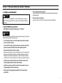
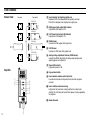
96M10789
Instruction
Manual
Laser Thrubeam
Photoelectric Sensor
LX2(W) Series
CONTENTS
SAFETY INFORMATION FOR LX2 SERIES
SAFETY Information for LX2 series ....................................................... 2
Precautions for Handling the LX2(W) Series ......................................... 3
Method for Insulating the Sensor Head from the Mounting Surface ...... 4
Safety Precautions on Laser Product .................................................... 5
Part Names .......................................................................................... 10
Connections ......................................................................................... 11
Alignment of Optical Axis ..................................................................... 12
Tolerance Setting ................................................................................. 14
Hints on Correct Use ............................................................................ 15
Specifications ....................................................................................... 16
Dimensions .......................................................................................... 18
WARRANTY ........................................................................................ 20
This manual describes how to install the LX2 Series as well as its
operating procedures and precautions. Please read this manual carefully
for your safety.
CAUTION
Avoid mounting the sensor head in a place where electrostatic potential
can build up or which is subject to EMI. If any electrostatic potential
reaches the sensor head, the sensor's laser diode may be damaged. If
such a possibility exists, ground the place where the sensor head is to
be mounted, and insert insulating material between the sensor head and
the mounting surface so that the sensor will be static-free.
See page 3 and 4 for further information.
Symbols
The following symbols alert you to important messages. Be sure to read
these messages carefully.
WARNING
Failure to follow instructions may lead to injury.
(electric shock, burn, etc.)
CAUTION
Failure to follow instructions may lead to product
damage.
Note
Provides additional information on proper operation.
General Safety precautions
• At startup and during operation, be sure to monitor the functions and
performance of the LX2 series.
• We recommend that you take substantial safety measures to avoid
any damage in the event a problem occurs.
• Do not open or modify the LX2 series or use it in any way other than
described in the specifications.
• When the LX2 series is used in combination with other instruments,
functions and performance may be degraded, depending on operating
conditions and the surrounding environment.
• Do not use this product for the purpose to protect a human body or a
part of human body.
• This product is not intended for use as explosion-proof product. Do
not use this product in a hazardous location and/or potentially
explosive atmosphere.
2
PRECAUTIONS FOR HANDLING THE LX2(W) SERIES
The LX2 series uses a semiconductor laser diode for the light source.
When using the sensor, be sure to follow the precautions given below.
• Before connecting the sensor head to the controller, be sure to turn off
the controller’s power supply.
Otherwise, noise generated due to chattering at the connection may
damage the semiconductor laser diode.
• Before performing maintenance or inspection work, be sure to turn off
the power supply.
Performing maintenance or inspection work with the power on may
damage the sensor.
• The sensor head is grounded through its housing. Therefore, if the
sensor head is mounted on a surface to which noise is conveyed, the
noise may cause the sensor to malfunction or may damage the
semiconductor laser diode.
In such a case, insulate the sensor head from the mounting surface.
(For the method for insulating the sensor head from the mounting
surface, see page 4.)
• Static electricity on the human body or around the sensor head may
damage the semiconductor laser diode.
Pay special attention to prevent electrostatic discharge when connecting the sensor head and controller. When connecting them, be sure to
use an anti-static wrist strap.
• Do not install the sensor head where water, oil, organic solvent, etc.
may splash it.
Failure to follow this may cause not only unstable measurement but
may also damage the sensor head due to entry of the liquid inside the
unit.
• Do not install the power supply cable or sensor head cable in the
same conduit as high voltage lines or power lines.
Failure to follow this may cause the sensor to malfunction due to noise
interference or may damage the semiconductor laser diode.
• Noise conveyed through the power supply may cause a malfunction or
damage.
In such a case, use an insulating transformer for the power supply to
stabilize the DC power supply. When using a switching regulator, be
sure to ground the frame-ground and ground terminals.
3
METHOD FOR INSULATING THE SENSOR HEAD FROM THE MOUNTING SURFACE
Method 1: When using metallic screws to mount the
sensor head
Fill up the hole with plastic.
Metallic
screw
Method 2: When using plastic screws to mount the
sensor head
Plastic screw
Plastic plate
Plastic plate
5 mm or more
Mounting stay
Use an insulating plastic plate with a thickness of 5 mm or more. Though
the kind of plastic is not specified, plastic that withstands a higher
voltage is preferred (e.g. Teflon, etc.).
Make a hole in the two places on the plastic plate, and insert screws
from the bottom surface of the plate to fix the sensor head to the plate.
Fill up the holes with silicone or other plastic to prevent the head of the
screws from coming into contact with the surface of the mounting stay.
4
5 mm or more
Mounting stay
Use an insulating plastic plate with a thickness of 5 mm or more. Though
the kind of plastic is not specified, plastic that withstands a higher
voltage is preferred (e.g. Teflon, etc.).
Do not use the acrylic plastic screws included with the sensor. Since
they do not provide satisfactory strength, the sensor head may be
dislocated after mounting.
SAFETY PRECAUTIONS ON LASER PRODUCT
3) Aperture label
1. Classification
Model
FDA(CDRH) 21CFR Part 1040.10
IEC/EN 60825-1
DIN EN 60825-1
LX2-11(W) LX2-12(W)
Class III b
Class 3B
Class 3B
LX2-13(W) LX2-110(W)
Class I
Class II
Class 1
Class 1
IEC Class 3B
AVOID EXPOSURE
INVISIBLE LASER
RADIATION IS EMITTED
FROM THIS APERTURE.
FDA Class II
2. Labels
IEC (French) Classe 3B
AVOID EXPOSURE
1) FDA(CDRH) Warning labels
FDA(CDRH) Class II
FDA Class I
LASER RADIATION
IS EMITTED FROM
THIS APERTURE.
FDA(CDRH) Class IIIb
FDA Class IIIb
DIN Klasse 3B
AVOID EXPOSURE
LASER RADIATION-DO NOT
STARE INTO BEAM
INVISIBLE LASER RADIATION
AVOID DIRECT EXPOSURE
TO BEAM
SEMICONDUCTOR LASER 670nm
MAXIMUM OUTPUT 0.8mW
PULSE DURATION 30 µSEC.
CLASS II LASER PRODUCT
SEMICONDUCTOR LASER 780nm
MAXMUM OUTPUT 3mW
PULSE DURATION 30 µSEC.
CLASS IIIb LASER PRODUCT
INVISIBLE LASER
RADIATION IS EMITTED
FROM THIS APERTURE
2) IEC Explanatory/Warning labels
IEC Class 1
CLASS1 LASER PRODUCT
IEC Class 3B
IEC (French) Classe 1
APPAREIL Á LASER DE CLASSE 1
IEC (French) Classe 3B
DIN Klasse 1
LASER KLASSE 1
DIN Klasse 3B
5
3. Label location
▲
SAFETY PRECAUTIONS ON LASER PRODUCT
(
IEC/DIN
LX2-13 (W)/LX2-110 (W)
: Aperture)
FDA Warning labels are attached to the sensor head as shown below.
When using this product in the countries and/or regions other than U.S., use
the IEC warning/explanatory label in the package of this product.
In this case, it can be affixed on the FDA (CDRH) warning label, which has
already been affixed to this product.
FDA
LX2-110 (W)
LX2-11 (W)/LX2-12 (W)
AVOID EXPOSURE
LASER RADIATION
IS EMITTED FROM
THIS APERTURE.
AVOID EXPOSURE
LASER RADIATION
IS EMITTED FROM
THIS APERTURE.
LASER RADIATION-DO NOT
STARE INTO BEAM
LASER RADIATION-DO NOT
STARE INTO BEAM
SEMICONDUCTOR LASER 670nm
MAXIMUM OUTPUT 0.3mW
PULSE DURATION 30 µSEC.
CLASS II LASER PRODUCT
SEMICONDUCTOR LASER 670nm
MAXIMUM OUTPUT 0.3mW
PULSE DURATION 30 µSEC.
CLASS II LASER PRODUCT
LX2-11 (W)/LX2-12 (W)
AVOID EXPOSURE
AVOID EXPOSURE
INVISIBLE LASER
RADIATION IS EMITTED
FROM THIS APERTURE
INVISIBLE LASER
RADIATION IS EMITTED
FROM THIS APERTURE
INVISIBLE LASER RADIATION
AVOID DIRECT EXPOSURE
TO BEAM
INVISIBLE LASER RADIATION
AVOID DIRECT EXPOSURE
TO BEAM
SEMICONDUCTOR LASER 780nm
MAXMUM OUTPUT 3mW
PULSE DURATION 30 µSEC.
CLASS IIIb LASER PRODUCT
SEMICONDUCTOR LASER 780nm
MAXMUM OUTPUT 3mW
PULSE DURATION 30 µSEC.
CLASS IIIb LASER PRODUCT
LX2-13 (W)
6
CLASS1 LASER PRODUCT
AVOID EXPOSURE
AVOID EXPOSURE
INVISIBLE LASER
RADIATION IS EMITTED
FROM THIS APERTURE.
INVISIBLE LASER
RADIATION IS EMITTED
FROM THIS APERTURE.
CLASS1 LASER PRODUCT
SAFETY PRECAUTIONS ON LASER PRODUCT
4. Safety consideration
CAUTION
Use of controls or adjustments or the performance of procedures
other than those specified herein may result in hazardous radiation
exposure.
• Do not disassemble this product.
Laser emission from this product is not automatically stopped when it
is disassembled.
• Clean the aperture regularly.
In addition, stop the emission of the laser beam when cleaning.
1) Class 3B/IIIb laser products
• MPE (Maximum Permissible Exposure): 1.9 mW/cm2
WARNING
Follow the instructions mentioned in this manual. Otherwise, injury to the
human body (eyes and skin) may result.
• Do not directly look at or touch the laser beam and its reflection
from a mirror-like surface.
• Do not direct the beam at other people or into areas where other
people unconnected with the laser work might be present.
• Be careful of the path of the laser beam.
Make the laser path as short as possible and be sure to terminate the
laser path with a diffusion reflector or diffusion absorber with proper
reflectance and thermal characteristics so that the laser beam does
not diffuse. (It is recommended that you install a protective enclosure.)
• Install the laser product carefully so that the laser beam is not
unintentionally directed at mirror-like surfaces.
• Install the products so that the path of the laser beam is not as
the same height as that of human eye.
• Wear protective eye goggles appropriate for the laser beam
wavelength.
7
SAFETY PRECAUTIONS ON LASER PRODUCT
2) Class II and Class 1/I laser products
WARNING
Follow the instructions mentioned in this manual. Otherwise, injury to the
human body (eyes and skin) may result.
• Do not stare into the beam.
• Do not direct the beam at other people or into areas where other
people unconnected with the laser work might be present.
• Be careful of the path of the laser beam.
If there is a danger that the operator may be exposed to the laser
beam reflected by specular or diffuse reflection, block the beam by
installing an enclosure with the appropriate reflectance.
• Install the products so that the path of the laser beam is not as
the same height as that of human eye.
• Do not disassemble this product.
Laser emission from this product is not automatically stopped when it
is disassembled.
8
SAFETY PRECAUTIONS ON LASER PRODUCT
5. Safety features provided with the LX2
series
The LX2 series is provided with the following safety features. Make sure
these features function correctly before making any measurement.
1. Laser radiation emission warning
A visible LED that informs you that the laser beam is being emitted, or
is about to be emitted, at least 3 seconds after power is provided to
the amplifier and the sensor head.
For use with shield:
Attach the shield to the front surface of the transmitter lens.
LX2-13T (W)
LX2-11T (W)
LX2-12T (W)
LX2-110T (W)
Beam attenuator
2. Laser emission delay
Laser emission only starts when the LED has been ON/lit for at least 3
seconds, thus decreasing the possibility of laser exposure.
3. Laser emission remote control terminals
Terminals for controlling laser emission are provided on the front of
the amplifier. You can remotely control laser emission using these
terminals.
4. Key operated switch
Set to the ON position to supply power.
You can lock the controlling power switch using the supplied key,
which can be removed only when set to the OFF position.
Secure the shield using the supplied
screw.
For use without shield [LX2-13T(W)]:
Secure the shield to the screw hole on the rear of the sensor head using
the supplied screw.
Beam attenuator
5. Beam attenuator
A beam attenuator is supplied. This cover is to be attached to the
laser-beam-emitting portion of the sensor head. If an operator must
work in front of the sensor head and there is risk to the eyes from the
laser beam, be sure to attach this shield.
9
PART NAMES
Sensor head
Receiver
1 Level indicator for adjusting optical axis
Number of LEDs lit corresponds to light quantity received.
Refer to this indicator when aligning laser optical axis.
Transmitter
LX2-11 (W)
2 HIGH (upper limit) output LED indicator
Lights when HIGH output is ON .
0
LX2-12 (W)
3 LOW (lower limit) output LED indicator
Lights when LOW output is ON.
0
A
4 HIGH-trimmer
Used to set HIGH (upper limit) output level.
LX2-13 (W)
0
LX2-110 (W)
0
5 LOW-trimmer
Used to set LOW (lower limit) output level.
6 Analog voltage adjustment trimmer (GAIN trimmer)
Used for fine SPAN-adjustment of analog output voltage when
adjusting optical axis alignment.
7 Power LED indicator
Lights when power is ON.
Amplifier
8 Key operated switch
1
2
3
4
5
6
7
8
9 Laser emission remote control terminals
Laser beam emission will stop when these terminals are open
circuited.
0 Laser radiation emission warning
Lights when the laser beam is being emitted or is about to be
emitted. This LED does not turn off while power is being supplied by
the amplifier.
A Beam attenuator
10
9
CONNECTIONS
Red
Note
12 to 24 VDC
Black (0 V)
White
HI
Gray
LO
Green
Control
output
The black (0 V) and shielded (0 V) wires have a different electrical
potential. The green (GND) wire is also isolated from both 0 V
wires. To avoid a malfunction due to excessive noise interference,
do not connect any two of these wires.
LX2-70 (W)
(White/ Gray)
GND
Blue
Analog voltage
output
Shield
Yellow
GND (Green)
0 V (Black)
0V
Syncronous input
LX2-70
LX2-70W
Receiver
Transmitter
R
T
Yellow
Black
Red
T
Shield
(Black)
6 Shield
9
8
7
Black
Red
Brown
5
2
Red
or
4
0V 1
Blue
3
6 Shield
9
8
7
Black
Red
Gray
5
2
or
4
0V 1
3
R
Transmitter
• Laser beam will be emitted when the connection between
terminals 1 and 2 is short-circuited.
• Laser beam emission will stop when the connection between
terminals 1 and 2 is open.
• Short-circuiting the yellow (timing input) and black (0 V) lines
will forcibly turn the control output (white, gray and green
lines) OFF.
Receiver
• Laser beam will be emitted when the connection between
terminals 1 and 2 is short-circuited.
• Laser beam emission will stop when the connection between
terminals 1 and 2 is open.
• Short-circuiting the yellow (timing input) and black (0 V) lines
will forcibly turn the control output (white, gray and green
lines) OFF.
11
ALIGNMENT OF OPTICAL AXIS
1. Analog voltage output
2. Optical axis
The LX2-70(W) outputs an analog voltage according to the interrupted
area of the laser beam. The relationship between the interrupted area
and the analog output voltage is shown in the graph below.
The optical axis of the LX2 is factory-aligned so that the relationship
between the interrupted area and the analog output voltage can be
plotted as shown above.
For instant optical axis adjustment, the bottom surfaces of the transmitter
and the receiver, and the right side of the transmitter and the receiver
(when viewed from the transmitter to the receiver) are designed to be
aligned. Set the both sides of transmitter and receiver to align to the
same plane level. Otherwise, follow the alignment procedure below.
Analog voltage output vs. Interrupted area of laser beam (Typical)
LX2-11(W)/12(W)/13(W)
Output
voltage [V]
5
4
3
Transmitter
2
Receiver
1
0
0.5
1.0
3.0
2.5
5.0
15.0
5.0
10.0
30.0
LX2-11 (W)
LX2-12 (W)
LX2-13 (W)
Interrupted area [mm 2 ]
Note
12
This graph shows the relationship between the interrupted area of the
laser beam and the analog output voltage; however the data in this
graph are not representative of LX2 characteristics.
Note
The resin plate provided with the sensor head is a test jig.
Remove the resin plate from the sensor head before you operate the
LX2.
ALIGNMENT OF OPTICAL AXIS
■ LX2-110(W)
3. Alignment procedure
■ LX2-11(W)/12(W)/13(W)
1. Place the transmitter and the receiver at the position desired.
If a common reference plane is not available, or if fine alignment of the
optical axis is required, follow the procedure described below.
2. Adjust the direction of transmitter while checking the laser beam spot
focusing on the center of receiving surface of receiver.
1. Place the laser emitting
surface of the transmitter in
front of the laser receiving
surface of the receiver while
the power is ON. Then, adjust
the analog voltage adjustment
trimmer (GAIN trimmer) so
that the five green LEDs and
one red LED on the level
indicator light.
3. Follow the above procedure 3 in the left.
Red LEDs
Reference distance vs. Beam diameter (Typical)
Transmitter
Green LEDs
3. Readjust the analog voltage
adjustment trimmer so that
the five green LEDs and one
red LED on the level indicator
light.
Laser beam
300mm
Approx. 1 mm dia.
2. Next, fix the receiver, with no object interrupting the optical axis, and
move the transmitter to the right or left until both red LEDs on the level
indicator light.
Secure the transmitter.
LX2-110(W)
1000mm
Approx. 1.5 mm dia.
2000mm
Approx. 2.5 mm dia.
Analog voltage output vs. Interrupted area of laser beam (Typical)
LX2-110(W)
Knife edge
5
HIGH
Output voltage (V)
LOW
GAIN
1
LO
When the interrupted area of the laser beam is zero (0) mm2 (that is,
when full light quantity is received), the LX2 outputs an analog voltage of
5.00 V. The analog voltage adjustment trimmer can be precisely
adjusted using a voltmeter across the core wire of the blue cable and the
shield cable.
0
1
Interrupted area (mm)
13
TOLERANCE SETTING
Within the detecting area of the sensor head, the maximum allowable
target size (largest allowable interrupted area) is specified by the HIGH
trimmer, and the minimum allowable target size (smallest allowable
interrupted area) is specified by the LOW trimmer.
1. HIGH output setting
1. Turn the HIGH trimmer counterclockwise until the HIGH (upper limit)
output indicator goes off.
2. Place an object of maximum allowable size in the detecting area.
3. Turn the HIGH trimmer clockwise until the HIGH (upper limit) output
indicator just lights.
2. LOW output setting
1. Turn the LOW trimmer clockwise until the LOW (lower limit) output
indicator goes off.
2. Place an object of minimum allowable size in the detecting area.
3. Turn the LOW trimmer counterclockwise until the LOW (lower limit)
output indicator just lights.
HIGH
HIGH
1
LOW
2
GAIN
HIGH output setting
14
LOW
2
1
GAIN
LOW output setting
HINTS ON CORRECT USE
Compatibility
Environment
A transmitter and receiver with the same serial number have been
calibrated as a pair. Therefore, be sure to use transmitter and receiver
with the same serial number in order to satisfy specifications.
*The sensor head and the amplifier are compatible.
• Always keep transmitting and receiving surfaces of the sensor head
free from materials which may refract the laser beam (such as water
or oil).
CAUTION
Be sure to use a "W" type amplifier in combination with a "W" type
sensor head. If you connect a non "W" type amplifier to a "W" type
sensor head, it may cause an electric shock or may burnout the
amplifier or the sensor.
Power supply
When using a commercially available switching regulator, be sure to
correctly ground the chassis ground or earth ground terminal.
Wiring
Route the wiring of the sensor head in a metal conduit separate from
high-voltage cables, power cables, and signal cables that generate EMI.
Otherwise, the sensor head and controller may malfunction.
Mounting the sensor head
• Install the transmitter and receiver so that the mounting holes of both
devices are positioned in the same plane.
• When the lenses become soiled, clean with a dry and soft cloth. Do
not use an organic solvent.
• If there are air layers of different temperature between the LX2-110
transmitter and receiver, this may cause a deterioration in resolution.
Monitor output cable (blue)
If the monitor output cable (blue) and the shielding cable are shortcircuited, the LX series will not operate. If this condition is maintained for
a prolonged period, the amplifier may become damaged.
Extending the cable between the amplifier and sensor
head
If the cable between the amplifier and the sensor head is extended, the
LX2 series is more likely to be affected by interference, which may result
in poor resolution. Do not extend the sensor cable.
CAUTION
Do not connect the sensor head while power is supplied to the
amplifier.
• Do not install the sensor head in a place subject to vibrations.
15
SPECIFICATIONS
Sensor head
Type
Model
Light source
Wavelength
Output
Pulse duration
Laser FDA(CDRH) 21CFR Part 1040.10
Class IEC/EN 60825-1
DIN EN 60825-1
Detecting area (width x thickness)
Detecting distance
Smallest detectable object
Repeatability
Ambient light
Ambient temperature
Relative humidity
Vibration
Housing
Weight2.
Transmitter
(including cables) Receiver
Ultra narrow beam
LX2-110(W)
Visible red semiconductor laser
670 nm
0.2 mW (IEC), 0.8 mW (FDA)
30 µs
Class II
Class 1
Class 1
1 mm dia.
1 to 2.5 mm dia.
0 to 300 mm
300 to 2000 mm
Opaque object with a Opaque object with a
diameter of 8 µm
diameter of 8 to 50 µm
5 µm1.
—
Standard
Wide beam
LX2-12(W)
LX2-13(W)
Invisible infrared semiconductor laser
780 nm
1.5 mW (IEC), 3.0 mW (FDA)
0.2 mW (IEC), 0.1 mW (FDA)
30 µs
30 µs
Class IIIb
Class I
Class 3B
Class 1
Class 3B
Class 1
5 x 1 mm
10 x 1 mm
30 x 1 mm
0 to 300 mm
0.05 mm dia.
0.1 mm dia.
0.2 mm dia.
10 µm
30 µm
Incandescent lamp:
Incandescent lamp: 10,000 lux
5,000 lux
Sunlight: 10,000 lux
Sunlight: 5,000 lux
0 to +40°C (32 to 104°F), No condensation
0 to +50°C (32 to 122°F), No condensation
35 to 85%, No condensation
10 to 55 Hz, 1.5 mm double amplitude in X, Y, and Z directions, 2 hours respectively
PBT
Aluminum die-cast
Approx. 55 g (70 g)
Approx. 90 g (100 g)
Approx. 110 g (120 g)
Approx. 260 g
Approx. 60 g
Approx. 70 g
Approx. 90 g
Approx. 210 g
Incandescent lamp: 5,000 lux
Sunlight: 10,000 lux
1. Data obtained at a 20°C (68°F) ambient temperature with half of the laser beam.
2. Values in parenthesis are the weight of the W-type models.
16
Narrow beam
LX2-11(W)
SPECIFICATIONS
Amplifier
Model
Control output
Response time
Analog output
LX2-70(W)
NPN open-collector: 100 mA (40 V) max. x 2
0.5 ms
Voltage
1 to 5 VDC
Impedance
100 Ω
Response frequency
1 kHz (-3 dB)
Temperature fluctuation (Typical)1.
0.1% F.S. /°C
Power supply
12 to 24 DCV ±10%, Ripple (p-p): 10% max.
Current consumption2.
100 mA max.
Ambient temperature
0 to +50°C (32 to 122°F), No freezing
Relative humidity
35 to 85%, No condensation
Vibration
10 to 55 Hz, 1.5 mm double amplitude in X, Y and Z directions, 2 hours respectively
Weight (including cable)
Approx. 200 g
1. Typical values (when the sensor head is connected). 0.2% of F.S./°C [LX2-110(W)]
2. 110 mA max. [LX2-110(W)]
Detecting area
The detecting area of each model corresponds to the dimensions of the
receiver slit.
LX2-11(W)
o
0t
0
30 5
Slit dimensions: 1 x 5 mm
LX2-12(W)
o
0t
0
30 10
Slit dimensions: 1 x 10 mm
LX2-13(W)
LX2-110(W)
00
o3
0t
30
o
0t
00
20
ø1 mm~2.5 mm
Slit dimensions: 1 x 30 mm
17
DIMENSIONS
Unit: mm
Sensor head
LX2-11(W)
Receiver
For LX2-11(W)/12(W)
LX2-11(W)
Transmitter
12.2
2 x slot B*
7
5.4
16
16.1
19
3
2 x slot A*
12.2
ø4, cable length: 1.8 m
7
Mounting brackets
2 x ø 3.2
mounting hole
2 x ø 3.2
mounting hole
2.5
3.7
11.5
5.5
18
18
*Slot A
23 13
37
4
ø4
ø3
15
ø4
ø6
ø3
5
mounting hole
5.5
ø 4,cable length: 1.8 m
2.5
2 x ø3.2
mounting hole
LX2-12(W)
Receiver
LX2-12(W)
Transmitter
*Slot B
11.5
23 13
2 x ø 3.2
mounting hole
15
24
13.8
7
ø4, cable length: 1.8 m
18.2
13.8
t=1.2
12.2
7
13
4- M3 x P 0.5
28
2.5
25
50
20
19.8
13.8
3.7
20
M3 x 25 screw: 4
ø6
For LX2-110(W)
t=2
ø 4,cable length: 1.8 m
5.0
10.0
10.0
2.5
LX2-110(W)
Transmitter
LX2-110(W)
Receiver
3.5
5.0
16.5
10.0
2.6
A
B
C
2.6
2.5
1.0
2.6
4-R2.0
20.0
2 x ø 3.2
mounting hole
2.6
31.0
36.0
30.0
19.0
2 x ø 3.2
mounting hole
8.0
19.0
11.5
3.5
3.5
3.5
15.6
15.6
15.0
25.2
2.5
ø4
Cable length: 1.8 m
15.0
36.2
ø4
Cable length: 1.8 m
2.5
2.5
7
2.5
18
36.0
31.0
20.0
3-M3
4-R3.5
Unit: mm
DIMENSIONS
Sensor head
LX2-13(W)
Receiver
Mounting bracket
Amplifier
For LX2-13(W)
LX2-70(W)
2xø5
mounting hole
52
20
4
4
44
3 x ø 4.5
mounting hole
10
5
2 x ø 4.5
2-R3
50
1610
28
44
64
5
21
49
2
65 70
2-R3
12
ø 4,cable length: 1.8 m
96 105
35.4
90
70
65
LX2-13(W)
Transmitter
10 x M4
68
21
20
4
4
60
3 x ø 4.5
mounting hole
28
64
8
9
20
44
30
t = 1.6
ø 5.6
Cable length: 2 m
34
43
ø 11
39
43
56
12
ø 4, cable length: 1.8 m
19
WARRANTY
KEYENCE products are strictly factory-inspected. However, in the event of a failure, contact your nearest KEYENCE office with details of the failure.
1. WARRANTY PERIOD
The warranty period shall be for one year from the date that the product has been delivered to the location specified by the purchaser.
2. WARRANTY SCOPE
(1) If a failure attributable to KEYENCE occurs within the above mentioned warranty period, we will repair the product, free of charge. However, the
following cases shall be excluded from the warranty scope.
• Any failure resulting from improper conditions, improper environments, improper handling, or improper usage other than described in the instruction manual, the user’s manual, or the specifications specifically arranged between the purchaser and KEYENCE.
• Any failure resulting from factors other than a defect of our product, such as the purchaser’s equipment or the design of the purchaser’s software.
• Any failure resulting from modifications or repairs carried out by any person other than KEYENCE staff.
• Any failure that can certainly be prevented when the expendable part(s) is maintained or replaced correctly as described in the instruction manual,
the user’s manual, etc.
• Any failure caused by a factor that cannot be foreseen at a scientific/technical level at the time when the product has been shipped from
KEYENCE.
• Any disaster such as fire, earthquake, and flood, or any other external factor, such as abnormal voltage, for which we are not liable.
(2) The warranty scope is limited to the extent set forth in item (1), and KEYENCE assumes no liability for any purchaser’s secondary damage (damage
of equipment, loss of opportunities, loss of profits, etc.) or any other damage resulting from a failure of our product.
3. PRODUCT APPLICABILITY
KEYENCE products are designed and manufactured as general-purpose products for general industries. Therefore, our products are not intended
for the applications below and are not applicable to them. If, however, the purchaser consults with us in advance regarding the employment of our
product, understands the specifications, ratings, and performance of the product on their own responsibility, and takes necessary safety measures,
the product may be applied. In this case, the warranty scope shall be the same as above.
• Facilities where the product may greatly affect human life or property, such as nuclear power plants, aviation, railroads, ships, motor vehicles, or
medical equipment
• Public utilities such as electricity, gas, or water services
• Usage outdoors, under similar conditions or in similar environments
2010
1450E 1060-1 96M10789