1
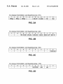
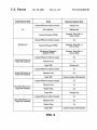
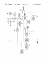
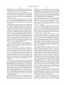
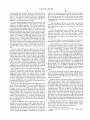
US006311282B1
(12) United States Patent
(10) Patent N0.:
Nelson et al.
(54)
US 6,311,282 B1
(45) Date of Patent:
*Oct. 30, 2001
METHOD AND APPARATUS FOR
COMPUTING DEVICE WITH STATUS
5,596,628 *
5,627,882 *
1/1997 Klein ............................... .. 379/93.11
5/1997 Chien et a1. ....................... .. 455/464
DISPLAY
5,629,715
5/1997
*
Zenda
.......
5,841,431 * 11/1998 Simmers
.
-
-
_
5,867,140
(75) Inventors‘ 53111115 IA)‘ptNO:lsgIX age“ B‘ Jaeger’
Notice:
345 98
Clara, CA (US)
Intel PentiumTM Processor User’s Manual, Volume 1: Pen
tiumTM Processor Data Book, Chapter 14, pp. 14—1 and
This patent issued on a continued pros-
14—2, 1993.
ecution application ?led under 37 CFR
*
1.53(d), and is subject to the tWenty year
patent term provisions of 35 U.S.C.
15 4(a)(2)'
cued by exammer
Primary Examiner_AyaZ R_ Sheikh
Assistant Examiner—Sumati LefkoWitZ
Subject to any disclaimer, the term of this
5314) Attorney’
.
.
_
_
Agent’
Or
Elrm—sklerven
acPherson LLP, Norman R. Khvans
U.S.C. 154(b) by 0 days.
(57)
(21) Appl' NO‘: 09/201,349
Filed:
Rader ......... ..
OTHER PUBLICATIONS
patent is extended or ad]usted under 35
(22)
2 1999
345/3
.. 345/211
5,881,299 * 3/1999 Nomura et a1. .................... .. 713/3/24
(73) Assignee: Fujitsu Personal Systems, Inc., Santa
(*)
*
. . . . ..
Mom“
ABSTRACT
A portable computing device' (e.'g. a notebook type
computer) also includes communications features including
Nov. 30, 1998
a pager receiver and a radio frequency modem Which are
supported by allowing the device, under application pro
Related US. Application Data
(51)
(52)
(58)
gram control, to resume operation from a suspend (sleep)
state upon receipt of a paging message. Additionally,
DlVlSlOIl Of application NO. 08/607,506,
On Feb. 27,
1996’ now abandoned‘
Int. c1.7 ...................................................... .. G06F 1/32
us. Cl. ......................... .. 713/324; 713/323; 345/212
Field of Search ................................... .. 713/320—324;
depending upon the Contents of [he
message, Various
application programs can be automatically launched in the
main processor Under application program Control, the
device can Operate in a background State With for instance
the main Screen’ its backhght and the keyboard powered
345/211, 212
doWn, but With the main processor running at full speed for
unattended operation. Under application program control in
normal or background mode, the device can request that the
unit suspend operation Without user intervention, for battery
poWer savings during unattended operations. Under appli
4656 318 *
5j041:964 *
4/1987 Noyes ........................... .. 379/10204
8/1991 Cole et a1_
_____ __ 713/322
Cation Program Control’ the device can Set the State of a
status message indicating a message pending or a urgent
570437721 *
8/1991 May _________ __
message Waiting. Thus reception of messages during unat
(56)
References Cited
U-S- PATENT DOCUMENTS
5,167,024 * 11/1992 Smith et a1,
5,189,632
5,337,044
574447869
574467904
*
*
*
*
:
5,530,879 *
5,537,650 *
2/1993
8/1994
8/1995
8/1995
Paajanen et a1.
Folger et a1
Stricklin et a1Belt 8t a1‘ "" "
340/825_44
713/322
tended and/or background state operation is communicated
..... .. 708/109
to the user Without resuming full operation. Additionally, in
-- 340/825-44
response to a drop in output voltage from the battery Which
~~~~~ " 455/575
is the system poWer supply, transmission poWer of the RF
713/323
modem is reduced, thereby alloWing RF modem transmis
glfelireitagl
sions over the entire battery discharge curve.
6/1996 Crump et a1. ..
713/323
7/1996 West et a1. ......................... .. 713/324
7 Claims, 6 Drawing Sheets
u_
I
Ll
14
-i
[FDD Pan]
a a ‘_r
55
KEG
Mist/hrs?“
MSABMM:
A
POWER SUPPLV umr/
POWER comm MPU
was
new Mammy
Mel
M Nzsmmm
‘so
U.S. Patent
0a. 30, 2001
CPU
Sheet 1 0f 6
10
14
/
/
P23S(33MHz)
16
A
Intel
Controller
X2
"
‘
A
cg??ol ;
WestemDigital~DSUb15 CRT
[
ll
System
Peripheral
Controller
WD7625LV
DRAM 4MB
(1 MX4b)
h
l
CARD
>
4/8/16MB
V
A
i A
A A
160450
160450 Power ATAj
PagerlF/SMI Tablet IF Manage
i A
"
/
2326
i
/ DRVA
6,0
we
_
i
A
68
i
/
D-5UB25Pin
72,
7s
4j
‘l /
7
CONNECTOR
A
A
ii
ll
-
68pin Header
70/[PCMC|A x 2]
[PCMClA ATA]
76
RAM Hadm
l
68pin Header
[Serial Port]
" /
A
/
D-SUBQpin Male
CONNECTOR
Cirrus Logic
But. \ 66
‘
i
CL-PD6720
Digital
1i
64
IR UNIT
A
ii
'
Pl(l>MlClLl\
Cont.| N56
; Western
52
>
4
4?
ll ll ll 4l8 3/8 5i0 <SER1> ii v v 5;
Super l/O
/ NOAH (AS'C) /
/ _ IDE> WD8120LV
<sER1>“\ e2 ‘LsERs>“<sEFi4>“
Female
rpara||e| pon]
26pm
[FDD Port]
Dt ‘
aa ‘
84
PAGEFl
88
/
96
/ ii
>
DRAM
pin
x8
\
82
JEIDA
88
WD811OLV
i
/lFl IF
58
34
/
;}22
A A
I
622:1:
‘
30
/
ir/
WesternDigital -*
l A
l
V A 28
A 26
llll/
System Cont.
WestemDigital
_
A
Marla
Serial MPX
1
>
A
Power
4i4
/
640x480
’
l’
ii
24
viiir/
Address:
20
A A A
A ‘lii
9e
LCD/
>
(256Kx16blv wo9oc24
A A A
Address<
18
/
VGA
VRAM
/P24S(50MHz)
US 6,311,282 B1
POWER SUPPLY UNIT/
POWER CONTROL MPU
FIG. 1
ii_
it
A
ii
ii
Flash Memo
Mitsubishi
lntel ry
M38802M2
N28F010-120
ll
94
ll
/
MiniDlN6pin Female [Keyboard]
V
U.S. Patent
0111. 30, 2001
US 6,311,282 B1
Sheet 2 0f 6
P011 Address FD61H/INDEX : 32H Head/Write [Initial : FFH]
7
6
5
4
3
2
RRQ2
RBQ1
RRQO
-
BG OP
8 DISK
1
H81
0
H80
FIG. 2A
Port Address FD61H/INDEX : 33H Read/Write [Initial : 00H]
7
6
5
4
3
2
-
-
BG ICON URG BL
URG ON
BOX B
1
0
BOX OUT BOX IN
FIG. 28
Port Address FD61H/INDEX : 34H Read/Write [Initial : FEH]
7
6
5
4
3
-
-
-
-
2
1
-
0
RADIOAK
FIG. 20
Port Address FD61H/INDEX : 2DH ReadNVrite [lnitiai : FFH]
7
6
5
-
4
3
2
1
O
ACPWR#
LLB#
LB#
-
FIG. 2D
U.S. Patent
lnitial System State
On
0a. 30, 2001
Sheet 3 0f 6
Event
Resulting System State
Suspend/Resume button pressed
Background
Auto suspend
Background
Suspend Request (PPMI)
Suspend/Resume button pressed
Background
Pager SMI enabled)
Pager SMI disabled)
Suspend, Ring Wait, or
Save-to-Disk
Pager SMI disabled)
Save_tO_DiSk
On
_
Resume Time
on
Pager SMI
Background
On
Resume Time
On
Pager SMI
Suspend (pager SMI rejected)
On
Resume Time
On
Modem Ring
On
Pager SMl
Background
Suspend/Resume button pressed
Ring Wait (Resume on
On
Background Operation
disabled (PPMI)
Suspend/Resume button pressed
Ring Wait (Resume on
Pager SMI enabled)
SaVe_tO_DiSk
Suspend, Ring Wait, or
Suspend/Resume button pressed
Suspend (Resume on
Suspend, Ring Wait, or
Suspend Request (PPMI)
Suspend/Resume button pressed
Suspend (Resume on
US 6,311,282 B1
.
On
Resume T'me
on
Modern Ring
On
Pager SMI
Suspend (pager SMI rejected)
FIG. 3
U.S. Patent
0a. 30, 2001
Sheet 4 of 6
US 6,311,282 B1
‘external subroutine for setting URGENT (ll!) display:
Const UBGENT_OFF = O
Const URGENT_ON = 1 Const URGENT_BL|NK = 2
Declare Sub SlC_Urgent Lib "c:\stat_lcd\iconctrl.dll"
(ByVal wStatus As Integer)
‘external subroutine for setting in/out box display:
Const DlBECTlON_OFF : 0
Const D|RECT|ON_|N = 1
Const DIBECT|ON_OUT = 2
Const DIBECTION_BOX : 4
Const DIRECTION__|N_BOX = 5
Const DIBECTION_OUT_BOX = 6
Const D|BECT|ON_|N_OUT_BOX = 7
‘OFF
lIN ARROW ONLY
‘OUT ARROW ONLY
‘BOX ONLY
‘IN + BOX
‘OUT +BOX
‘IN + OUT + BOX
Declare Sub SlC_Direction Lib “c:\stat_lcd\iconctrl.ddl"
(ByVal wStatus As Integer)
‘functions for MUXing serial port:
Declare Function GetMuxStat Lib "c:\stat_lcd\iconctrl.d|l"
( ) As Integer
Declare Sub SetMuxlFl Lib "c:\stat_lcd\iconctrl.dll" ()
Declare Sub SetMux9Pin Lib "c:\stat_lcd\iconctrl.dll" ( )
FIG. 4A
U.S. Patent
0a. 30, 2001
Sheet 5 0f 6
US 6,311,282 B1
Sub Form_Load ()
If GetMuxStat ( ) =1 Then
‘it UAFtT MUX is now InfraRed
MuxButt0n(1) .value = True
‘set IFt button to true
EIsde
|I;/IuxButton(O) .value = True
n
‘set 9-Pin button to true
InBox(0) .value = True
S|C_Direction (DIRECTION_OFF) ‘initialize in/out box to off
UrgStatus(O) .value = True
S|C_Urgent (URGENT_OFF)
‘initialize I ! I display off
End Sub
Sub |nBox_C|ick (Index As Integer)
If Index = 0 Then S|C_Direction (DIRECTION_OFF)
‘status icon off
It Index = 1
If Index = 2
If Index = 3
If Index = 4
If Index = 5
It Index = 6
‘in arrow on
‘out arrow on
‘box on
‘in + box on
‘out + box ()n
‘in + 0111+ box
Then
Then
Then
Then
Then
Then
S|C_Direction
S|C_Direction
S|C_Direction
S|C_Direction
S|C_Direction
S|C_Direction
(DIFIECTION_IN)
(DIRECTION_OUT)
(DIRECTION_BOX)
(DIRECTION_IN_BOX)
(DIRECTION_OUT_BOX)
(DIRECTION_IN_OUT_BOX)
End Sub
Sub MuxButton_CIiok (Index As Integer)
If Index = 0 Then
SetMux9Pin
End If
If Index=1 Then
SetMuxIR
End If
End Sub
‘Set the UAFtT to 9-Pin External
‘Set the UART to InfraFted
Sub UrgStatus_CIick (Index As Integer)
FIG. 48
If Index = 2 Then S|C_Urgent (URGENLBLINK)
If Index = 0 Then S|C_Urgent (URGENT_OFF)
If Index = 1 Then S|C_Urgent (URGENT_ON)
End Sub
FIG. 4C
‘blink urgent icon
‘urgent icon off
‘urgent icon on
US 6,311,282 B1
1
2
METHOD AND APPARATUS FOR
COMPUTING DEVICE WITH STATUS
DISPLAY
full operation. This standby state typically draWs more
poWer than does the suspend state.
Thus there is a continuum of exemplary computer states
involving increasing amounts of poWer consumption. The
?rst state is When the computer is actually off and draWing
This application is a division of application Ser. No.
08/607,506, ?led Feb. 27, 1996, noW abandoned.
no poWer (except perhaps for time purposes or to maintain
certain data in memory); the next state is the suspend state
BACKGROUND OF THE INVENTION
1. Field of the Invention
This invention relates to computers and especially to a
supported by the SMI; the next state is the standby state
10
operational.
portable battery poWered computer Which includes commu
nication features such as a Wireless modem and paging
receiver.
2. Description of the Prior Art
Portable computers are Well knoWn, as are personal
“communicators” of the type exempli?ed by the Motorola
Envoy. Such portable computing devices are invariably
battery poWered. Since presently available batteries have
very limited storage capabilities, it is important that such
Which corresponds to the instant on feature; and the last state
is the full on state in Which all computer subsystems are fully
HoWever neither the instant on feature nor the manually
15
generated SMI resulting in the suspend state are suitable for
a portable computer Which also includes communication
features. Such communication features, While generally not
part of portable computers, have been available in commu
nicators. These communicators typically have included only
modest computing capabilities but also include for instance
a conventional Wired modem for connection to telephone
20
portable computing devices (both computers and
lines, a Wireless modem for either facsimile, packet data,
and/or telephone communications, and a pager receiver (an
communicators) limit their poWer draW. Therefore there is
knoWn a Wide range of techniques for conserving poWer in
integrated pager).
such battery poWered devices. These poWer conservation
methods include shutting doWn portions (various
25
subsystems) of the computer When not in use, as Well as
putting the computer CPU (the main processor) to “sleep”
When its capabilities are not being used.
Since a purpose of such communicators is to be able to
receive messages from an external source at all times,
typically via the pager or the Wireless modem, the commu
nicator must be at least partly poWered up at all times. Thus
it is maintained in a loW poWer state (not off) even When the
user is not actively using it, in order to receive messages by
paging or radio modem transmission. This (relatively) loW
poWer state in fact requires a relatively high poWer drain
because signi?cant portions of the communicator must be on
Many portable computers have a main microprocessor of
the type commercially available from Intel and other sup
pliers called generically the “486 ” type. This microproces
sor (and some others such as the Intel PENTIUMTM
at all times in order to be able to receive the messages.
processors) includes a suspend/resume feature and system
management mode, for poWer management. Aspecial signal
Hence these communicators suffer from needing frequent
battery changes and/or recharges.
generated for instance by a set of key strokes or pushing a
special button on the computer or in some cases closing the
SUMMARY
top of the computer and thereby actuating a sWitch, is sent
to the microprocessor. This command is called the system
management interrupt (SMI) and is documented in the Intel
document Pentium Processor User’s Manual Vol. 1, 1993,
pp. 14-1 to 14-2. The microprocessor, upon receiving the
SMI When the microprocessor is operating, executes SMI
code in its SM (system management) mode, saves its current
register state of operation to SRAM memory, and then enters
a suspend (sleep) state in Which it is not quite off but draWs
In accordance With the present invention, several
improvements have been made in a combination portable
computer/communicator computing device Which in one
embodiment is a portable computer With an integrated
paging receiver and RF and/or Wired modem. These
40
improvements increase battery life by reducing current
drain, While enabling use of the communications feature at
all times. The paging receiver is operatively connected to or
integrated into the computing device itself so that a conven
very little poWer, and hence is for all practical purposes not
tional paging message can activate the computing device,
operating except for checking for a subsequent SMI.
for instance to alloW the radio modem to be turned on in
response to the paging message and to receive information
In response to subsequent receipt of an SMI, the micro
processor resumes operation (executes its RSM instruction)
With the same state that Was previously saved and does so
50
Which is then stored in the computing device. Thus the
computing device operates at all times as a full ?edged
very quickly. Hence the system management interrupt
communicator, Without excessive battery drain.
alloWs “toggling” betWeen the suspend and resume states,
In one embodiment the computing device is maintained in
a suspend state and upon receipt of the paging message, a
alloWing poWer conservation Without signi?cantly impeding
use of the computer, ie there is no need to reboot and reload 55
application programs.
In some computers the system management interrupt is
also generated by a timer; When for instance there has been
no keyboard input for a particular amount of time, the SMI
is generated, putting the computer into the suspend state
until additional keyboard activity occurs.
Another feature available in some portable computers is
the so called “instant on” feature. This is someWhat different
from the suspend state, in that the computer is maintained in
system management interrupt (SMI) is generated by the
pager interface and directed to the main microprocessor
(CPU) to resume operation of the CPU. This can also result
in turning on for instance of the radio modem to receive a
message. That is to say, depending upon the contents of the
60
paging message, various applications programs to be
executed by the CPU can be launched automatically. Thus
poWer management state of the computer is controlled
remotely by messages transmitted to the pager.
In another feature, under application program control the
a loW poWer standby state With some of the computer 65 computing device can set the state of a secondary status
subsystems, eg the screen, poWered doWn. Any of the usual
processor interrupts then bring the entire computer back to
display (typically a small auxiliary liquid crystal display
LCD) to provide an “urgent message Waiting” indicator.
US 6,311,282 B1
3
4
This takes place even though the computing device is
operating in a background state With the main display
poWered doWn. Thus the reception of messages for instance
cycles. This feature is implemented in one embodiment With
via the pager or radio modem during unattended and/or
background state operation can be visually indicated to the
to limit the range of received signal strength at the base
station receiver. This is an improvement over the prior art of
user, Without resuming full operation.
Thus, one operating mode of the computing device is the
adjusting the output poWer only after the minimum voltage
limit has already been reached. The present approach pro
longs battery usefulness for both rechargeable and non
no added circuitry since the packet radio protocol requires
that the output poWer be adjustable in discrete steps anyWay
background state, Which means that the CPU operates at full
clock speed for unattended operation. In order to reduce
poWer draW, various peripherals such as the main display
and keyboard are turned off (poWered doWn) in the back
ground state. With the computing device thus operating in
background state, upon receipt of for instance a paging
message by the paging receiver, the computing device can
automatically turn on its other peripherals, for instance the
rechargeable batteries.
1O
ing those With only limited computing capabilities.
BRIEF DESCRIPTION OF THE DRAWINGS
15
radio modem to receive data, Without user intervention.
In summary, this approach alloWs:
(1) The entire computing device to be suspended into a
very loW poWer consumption mode, except for the inte
to receive paging messages.
(2) Upon receipt of a message sent via a conventional
Wireless paging service, the computing device can be
(optionally) resumed by the integrated paging receiver to
FIG. 1 shoWs a block diagram of an exemplary portable
computing device in accordance With the present invention.
FIGS. 2A, 2B, 2C, and 2D shoW poWer control status
registers in accordance With one embodiment of the present
invention.
FIG. 3 shoWs system operating states in accordance With
grated paging receiver, Which remains poWered suf?ciently
full poWer-on operational state, that is it does not require
It is to be understood that the present improvements are
applicable to a range of portable computing devices, includ
the present invention.
25
rebooting the operating system nor reloading application
programs.
FIGS. 4A, 4B and 4C shoW a computer program for
control of a status display in accordance With the present
invention.
FIG. 5 shoWs a block diagram of a circuit for reducing
radio transmitter poWer output in response to a battery
supply voltage drop.
(3) Application programs can be launched to perform
various tasks, such as poWering on the RF modem and
invoking data transfer sessions, (optionally) depending on
DETAILED DESCRIPTION
the contents of the paging message received While the
FIG. 1 shoWs the block diagram of a computing device in
accordance With the present invention Which includes the
features and elements of a conventional “notebook” portable
computing device Was suspended.
(4) Additionally, there is a “background” poWer-on state,
Which operates With certain peripheral subsystems, for
example the display, pen and keyboard, poWered off, so:
35
computer combined With communications capabilities
including a pager receiver and a radio modem. This diagram
is exemplary (and not limiting) of a system in Which the
(a) the computing device can resume and operate unat
tended and the application program thus invoked can
re-suspend the computing device When it has com
present improvements may be incorporated. This particular
embodiment is a full functioned Intel 486 -type/DX2-50
notebook computer including a Mobitex radio frequency
pleted execution;
(b) the unattended operation of the computing device Will
modem and a POCSAG-paging receiver. With reference to
not be interrupted by unintentional user intervention
e.g. the pen or keyboard;
FIG. 1, the CPU 10 (main microprocessor) is an Intel-type
(c) poWer consumption is minimiZed during unattended
operation, because several of the subsystems are poW
ered doWn.
486 processor, e.g. the P23S or the P24S. CPU 10 is
connected to a conventional address, data and control bus 22
45 to Which is also connected a video memory (VRAM) 14 via
conventional VGA controller 16, e.g. a WD90C24 Western
Digital. Connected to VGA controller 16 is the LCD Which
(5) Further, a separate LCD status display is poWered up
even While the computing device is suspended for notifying
is the main computer display having the pixel dimensions as
shoWn, and the secondary display 20 connected by a D15
connector. There is also provision (not shoWn) for connec
the user both of the current poWer management state of the
computing device, including “background” mode, and of
tion of a cathode ray tube-CRT.
Also connected to the bus 22 is a conventional system
conditions determined by an application program, such as an
urgent message has been received.
In another feature, a poWer control circuit is provided for
peripheral controller 24 e.g. the Western Digital
WD7625LV, a system controller 26 e.g. the Western Digital
the transmitter portion of the radio (Wireless) modem in
order to maintain, over the entire discharge curve of the
55
memory card 34 including additional random access
memory.
Connected to the portion 22A of bus 22 is an interface and
poWer management integrated circuit 38 Which in this case
is an ASIC (applications speci?c integrated circuit, ie a gate
array) Which includes various functions. The ?rst function is
based on a knoWn relationship betWeen poWer ampli?er
input voltage, input current and output poWer level. The
output poWer level is then set so that the input voltage Will
never be less than the required minimum level. This alloWs
successful radio modem transmissions throughout the dis
charge curve of the battery, to compensate for the battery
voltage drop as is typical of batteries during their discharge
WD8110LV, 4 megabytes of dynamic RAM 28, and
(connected via 88 pin connector 30) a JEIDA DRAM
battery, a minimum required level of input voltage to the
radio transmitter poWer ampli?er. This poWer control circuit
measures the battery voltage prior to the start of transmis
sion and predicts What the input voltage to the poWer
ampli?er Will be When transmission starts. This prediction is
a multiplexed serial port/IR interface 44 Which connects via
65
a 232C driver circuit 58 to a 9 pin connector 60 for
connection to a serial port device. Port 44 also connects to
an infrared unit 62 Which provides infrared serial commu
nications. Thus there are tWo 16C550 UARTS in the Western
US 6,311,282 B1
5
6
Digital WD8120LV chip 54; UART 44 is multiplexed by
APM utiliZes more complete cooperation betWeen the oper
ASIC 38 between 9 pin connector 60 and an IR unit 62. The
other UART is connected to (RF) modem 82.
The next element is the pager interface 46 Which is an
(PPMI) interface, for example, sending “Warning” messages
ating system, application programs and the BIOS APM
to application programs before alloWing the system to
connected to a tablet unit 64. This is for a conventional
suspend (eg after a period of inactivity). Microsoft has
extended this concept to their WindoWs Operating System
message servicing architecture by providing WindoWs APM
pen-based input. The tablet unit 64 is located physically
drivers (POWER.DRV and VPOWERD.386).
16C450 interface connectable via connector 78 to a pager
84. Also provided is the 16C450 tablet interface 48 Which is
under the screen 18.
ApoWer management function portion 50 is described in
10
greater detail beloW. ATAportion 52 connects via a buffer 66
In accordance With the present invention, the Phoenix
PPMI is extended, adding services to enable/disable Back
ground Mode and the ability for an application program to
to a connector 68 for PCMCIA ATA, Which is a hard disk
request that the system suspend (Suspend is usually
drive interface similar to the IDE interface (Integrated Drive
requested by the BIOS). To alloW applications to access
Electronics).
Also connected to the ASIC 38 is a super I/O chip 54 eg
the WD8120LV, Which also connects to the bus 22A. The
next element is a PCMCIA controller 56 Which is eg the
Cirrus Logic CL-PD6720 connecting also to bus 22A and
connecting to PCMCIA cards (e.g. tWo such cards) via a
connector 70. Also shoWn are connectors 72 and 74 con
these extensions in the MS-WindoW environment, a Win
15
doWs driver is provided.
A feature of APM is that, except in the case of a loW-loW
battery “crisis” suspend, device drivers and application
programs are noti?ed of a suspend request and may reject if
20
necting to respectively a parallel port and ?oppy disk drive
port of the super I/O 54 chip. In the loWer left hand portion
they are busy. If some applications accept the suspend
request and others reject it, this may lead to synchroniZation
problems since the system has not suspended, but some
drivers or applications may think they Were suspended, since
of FIG. 1, connector 76 connects the super I/O chip 54 to the
they did not reject the suspend request.
radio (and also Wired) modem 82. RF modem 82 may be for
In a ?rst feature in accordance With the present invention,
operation of this computing device is alloWed to resume
from a suspend state upon receipt of a paging message. That
is, under program control, the computing device resumes
operation of the main processor 10 from a suspend state
upon receipt of a paging message Which has been transmit
instance a cellular telephone modem or other type of Well
knoWn radio-based modem such as MOBITEX, ARDIS or
CDPD, etc. PoWer supply unit and poWer supply microcon
troller unit 96 include the actual poWer supply and the
associated microcontroller Which are connected (for control
purposes) to the poWer management portion 50 of the ASIC
38 and to system peripheral controller 24.
In the loWer right hand portion of FIG. 1 is a Data bus to
Which is connected the keyboard controller 88 Which is
ted to pager 84. This program is the resume code in the
BIOS, Which is executed in SMM after receipt by main
processor 10 of the SMI. Additionally, depending upon the
contents of the paging message, additional application pro
connected to a keyboard 94 via a connector 94 and also a 35 grams can be automatically launched by main processor 10
Without user intervention.
BIOS (basic input output system) ?ash memory 90 for
system memory purposes.
This feature is supported in the BIOS (eg the commer
cially available Phoenix Technologies BIOS referred to
above) stored in memory 90 as folloWs. A parameter is
While in this case the RF modem 82 is a Mobitex type
modem, this is not limiting but is illustrative. Similarly in
this case the pager 84 is a POCSAG type paging receiver
Which provides alphanumeric information of a type more
extensive than a mere telephone number. This is Well knoWn
and of a commercially available type and again is not
limiting but is illustrative. It is to be understood that each of
the various elements shoWn in FIG. 1 is of commercially
available type except as described hereinafter. Moreover, the
40
45
puting devices; the device of FIG. 1 is illustrative of one
application.
50
MENT BIOS Interface Speci?cation Rev. 1.1, SEP-93, Intel
MS-DOS Operating System a poWer management device
driver, POWEREXE, Which (optionally) uses the BIOS
minimiZing poWer consumption but alloWing quick resump
Thus With reference to FIG. 1, a paging message is conven
tionally transmitted from an external source to the pager 84.
This paging message is then sent via the pager interface 46
to the ASIC 44, and then the ASIC 44 generates an SMI
Which is sent to the main processor 10 Which in response
puts the computing device into the background state,
Part Number 241704-001). These interfaces include a BIOS
interface, Which has been implemented With extensions by
Phoenix Technologies in their BIOS (Basic Input/Output
System) product as the Phoenix PoWer Management Inter
face (PPMI). Additionally, Microsoft provides With its
described above, Wherein the main processor 10 effectively
suspends execution but saves its previous state thereby
tion of full operation. This is a Well knoWn feature of the 486
type of microprocessors and is not described further herein.
features described hereinafter are applicable to other com
As a matter of technical background, APM (Advanced
PoWer Management) is a general set of interfaces de?ned by
Microsoft and Intel (see ADVANCED POWER MANAGE
provided in the BIOS Which either enables or disables the
“resume on pager” feature. When this feature is enabled, the
processor 10 resumes operation from the suspend state if a
paging message is received. This suspend state is as
55
Whereby the main processor 10 operates at its full clock
speed but the other peripherals (such as the display 18 and
keyboard 88) are not poWered up.
Note that in the background state, the auto suspend feature
60
of main processor 10 is not operative. Therefore an appli
cation program running on main processor 10 in the back
ground state must suspend operation of the main processor
services to alloW MS-DOS and the end user limited control
of system’s poWer management mode; the modes being Off,
10 using a suspend request as described beloW to avoid the
Standard & Advanced.
synchroniZation problems alluded to above.
It is therefore possible for the PCMCIA cards (attached
Standard PM (PoWer Management) mode does not rely on
BIOS services and has very limited functionality (i.e.
MS-DOS can put the processor into a loWer poWer mode, if
the operating system and application softWare are “idling”).
65
for instance to connector 70) to be off While the main
processor 10 remains operating. This is because APM-aWare
application programs can accept or reject the suspend
US 6,311,282 B1
7
8
request noti?cation, but other application programs, such as
and may try suspend system operation during communica
the PCMCIA card manager, may not be aWare of such
tions. HoWever the BIOS does not alloW the main processor
10 to enter the suspend state until a particular communica
rejection. Once the main processor 10 is in its background
state, i.e. operating at normal clock speed, any desired
application program can be automatically launched in
response to a particular paging message.
tion is completed and the communication module is idle.
Background state is the same as the fully on state, With the
exceptions that:
Thus the paging message may resume execution of an
1. The main display 18 and its associated back light (not
application program(s) by the main processor upon the
receipt of the paging message. The resumed application
program(s) are those Which Were active at the time of the
previously executed suspend request. The contents of the
paging message may be scanned (by one of the reactivated
application programs after operation of the main processor
has been resumed) and depending on the message contents,
another application program(s) launched Without user inter
10
suspended.
2. The auto-suspend feature is disabled because some
application programs may require more time than the auto
15
vention. For instance a particular paging message may
any activity).
3. The tablet 64 (and its associated pen) and the keyboard
68 input are ignored to prevent accidental user input.
Certain operations are prohibited in the background state.
An application program must not disable poWer manage
ring.
25
in the BIOS, Which in turn restores the state of the comput
ing device to What it Was at the instant before the suspend
request SMI Was generated. Control is then returned to the
operating system, eg a combination of MS-DOS and Win
doWs. WindoWs’ COMM driver Will service a pending
ment While the computing device is in the background state.
If poWer management is disabled While the computing
device is in the background state, the computing device
cannot be returned to the on state by pressing the suspend/
resume button or by executing keystrokes. An application
program running in the background state must not issue a
suspend request through the APM driver. Instead the appli
cation program must use the BIOS PPMI suspend request, as
described beloW. An application program running in the
background state must not change the auto suspend timer
regular (not system management) interrupt from the paging
receiver and retrieve the received paging message, Which is
then passed onto a paging application program. This paging
application program can invoke another application program
suspend timer alloWs. (The auto suspend timer normally
puts the computing device into the suspend state if a
particular time, as measured by the timer, elapses Without
indicate to turn on the RF modem 82 for receipt of a longer
message Which is automatically doWnloaded into the com
puting device from a remote source via the RF modem 82.
This occurs Without user intervention, and generally Without
the user even being aWare of this happening. For instance,
the computing device could be in the user’s briefcase or
otherWise left unattended While these operations are occur
Thus the System Management Interrupt causes the main
processor to return to “full” (normal operation) processing
speed and execute special system management resume code
shoWn) are turned off, both to conserve poWer and to make
the computing device appear to the user as if its operation is
35
depending on the contents of the paging message.
Upon completion and receipt of the message, for instance
via the RF modem 82, i.e. completion of execution of the
through the PPMI or SETUP modules. An application pro
gram running in the background state must not change the
display timeout through PPMI or SETUP. Once the back
ground state operation has been enabled, it stays enabled
until explicitly disabled or until a PPMI suspend request is
issued.
application program, the main processor 10 returns to the
Thus in the background state the computing device can,
suspend state upon receipt of a suspend request from the
under application program control, operate With the display
18, its associated backlight, and the keyboard 88 off, but
application program. When the suspend request is issued,
the BIOS immediately initiates the suspend procedure. This
request is valid When the computing device is in the on state
or in the background state, as described beloW. Even if
With the main processor 10 running at full clock speed for
45
unattended operation.
Another feature in accordance With the present invention
background state operation is enabled, the computing device
goes into the suspend procedure.
supports the background state and unattended operation of
the computing device. That is, the computing device can,
Note hoWever that the computing device does not neces
under application program control, set the state of the status
sarily actually suspend operation if an APM (softWare)
LCD 20 (a small LCD independent of the main screen 18)
driver is connected. Rather, a suspend request noti?cation
message is sent to all APM-aWare drivers (softWare
modules) and to application programs Which may reject the
suspend request if they are busy and do not Want to suspend
Waiting indicator. Thus the reception of messages during
unattended and/or background state operation is communi
operation. Thus, after completion of the desired task, the
computing device, under control of the application program,
to provide a message in/out icon and an urgent message
55
returns to the suspend state, i.e. is asleep, aWaiting the next
need to resume operation. The actual return to the suspend
state is performed by the BIOS and the suspend feature of
the main processor.
Thus the availability of the background state operation
supports the resume-on pager feature. Again, this feature is
enabled or disabled depending on a BIOS parameter. The
computing device is intended to send and receive various
cated to the user Without resuming operation of the com
puting device. This is because the status LCD 20 is in
operation even When the main processor 10 is in the suspend
state. That is to say, this information displayed by the LCD
20 is provided from the poWer management microccontrol
ler 96 and ASIC 44 rather than from the main processor 10.
FIGS. 2A, 2B, 2C and 2D shoW various located registers
in ASIC 44 to support the above described poWer control
features. FIG. 2A shoWs a host command/status register
Where the bits have the folloWing signi?cance:
data Without user intervention as described above. Thus it is 65
possible that the user may not even notice that the commu
Bit 7—5: RRQZ-O (Radio Request)
nication module (pager 84/RF modem 82) is in operation,
module).
Request code for poWer source of RF modem (radio
US 6,311,282 B1
10
-continued
RRQ 2-0 Request
Bit 2: LLB# (Low Low Battery)
[0, 0, 0]: Reset of acknowledge
[1, 1, 0]—[1, 1, 1]: Reserved
[0, 0, 1]: Reserved
This bit shows the status of the main battery of the
computing device.
0: Low low battery (need to stop operation)
[0, 1, 0]: Power source for COM. Module ON
1: none
[0, 1, 1]: Reserved
[1, 0, 0]: Reserved
Bit 1: LB# (Low Battery)
This bit also shows the status ot main battery.
[1, 0, 1]: Power source for COM. Module OFF
Bit 3: BGiOP (Back Ground Operation)
0: Low battery (need to pay attention)
10
This bit informs of the background state to Power
MPU96. Whenever the computing device enters into
the background state, this bit is set.
FIG. 3 shows (in a tabular form) a state diagram indicat
ing state transitions where the background state operation is
0: Background Mode Disabled 1: Background Mode
Enabled
Bit 2: SiDISK (Save to Disk Mode)
This bit informs of the setting of system set-up
15
menu to Power MPU 96. Change of the system
setting is re?ected in this bit.
0: Save to Disk 1: Memory Suspend
“Background”, “Waiting” or “Suspend”.
up) state, (2) the background operation state, (3) the susp end
20
state, and (4) the ring wait state. The state transitions are
determined by the BIOS. While the corresponding BIOS
code is not shown here, it is readily written by one of
ordinary skill in the art in light of this disclosure.
Every change of the state is re?ected in this
bit.
[HS1, 0] = [0, 0] Suspend
[0, 1]: RI Waiting
As described above, one feature which supports the
[1, 0]: Background operation
[1, 1]; ON
enabled. The “Suspend/Resume button” is a user-controlled
button on the computing device allowing the user to toggle
between these two states. “Ring Wait” is the state of await
ing a Modern Ring. This state diagram makes clear the
transitions between the states of (1) being on (fully powered
Bit 1-0: HSI-0 (Host Status)
These bits inform of the system state, eg “ON”,
1: none
25
background and suspend states is the provision of the
message in/out and the urgent message waiting via the status
display 20. The corresponding urgent status icon can have
The icon display register controls the urgent message
any one of three values, i.e. off, on, or blink. The in/out
feature and as shown in FIG. 2B has bits having the
message box status i con can have any one of the values off,
following signi?cance:
30
in arrow only on, out arrow only on, message box only on,
in arrow in box on, out arrow in box on, and in and out and
in box on. Thus the status display 20 shows these icons even
when the computing device itself is in the suspended state.
Hence, an application program running in the background
Bit 5: BG ICON (Background Operation Icon)
This bit turns on or off the icon on status display
20 indicating “Background operation”.
state can warn the user of an urgent message by using the
35
0; ICON oFF 1; ICON ON (Display)
status display in response for instance to a received paging
message which wakes the computer from the suspended
state and puts it in the background state. The urgent message
Bit 4-5: URGiXX (Urgent Icon)
This bit controls the icon of “URGENT”.
Bit 4: URGiBL (Urgent Icon blink)
icon can ?ash on and off to better attract attention of the user.
0: No blink 1: Blink
This indicates a received paging message for instance or
Bit 3: URGiON (Urgent Icon ON/OFF)
0: ICON OFF 1: ICON ON
40
This bit controls the icon of “IN/OUT BOX”.
Bit 2: BOXiB (“BOX” Icon of IN/OUT BOX ON/OFF)
0; ICON oFF 1; ICON ON (Display)
Bit 1: BOXiOUT (“OUT” Icon of IN/OUT BOX ON/OFF)
0; ICON oFF 1; ICON ON (Display)
initial receipt of a paging message followed by, after the RF
modem is turned on, a longer message received via the RF
modem. Thus an application program running in the back
ground state may turn on the urgent message icon to indicate
Bit 2-0: BOXiXX (IN/OUT BOX Icon)
45
Bit 0: BOXiIN (“IN” Icon of IN/OUT BOX ON/OFF)
0; ICON oFF 1; ICON ON (Display)
receipt of an urgent message and then again suspend opera
tion of the computing device while the urgent message icon
continues to be displayed and/or to ?ash. That is to say, this
status display 20 continues to provide an indicator even in
the suspend state of the computing device. This status
display 20 is eg a re?ective (not backlit) LCD to minimize
The power MPU acknowledge register of FIG. 2C con
trols the power source switching for the radio modem 82 and
has the single bit as follows:
power drain so that it at least a portion of it is powered on
response against “Radio RQ”. 0: none (or Nack) 1: Power
source switching completed.
at all times while drawing minimum power.
FIGS. 4A, 4B and 4C show a exemplary (application)
computer program for controlling the urgent message indi
cator icon. FIG. 4A shows this program’s general declara
tions and FIGS. 4B and 4C show the actual program. The
software module ICON CTRL.DLL receives passed param
eters as Word values. Because the language in which this
The power MPU status register of FIG. 2D has the
meaning as follows:
program is written, Visual Basic, passes parameters by
reference, the “ByVal”, keyword is required in the declara
Bit 0: RADIOAK (Radio Acknowledge)
When the power source switching requested by “Radio
RQ” is completed, this bit becomes “1”. Nack (negative
acknowledge) is informed by more than 500 ms of no
55
60
tion in FIG. 4B to pass the correct parameters. Similarly, the
value “As Integer” ensures that the value passed is a 16 bit
(Word) value.
Bit 3: ACPWR (AC Power Source)
Upon loading this program, both status display support
This bit shows the status of external power source
services are initialized to Off, to avoid synchronization
input.
0: External power source inputting
1: No external power source input
65
problems. The current assignment of the UART 84 is
determined, and the appropriate option button set to true to
display that assignment.
US 6,311,282 B1
11
12
Another feature in accordance With the present invention,
as described above, is control of the output poWer of the RF
modem 82 in response to diminished battery voltage. A
block diagram of a circuit to accomplish this is shoWn in
Battery
Charge Lvl.
Battery
Voltage
Power
Output
Power Amp
Input Volt
PoWer Amp
Current
Full
90%
75%
60%
45%
30%
15%
0%
7.4 Volts
7.25
7.0
6.75
6.35
6.0
5.85
5.7
3.0 Watts
3.0
2.9
2.5
2.1
1.7
1.4
1.2
7.0 Volts
6.8
6.55
6.1
5.7
5.4
5.4
5.4
1 5 Amps
1.6
1.7
1.8
1.9
1.8
1.4
1.2
FIG. 5.
The circuit of FIG. 5 shoWs relevant portions of RF
modem 82; the remaining portions are conventional. The
data from super I/O chip 54 to be transmitted is coupled to
poWer ampli?er 102, Which in turn has its output terminal
10
coupled to radio antenna 104. Battery 106 (the battery of the
device shoWn in FIG. 1) has a conventional variable output
battery voltage, and is coupled through circuit resistance 108
to supply drive current to poWer ampli?er 102, thereby
providing a poWer ampli?er input voltage Which is measured
and converted by analog to digital converter 110, the digital
15
are intended to fall Within the scope of the appended claims.
Also, it is to be understood that the various features
output terminal of Which is connected to an input terminal of
microccontroller 112 (This microccontroller is part of block
82 of FIG. 1.).
Microcontroller 112 provides a (digital) poWer out level
reference value Which is converted to an analog signal by
digital to analog converter 116 to drive the positive terminal
of error ampli?er 120, the inverting terminal of Which is
connected by a feedback loop to the antenna104 by poWer
measuring circuit 124. Error ampli?er 120 provides a poWer
level setting to the control (gain) terminal of poWer ampli?er
102.
It is characteristic of the poWer ampli?er 102 used in this
described herein may in at least some cases be independent
20
operating the computing device in a suspend state Wherein
30
decreases, the poWer ampli?er current increases, in an
attempt to maintain a constant PoWer Out as established by
battery 106 discharges during transmitter operation. Since
40
maintains the required minimum poWer ampli?er input
voltage by adjusting the poWer ampli?er poWer level setting.
full discharge cycle of the battery 108, although at reduced
45
poWer ampli?er input voltage is equal to the battery voltage.
When the poWer ampli?er 102 is transmitting, hoWever, the
poWer ampli?er input voltage is loWer than the battery
voltage due to the voltage drop across the circuit resistance
108. The microccontroller 112 samples the input voltage
before the poWer ampli?er 102 begins transmitting and then
50
requires that the transmitter poWer be adjusted in any case to
compensate for changes in receiver signal strength. Exem
plary poWer level settings controlled by a conventional
program resident in microccontroller 112 are shoWn in the
folloWing table:
display Which is a liquid crystal display coupled to the main
processor, and further comprising:
means for operating the computing device in a suspend
state Wherein the poWer management circuit and at
least a portion of the status display are poWered up, and
the main processor and the main display are off;
puting device from an external source; and
means for poWering up the main processor in response to
55
across the circuit resistance 108 caused by the poWer ampli
?er current Will provide not less than the minimum required
eg 5.4 volts input voltage to the poWer ampli?er 102.
The advantage of this approach is that compensation for
variations in battery voltage is accomplished Without adding
additional circuitry, since the packet radio netWork protocol
at the computing device, after the step of resuming the
normal operation of the main processor.
2. The method of claim 1, further comprising the step of
not poWering up the main display When the main processor
means for receiving a message transmitted to the com
adjusts the poWer out level reference to a value Which
ensures that the battery voltage minus the voltage drop
response to receipt of the message; and
indicating on the status display a reception of the message
resumes normal operation.
3. A computing device having a main processor, and a
poWer management circuit, a main display and a status
This alloWs operation of the poWer ampli?er 102 over the
output poWer levels.
When the poWer ampli?er 102 is not transmitting, then the
the poWer management circuit and at least a portion of
the status display are poWered up, and the main pro
cessor and main display are off;
transmitting a message to the computing device from an
eXternal source;
resuming normal operation of the main processor in
35
voltage of eg 5.4 volts, so it is necessary to ensure that this
minimum input voltage is exceeded or maintained as the
the relationship betWeen poWer ampli?er current and PoWer
Out is knoWn and predictable, the circuit shoWn in FIG. 5
of one another, and it is contemplated that a computing
device may include only some of these features.
We claim:
1. A method of operating a computing device having a
main processor, a poWer management circuit, a main display
and a status display Which is a liquid crystal display,
comprising the steps of:
computing device that, as the poWer ampli?er input voltage
the “PoWer Level Setting” input to the poWer ampli?er 102.
The poWer ampli?er 102 Will not operate properly beloW a
This disclosure is illustrative and not limiting; further
modi?cations Will be apparent in light of this disclosure and
receipt of the message, and after the main processor is
poWered up, indicating on the status display a reception
of the message at the computing device.
4. The computing device of claim 3, further comprising
means for not poWering up the main display When the main
60
processor is poWered up.
5. A method of operating a computing device having a
main processor, a poWer management circuit, a main display
and a status display, comprising:
operating the computing device in a suspend state Wherein
the poWer management circuit and at least a portion of
the status display are poWered up, and the main pro
cessor and main display are off;
US 6,311,282 B1
14
13
means for operating the computing device in a suspend
state Wherein the poWer management circuit and at
least a portion of the status display are poWered, and the
main processor and the main display are off;
transmitting a message to the computing device from an
external source;
resuming normal operation of the main processor in
response to receipt of the message;
indicating on the status display a reception of the message
at the computing device, after the step of resuming the
normal operation of the main processor; and
continuing to display a message Waiting indicator during
the suspend state of the computing device.
6. The method of claim 5, furthercomprising not poWering
means for receiving a message transmitted to the com
puting device from an external source;
means for poWering up the main processor in response to
10
up the main display When the main processor resumes
normal operation from the suspend state.
7. A computing device having a main processor, and a
poWer management circuit, a main display and a status
display coupled to the main processor, and further compris
mg:
15
receipt of the message, and after the main processor is
poWered up, indicating on the status display a reception
of the message at the computing device; and
Wherein a message Waiting indicator is displayed during
the suspend state of the computing device.


![[54] W, rm-pg`vzvlsggéggllslswnolq MONITOR OTHER](http://vs1.manualzilla.com/store/data/005697201_1-5cf72edac23b396dc325f3c508f97781-150x150.png)