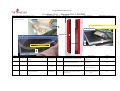
1
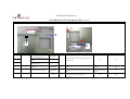
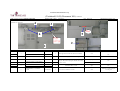
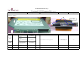
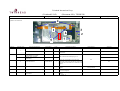
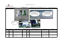
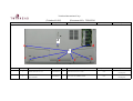
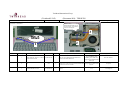
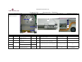
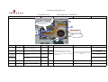
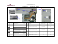
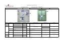
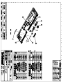
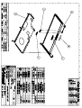
Table of Contents
efio!121i BOM……………………………………………………………….
1
efio!121i 12.1" LCD SOP……………...……………….……………………..
8
efio!121i Additional Operations Instruction Manual……...…………………..
20
efio!121i System Setup Instruction Manual…………………………………...
33
efio!121i (Complete set) Instruction Manual…………………………………
53
efio!121i Disassembly………………………………………………………..
62
efio!121i Notebook BOM
(internal code name: E12B)
======= =============
================================== ===========
Level
P/N
Description
Unit
======= =============
================================== ===========
#8019 BASE MODULE-W/GENERIC BIOS
PCE
1
.....5
82-814700-00
E12B-PCB ASS'Y-GM-PM-REV:0-W/BIO
PCE
1
....4
80-878000-00D
E12T-PCB ASS'Y-KN-DC-IN-REV:D-W/
PCE
1
....4
80-878100-00A
E12T-PCB ASS'Y-KN-USB-REV:A-W/ME
PCE
1
....4
.....5
.....5
.....5
.....5
.....5
.....5
.....5
.....5
.....5
.....5
.....5
.....5
.....5
.....5
.....5
.....5
.....5
.....5
.....5
86-643000-00
22-600043-10
29-001734-00
29-001735-00
29-015340-00
40-003553-01
40-008163-00
40-008180-00
40-011662-00
41-721520-03
41-721526-05
41-850520-06
50-035190-00
50-035191-00
50-035192-00
50-964101-01
50-964301-01
51-035041-00
51-036212-00
51-350094-01
#8019/#8131 SYSTEM CABINET-E12B
PCE
PIFA ANTENNA-W/HARNESS-FOR GEMTE PCE
E12T-MDC MODEN HARNESS-SH7340
PCE
E12T-POWER HARNESS-SH735
PCE
P22AJ-SB-USB FPC-CA340A
PCE
E12B-HEATSINK MODULE-W/FAN-W/THE PCE
E12T-AL FOIL FOR K/B BRACKET EMI
PCE
E12B-UPPER AL FOIL-E4838A
PCE
E12T-RAM DOOR-#8019-C3778A
PCE
SCREW ISOT-M2X3L-SELF-LOCKING ¡í
PCE
SCREW ISOT-M2.6X5L H=0.8mm-NYLOK PCE
SCREW ISOP-M2X6L-SELF-LOCKING-B3 PCE
E12T-HINGE COVER-L-#8019-E46790
PCE
E12T-HINGE COVER-R-#8019-E46800
PCE
E12T-HARNESS COVER-#8019-E46810
PCE
E12T-CPU DOOR ASS'Y-#8019-E1097PCE
E12B-UPPER COVER ASS'Y-#8019/#81
PCE
ELECTRICALLY CONDUCTIVE-FABRIC T PCE
E12T-SPONGE FOR POWER BUTTON-E48 PCE
CONDUCTIVE SPONGE 5X2X1000mm-KL1 PCE
1
1
1
1
1
1
1
1
1
9
2
14
1
1
1
1
1
1
1
0.12
efio!121i Notebook BOM
(internal code name: E12B)
======= =============
Level
P/N
======= =============
.....5
51-350094-02
.....5
51-350094-03
.....5
51-350094-05
.....5
51-350094-06
.....5
51-350094-15
.....5
51-350094-21
.....5
51-350094-23
.....5
52-000000-20
.....5
52-002022-20
.....5
52-002121-00
.....5
63-250190-00
.....5
76-060007-00
.....5
77-643007-00
......6
40-002470-00
......6
40-006040-00
......6
40-011951-00
......6
41-420520-03
......6
50-023107-10
......6
50-043080-01
......6
51-036041-10
......6
51-036042-10
......6
51-350094-02
......6
51-350094-06
......6
51-350094-15
......6
52-000000-20
.....5
77-643009-00
......6
22-300000-00
================================== ===========
Description
Unit
================================== ===========
CONDUCTIVE SPONGE 5X3.5X1000mm-K PCE 0.015
CONDUCTIVE SPONGE 5X5.5X1000mm-K PCE 0.035
CONDUCTIVE SPONGE 9X3.5X1000mm-K PCE 0.02
CONDUCTIVE SPONGE 10X1X1000mm-KL PCE 0.03
P88S-CONDUCTIVE SPONGE 10X0.5X10 PCE 0.035
CONDUCTIVE SPONGE-7X1X1000mm-KL1 PCE 0.045
E12T-CONDUCTIVE SPONGE-3X4X1000m PCE 0.025
P22AJ-RUBBER FOOT-PANTONE 428C-D PCE
2
P22AJ-LOWER CD-ROM RUBBER-PANTONPCE
1
E12T-RUBBER FOR HDD-E4803A
PCE
1
KEY PARTS BARCODE LABEL-KL18260
PCE
1
1
MDC MODEM CARD-SMART LINK-MDC56SPCE
E12B-#8019 M LOWER COVER KIT
PCE
1
E12B-LOWER COVER-#8019-B1328
PCE
1
N222S1-BATTERY HOOK-B3377A
PCE
1
N222S1-BATTERY LATCH SPRING-D479 PCE
1
SCREW BPS/W (¡í5.5)-M2X3L-NYLOKPCE
2
E12T-DC INDICATOR-PANTONE 428C-D PCE
1
E12T-BATTERY LATCH-#8019-E4705A
PCE
1
E12T-HDD SPONGE FOR LOWER UP SID PCE
1
E12T-HDD SPONGE FOR LOWER DOWN SPCE
1
CONDUCTIVE SPONGE 5X3.5X1000mm-K PCE 0.025
CONDUCTIVE SPONGE 10X1X1000mm-KL PCE 0.025
P88S-CONDUCTIVE SPONGE 10X0.5X10 PCE 0.03
P22AJ-RUBBER FOOT-PANTONE 428C-D PCE
2
E12B-#8019/#8131 PALM REST KIT
PCE
1
PCE
1
SPEAKER (R)(L)-W/RUBBER-C3781
efio!121i Notebook BOM
(internal code name: E12B)
======= =============
Level
P/N
======= =============
......6
29-016338-00
......6
40-008051-00
......6
40-008181-00
......6
40-030884-00
......6
40-030885-01
......6
41-760020-02
......6
50-964301-11
......6
51-005060-00
......6
51-350094-02
......6
73-080052-20
================================== ===========
Description
Unit
================================== ===========
P22AJ-FFC (P=1.0) FOR TOUCHPAD-C
PCE
1
P14N-UPPER EMI AL FOIL-E41290
PCE
1
E12B-AL FOIL FOR PALMREST-IN SPE
PCE
1
E12T-BRACKET FOR PALMREST SPEAKE PCE
2
E12T-TOUCHPAD BRACKET-C3776A
PCE
1
SCREW ISOTT-M2.0X2L ¡íD3.4/H0.4m
PCE
2
E12B-PALM REST ASS'Y-#8019/#8131
PCE
1
E12T-SPEAKER MESH-BLACK-E46930
PCE
2
CONDUCTIVE SPONGE 5X3.5X1000mm-K PCE 0.015
TOUCH PAD-SOTEC P-03012-SYNAPTIC PCE
1
BAT
...3
23-050180-10
BAT-LIION-3S2P-2200mAh-#8019-PS-
PCE
1
CPU
...3
...3
...3
...3
...3
...3
...3
52-003091-00
76-070021-10
01-007590-G0
01-0076E1-G0
01-0076J4-G0
01-0076J2-G0
01-0076J3-G0
P22T-RUBBER FOR WIRELESS-E45500
WLAN MODULE MINIPCI-3.3V-TYPE 3B
CPU-PENTIUM M CELERON-1.3GHZ-uFC
CPU-BANIAS PGA-1.4GHZ/600MHZ-UFC
CPU-BANIAS PGA-1.7GHZ/600MHZ-uFC
CPU-BANIAS PGA-1.5GHZ/600MHZ-uFC
CPU-BANIAS PGA-1.6GHZ/600MHZ-uFC
PCE
PCE
PCE
PCE
PCE
PCE
PCE
1
1
1
1
1
1
1
HDD
...3
....4
....4
....4
...3
77-606008-20
40-008140-00
40-030691-01
41-870130-04
70-922400-50
N222S1-HDD KIT
D212A-AL FOIL FOR HDD BRACKET-E4
N222S1-HDD BRACKET-C3421B
SCREW ISOF-M3X4L-B3519L
HDD-40GB-2.5"-9.5X100X70mm-MHT20
PCE
PCE
PCE
PCE
PCE
1
2
1
4
1
efio!121i Notebook BOM
(internal code name: E12B)
======= =============
Level
P/N
======= =============
...3
70-822300-60
...3
70-A22600-10
================================== ===========
Description
Unit
================================== ===========
HDD-30GB-2.5"-9.5X100X70mm-MHT20
PCE
1
HDD-60GB-4200RPM-2.5" 9.5X100X70
PCE
1
KB
...3
US K/B
71-926101-00
UK K/B
71-926108-00
FR K/B
71-926105-00
TW K/B
71-926102-00
CF K/B
71-926129-00
GR K/B
71-926107-00
RU KB
71-926124-00
LCD
...3
...3
...3
...3
...3
...3
...3
...3
22-600040-01
22-600041-01
29-001650-03
40-008160-00
40-011701-00
40-015090-00
40-015091-00
40-030881-01
...3
...3
...3
...3
...3
...3
K/B-83 KEY-RU-285C-E12T-W/NEW MI
PCE
PCE
PCE
PCE
PCE
PCE
PCE
PCE
PCE
PCE
PCE
PCE
PCE
PCE
1
1
1
1
1
1
1
1
1
1
1
1
1
1
PIFA ANTENNA-R-C3774-E12T
PIFA ANTENNA-L-C3812A-E12T
N222S1-HARNESS FOR HYUNDAI 12.1"
E12T-AL FOIL FOR LCD-B23720
N222S8-LCD HOOK SPRING-D49610
E12T-HINGE R-C37850
E12T-HINGE L-C37840
E12T-LCD BRACKET R-C3772
PCE
PCE
PCE
PCE
PCE
PCE
PCE
PCE
1
1
1
1
1
1
1
1
K/B-83 KEY-EN-PANTONE 285C-W/NEW
K/B-83 KEY-XZ-285C-E12T-W/NEW MI
K/B-83 KEY-FR-285C-E12T-W/NEW MI
K/B-83 KEY-ZH-285C-E12T-W/NEW MI
K/B-83 KEY-XD-285C-E12T-W/NEW MI
K/B-83 KEY-DE-285C-E12T-W/NEW MI
efio!121i Notebook BOM
(internal code name: E12B)
======= =============
Level
P/N
======= =============
...3
40-030882-01
...3
41-420520-03
...3
41-720520-04
...3
41-720526-04
...3
41-721520-03
...3
41-721526-05
...3
50-000310-01
...3
50-000315-01
...3
50-020385-F0
...3
50-022330-00
...3
50-023324-00
...3
50-023472-00
...3
50-033110-00
...3
51-036215-00
...3
52-002083-00
...3
72-112230-30
...3
76-030105-00
================================== ===========
Description
Unit
================================== ===========
E12T-LCD BRACKET-L-C3773A
PCE
1
SCREW BPS/W (¡í5.5)-M2X3L-NYLOKPCE
2
SCREW M2.0*4 NI+NYLOK I (KH)-B35
PCE
2
SCREW ISOT-M2.6X4L H=0.8mm-NYLOK PCE
4
SCREW ISOT-M2X3L-SELF-LOCKING ¡í
PCE
6
SCREW ISOT-M2.6X5L H=0.8mm-NYLOK PCE
2
E12T-LCD HOOK-E4678A
PCE
1
E12T-HARNESS PLATE FOR LCD-E4773 PCE
1
P22AJ-RUBBER PAD-PANTONE 428C-B4 PCE
2
E12B-LCD BEZEL FOR TH-#8019-B132
PCE
1
N222S8P-MYLAR FOR LCD HARNESS-E4 PCE
1
E12B-MYLAR FOR LCD-15X1.5X0.5mmPCE
2
E12B-LCD COVER FOR TH-#8019-B132
PCE
1
E12T-SUPPORT SPONGE FOR LCD-E483 PCE
1
P22AJ-RUBBER (TOP)-PANTONE 428C- PCE
4
LCD-12.1" XGA TFT-HYUNDAI-HT12X1
PCE
1
INVERTER-5V-5W-10X123mm-FOR 12.1
PCE
1
MEM
...3
...3
256MB DDR RAM-HYNIX-E1
PCE
18-060005-E0
SDRAM DDR SO-DIMM-HYMD232M646C(L PCE
512MB DDR RAM-HYNIX-E1
PCE
18-060006-30
DDR SO-DIMM-HYMD564M646A(L)6-J-5
PCE
Keyparts
...3
50-000203-20
...3
50-023474-00
...3
63-001083-00
P22AJ-LCD PROTECTIVE PLATE-W/O C PCE
E12B-LCD COVER PROTECT SHEET-MYL PCE
P22AJ-CLEAR LABEL-E4648
PCE
1
1
1
1
1
1
2
efio!121i Notebook BOM
(internal code name: E12B)
======= =============
================================== ===========
Level
P/N
Description
Unit
======= =============
================================== ===========
ODD
...3
70-140460-10
NERO-OEM SUITE 1-6.0.0.24B-ALL M
PCE
1
...3
70-150202-00
DRIVER CD-VER:4.0-FOR POWER DVD
PCE
1
....4
40-030692-01
N222S1-CD-ROM BRACKET-D4543B
PCE
1
....4
41-650217-03
SCREW-BTB-1.7X3L-BLACK-B3518C
PCE
1
....4
41-721520-03
SCREW ISOT-M2X3L-SELF-LOCKING ¡í
PCE
5
#8019 QSI DVD-ROM ASS'Y-E12B
PCE
1
PCE
1
...3
70-200030-00
DVD-ROM-8X-SDR-083-QUANTA
....4
50-964101-70
E12T-#8019 QUANTA DVD BEZEL ASS'
PCE
1
#8019 QSI COMBO SBW-242B ASS'Y-E
PCE
1
...3
70-210020-00
COMBO(CD-ROM/CD-RW/DVD-ROM)-SBW PCE
1
....4
50-964101-30
E12T-#8019 QUANTA COMBO BEZEL AS PCE
1
#8019 KME DVD-RW ASS'Y-W/POWER D
PCE
1
...3
70-250002-00
SUPER MULTI-(CD-RW/DVD-RW/DVD+RW PCE
1
....4
50-964101-80
E12T-#8019 KME DVD-RW BEZEL ASS'
PCE
1
OPT
..2
50-020355-00
N222S1-DUMMY CARD-C3707
PCE
Packing
....4
....4
....4
....4
....4
....4
....4
....4
60-010200-00
60-012001-00
61-000845-00
61-002242-00
61-002243-00
61-007230-00
61-015060-00
61-050113-00
BIG PE BAG
PE BAG W/ARTWORK 360*380
PET OPC 1206 STRAC
E12B-5 IN 1 LOWER EPE CUSHIONE-C
E12B-5 IN 1 UPPER EPE CUSHION-C3
E12B-5 IN 1 PAPER CUSHION FOR BA
N222S1-PROTECT PAPER FOR K/B-D48
OUTER CARTON-B3368F-5 IN 1-P79S
PCE 0.017
PCE
1
PCE 1E-04
PCE
0.2
PCE
0.2
PCE
0.2
PCE
1
PCE
0.2
1
efio!121i Notebook BOM
(internal code name: E12B)
======= =============
Level
P/N
======= =============
....4
63-001132-00
...3
29-130244-00
...3
60-010001-00
...3
60-010070-00
...3
62-030360-00
...3
62-600038-02
...3
63-000823-G0
...3
70-140690-01
...3
76-010562-30
...3
87-000643-10
...3
62-030361-00
...3
87-000643-00
..2
..2
..2
..2
..2
..2
..2
0.1 POWERCORD
Japan(2-pin)
29-020151-10
US/TW/KR/CA/PH
29-020181-10
GR/FR
29-020183-11
RU
29-020183-12
KR
29-020183-20
UK
29-020185-20
CHINA
29-020186-10
================================== ===========
Description
Unit
================================== ===========
PACKING LABEL 100X150mm-C4219A
PCE
0.2
P93SE-MODEM CABLE-CA244
PCE
1
PE BAG 70X120mm
PCE
1
PLASTIC BAG-35cmX25cm-FOR CD/MAN PCE
1
USER'S MANUAL-ZH/XT-R:00-E12B
PCE
1
WARRANTY CARD-ZH (TW)-FOR CTO
PCE
1
E12B-LABEL FOR 2004 TAIWANESE MR PCE
1
UTILITY CD-R1.01-FOR GENERIC-E12
PCE
1
ADAPTER-20V-60W-PLUG=90-FOR SOTE PCE
1
2 IN 1 PACKING FOR T/H-W/CARRY B
PCE
1
USER'S MANUAL-EN/FR/DE/ES-R:00-E
PCE
1
3 IN 1 PACKING FOR T/H-W/ACCESSO
PCE
1
E12B-POWERCORD
PCE
1
P10-POWER CORD-JP 2P-BLACK-SP-12
PCE
1
N222S1-POWER CORD FOR US/PL/C-SP PCE
1
ALL MODEL-POWER CORD FOR GR/FR/H PCE
1
N222S1-POWER CORD FOR RU-H05VV-F PCE
1
ALL MODEL-POWER CORD FOR KR-SP-0 PCE
1
9000,5000,2000,1000,N222S1-POWER
PCE
1
N222S1,N222S8-POWER CORD FOR CHI PCE
1
Twinhead International Corp.
DOCUMENT CODE:TESOP388
efio!121i 12.1" LCD SOP
DESCRIPTION
1. UPDATE RELEASE
REVISION:
1
RELEASE DATE:
PAGES: 10
CONCURRED
PREPARED BY
BY
NA
APPROVED BY
Twinhead International Corp.
(Document NO.): TESOP388
REV: 1
Page/version:
efio 121i 12.1" LCD S.O.P. Content
Page
Version
1.Instruction Manual
P.01
1
1
2.Fabricated material setup instructions
P.02~P.09
2
1
3
1
4
1
1. (Refer to D/C NO:KE3-0113)
5
1
2. (Refer toD/C NO:KE3-0010)
6
1
3. KE3-0058
7
1
8
1
9
1
10
1
(Manpower: 9 people include testing )
3. References:
4.Tools: Screwdriver, Scotch tape
PAGE: 01
Page
Version
Page
Version
Page
Version
Twinhead International Corp.
(Twinhead S.O.P)
Name of SOP: efio!121i LCD MODULE ASS'Y SOP
(Document NO): TESOP388
Revision: 1
Working name: 6512-1
Examine the switch to
make sure it works
perfectly
Explanation of illustrations
Operating item
Part name/specification
4
Part/number
Q'TY
E12B-LCD COVER FOR TH-#8019-B1326
50-033110-00
E12B-LCD COVER FOR TONG FANG-#8148
50-033110-10
E12B-LCD COVER-ID2-#8750
50-033120-00
2
E12T-LCD HOOK
50-000310-01
1
3
N222S8-LCD HOOK SPRING
40-011701-00
1
4
SCREW BPS/W M2.0 X 3.0L-NYLOK
41-420520-03
2
1
(Manufacturing Section):PE
2
1
Difference
Date: 2004.03.25
1
3
Operation description
Check appearance to make sure there are no
scratches.
Assemble LCD spring on LCD HOOK and fit
onto LCD cover
Important note
Jig/fixture
N/A
N/A
Note the direction of the spring
when fitting hook
N/A
Tighten LCD hook on LCD cover as shown in theCheck to make sure the hook
diagram
works properly
PAGE: 02
Electrical screwdriver/torque:
1.5±0.5Kgf-cm
Twinhead International Corp.
(Twinhead S.O.P)
Name of SOP: efio!121i LCD MODULE ASS'Y SOP
(Document NO): TESOP388
Revision: 1
Working name: 6512-2
Date: 2004.03.25
(Manufacturing Section): PE
Explanation of illustrations
1
2
3
Holes in aluminum foil
must be positioned over
LCD cover's screw holes.
Difference
Operating item
Part name/specification
Part/number
Q'TY
Operation description
Important note
Jig/fixture
Attach LCD aluminum foil to LCD cover.
N/A
N/A
While assembling place the
longer antenna to the left of the
LCD COVER; place the shorter
antenna to the right of the cover.
N/A
1
E12T-AL FOIL FOR LCD
40-008160-00
1
2
PIFA ANTENN/A-L-C3812-E12T
22-600041-01
1
3
PIFA ANTENN/A-R-C3774-E12T
22-600040-01
1
Assemble antenna into LCD COVER as
shown in the diagram.
PAGE: 03
Twinhead International Corp.
(Twinhead S.O.P)
Name of SOP: efio!121i LCD MODULE ASS'Y SOP
(Document NO): TESOP388
Revision: 1
Working name: 6512-3
Date: 2004.03.25
(Manufacturing Section): PE
Explanation of illustrations
1
2
ANTEN
NA must
fit into
position
1
Difference
Operating item
Part name/specification
1
2
Tape (3~4cm)
Part/number
Q'TY
Operation description
Important note
Jig/fixture
N/A
N/A
ANTENNA must fit into position.
N/A
N/A
93-000256-10
3
Arrange antenna into LCD COVER left side
and fix it with tapes as shown in the diagram.
N/A
N/A
PAGE: 04
Twinhead International Corp.
(Twinhead S.O.P)
Name of SOP: efio!121i LCD MODULE ASS'Y SOP
(Document NO): TESOP388
Revision: 1
Working name: 6512-4
Date: 2004.03.25
(Manufacturing Section): PE
Explanation of illustrations
1
Difference
6
Operating item
HYUNDAI LCD
TOSHIBA LCD
4
1
2
HYUNDAI LCD
Part name/specification
Part/number
LCD-12.1" XGA TFT-HYUNDAI-HT12X12
72-112230-30
LCD-12.1"-TFT XGA-TOSHIBA-LTD121EA41
72-11223G-10
Key parts label
N/A
N222S1-HARNESS FOR HYUNDAI 12.1"-SH650
Q'TY
Operation description
Important note
Jig/fixture
1
Check LCD panel to make sure there are no
scratches.
N/A
N/A
1
Attach key parts label
N/A
barcode machine
1
Attach LCD HARNESS on LCD connector as
shown in the diagram
N/A
N/A
72-112230-30TRI
29-001650-03
3
TOSHIBA LCD
2
7
LCD-12.1"-XGA TFT-HYUNDAI-HT12X12TRIGEM CSG
HYUNDAI LCD
Attach along iron
slice edge; tape
must not extend
over iron slice.
10mm
5
8
13mm
3
N222S1-HARNESS FOR HSD 12.1" LCD-SH640C
29-001640-01
4
N222S8P-MYLAR FOR LCD HARNESS
50-023324-00
1
Place white Mylar in between LCD wires and LCD All LCD wires must be on white
Panel
Mylar
N/A
5
Wide, white tape (2X4cm)
93-000256-20
1
Attach tape to LCD wires and LCD connector as
shown in the diagram.
N/A
N/A
6
ELECTRICAL TAPE 3M
W=10mm(1X6cm)
61-080022-00
2
Attach tapes on LCD wires as shown in the diagram.
N/A
N/A
7
E12B SPONGE-R FOR LCD
51-036240-00
1
Attach sponge as shown in the diagram.
N/A
N/A
8
E12B SPONGE-L FOR LCD
51-036241-00
1
Attach sponge as shown in the diagram.
N/A
N/A
NO E17385
PAGE: 05
Twinhead International Corp.
(Twinhead S.O.P)
Name of SOP: efio!121i LCD MODULE ASS'Y SOP
(Document NO): TESOP388
Revision: 1
Working name: 6512-5
LCD left side
Explanation of illustrations
5
LCD right side
Date: 2004.03.25
(Manufacturing Section): PE
1
3
2
4
Difference
HYUNDAI
LCD
TOSHIBA
LCD
Operating item
Part/number
Q'TY
E12T-LCD BRACKET-L-C3773
40-030882-02
E12B-LCD BRACKET L FOR TOSHIBA
40-031261-00
SCREW ISOT-M2X3L-SELF-LOCKING ∮
D3.5mm t=0.8mm
41-721520-03
E12T-LCD BRACKET R-C3772
40-030881-01
E12B-LCD BRACKET R FOR TOSHIBA
40-031260-00
4
SCREW ISOT-M2X3L-SELF-LOCKING ∮
D3.5mm t=0.8mm
41-721520-03
2
5
CONDUCTIVE SPONGE (10X1X20mm)
51-350094-06
1
1
2
HYUNDAI
LCD
TOSHIBA
LCD
Part name/specification
1
Assemble LCD left-side rack and lock in place
with two screws.
2
1
3
Operation description
Assemble LCD right-side rack and lock in place
with two screws.
Attach a 20mm long sponge above the LCD
connector as shown in the diagram.
PAGE: 06
Important note
Jig/fixture
N/A
N/A
N/A
Electrical screwdriver/torque:
1.5±0.5Kgf-cm
N/A
N/A
N/A
Electrical screwdriver/torque:
1.5±0.5Kgf-cm
N/A
N/A
Twinhead International Corp.
(Twinhead S.O.P)
Name of SOP: efio!121i LCD MODULE ASS'Y SOP
2
3
(Document NO): TESOP388
Revision: 1
Working name: 6512-6
Date: 2004.03.25
The wires must pass over
two position fixing columns
in an s-shape with red wires
over black wires.
(Manufacturing Section): PE
4
1
Difference
Operating item
Part name/specification
1
INVERTER-5V-5W-10X123mm-FOR 12.1"
LCD-REV:1A-IV
2
N/A
3
N/A
4
SCREW ISOT-M2X3L-SELF-LOCKING ∮
D3.5mm t=0.8mm
Part/number
Q'TY
Operation description
76-030105-01
1
Assemble LCD panel in LCD cover .
N/A
1
Insert LCD wires port into terminal; tear off
adhesive tape and install onto base column as
shown in the diagram.
Wires must pass over two
fixed position columns
N/A
Rack's hole must align to
LCD COVER; LCD panel
must not press on wires.
N/A
N/A
1
Assemble finished LCD into LCD COVER
41-721520-03
2
Lock two screws on LCD COVER to fix LCD
PAGE: 07
Important note
Jig/fixture
N/A
N/A
N/A
Electrical screwdriver/torque:
1.5±0.5Kgf-cm
Twinhead International Corp.
(Twinhead S.O.P) (Document NO): TESOP388
Name of SOP: efio!121i LCD MODULE ASS'Y SOP
Revision: 1
Working name: 6512-7
Date: 2004.03.25
(Manufacturing Section): PE
Explanation of illustrations
3
1
2
Difference
Operating item
Part/number
Q'TY
E12T-HINGE L
40-015091-00
1
E12T-HINGE R
40-015090-00
1
2
SCREW ISOT-M2.6X4L H=0.8mmNYLOK(COATING)
41-720526-04
3
3
NA
NA
NA
4
E12T-HARNESS PLATE FOR LCD
50-000315-01
1
5
SCREW ISOT-M2.6X4L H=0.8mmNYLOK(COATING)
41-720526-04
1
1
Part name/specification
Clip this first
5
4
Operation description
Important note
Install left and right hinges on LCD COVER as shown in Note the differences between
the diagram.
left and right hinges.
Lock HINGE with three screws as shown in the
diagram.
Arrange antenna wires on HINGE as shown in the
diagram.
Install HARNESS COVER onto HINGE, covering
antenna wires as shown in the diagram.
Lock screws on HARNESS COVER as shown in the
diagram
PAGE: 08
Jig/fixture
N/A
Screws must lock into position
Electrical screwdriver/torque:
2.0±0.5Kgf-cm
N/A
N/A
Do not press on wires
N/A
N/A
N/A
Twinhead International Corp.
(Twinhead S.O.P)
Name of SOP: efio!121i LCD MODULE ASS'Y SOP
(Document NO): TESOP388
Revision: 1
Working name: 6512-8
Date: 2004.03.25
(Manufacturing Section): PE
Explanation of illustrations
2
1
Difference
Operating item
1
According to
BOM
E12B2
2
3
Clip both side hooks
first BEFORE installing
panel
Part/number
Q'TY
N222S9-DOUBLE SIDE ADHESIVEW=10mm-TERAOKA NO.7221 ( 30 x 10 x
0.15mm)
Part name/specification
27-300110-00
2
E12B-LCD BEZEL FOR TH-#8019
50-022330-00
E12B-LCD PANEL FOR TCL-#8750
50-022330-20
E12B-LCD BEZEL FOR TONG FANG-#8148
50-022330-10
P22AJ-RUBBER (TOP)-PANTONE 428C
52-002083-00
E12B-RUBBER (TOP)-BLACK
52-002083-30
1
2
3
Operation description
Important note
Jig/fixture
Lock two screws on each side of the
LCD PANEL as shown in the diagram
N/A
Electrical screwdriver/torque:
1.5±0.5Kgf-cm
Lock screws on LCD PANEL's hinge as
shown in the diagram
N/A
Electrical screwdriver/torque:
2.0±0.5Kgf-cm
Attach two pieces of rubber on LCD
Push the rubber into the proper
PANEL's screws as shown in the diagramposition
PAGE: 09
N/A
Twinhead International Corp.
(Twinhead S.O.P) (Document NO): TESOP388
Name of SOP: efio!121i LCD MODULE ASS'Y SOP
Working name: 6512-9
Revision: 1
Date: 2004.03.25
(Manufacturing Section): PE
Explanation of illustrations
1
3
2
4
Do not place wires
Difference
Operating item
Part name/specification
Part/number
Q'TY
Operation description
Important note
Jig/fixture
1
SCREW M2.0*4 NI+NYLOK I (KH)
41-720520-04
2
Lock up two screws on LCD PANEL as diagram
shows
N/A
Electrical screwdriver/torque:
1.5±0.2Kgf-cm
2
SCREW ISOT-M2.6X5L H=0.8mmNYLOK(COATING)
41-721526-05
2
Lock screws on LCD hinge as diagram shows.
N/A
Electrical screwdriver/torque:
2.0±0.2Kgf-cm
P22AJ-RUBBER (TOP)-PANTONE 428C
52-002083-00
2
N/A
52-002083-30
Attach two pieces of RUBBER above LCD
PANEL as shown in the diagram.
N/A
E12B-RUBBER (TOP)-BLACK
P77-RUBBER PAD
50-020385-00
2
N/A
50-020385-F0
Attach two pieces of RUBBER above LCD
PANEL as shown in the diagram.
N/A
P22AJ-RUBBER PAD-PANTONE 428C
3
E12B2
E12B2
4
PAGE: 10
Twinhead International Corp.
(Twinhead S.O.P)
Name of SOP: efio!121i LCD MODULE ASS'Y SOP
(Document NO): TESOP388
Revision: 1
Working name: 6512-10
Date: 2004.03.25
(Manufacturing Section): PE
Explanation of illustrations
1
Difference
Operating item
Part name/specification
Part/number
Q'TY
Operation description
Important note
Jig/fixture
1
N/A
N/A
1
Check appearance to make sure there are
no scratches; attach an LCD protective
cover on the back-side.
N/A
N/A
2
N/A
N/A
1
Place LCD into protective bag
N/A
N/A
PAGE: 11
Twinhead International Corp.
DOCUMENT CODE:TESOP387
efio!121i Additional Operations Instruction
Manual
DESCRIPTION
1.NEW RELEASE
REVISION:
RELEASE DATE:
PAGES: 12
CONCURRED
PREPARED BY
BY
PE:
0
APPROVED BY
Twinhead International Corp.
(Document NO.):TESOP387
Name of S.O.P: efio!121i SUB ASSEMBLY SOP
Page/version
REV: 0
Page
Version
1. Instruction manual
P.01
1
0
2.Fabricated material setup instruction (19 people
required)
P.2~P.12
2
0
3
0
1.6501 Upper Cover Assembly (2 people)
P.02
4
0
2.6502 LOWER COVER Assembly (3 people)
P.03 ~ P.04
5
0
3.6504 CD-ROM Assembly
P.05~ P.06
6
0
4.6506 HDD Assembly (1 people)
P.07
7
0
5.6551 PALM REST Assembly (5 people)
P.08~ P.12
8
0
9
0
10
0
11
0
12
0
(2 people)
BOM calls for real fabric; the numbers in the S.O.P are for reference only
This manual is for efio!121i model System setup
PAGE:01
Page
Version
Page
Version
Page
Version
Twinhead International Corp.
(Twinhead S.O.P) (Document NO): TESOP387
Name of S.O.P: efio!121i UPPER COVER SOP
Explanation of illustrations
Working name: 6501-1
Revision: 0
Date: 2004.2.26
(Manufacturing Section): PE
Use pliers to cut
off the rib
1
2
3
2
Difference
E12B2
Operating item
Part name/specification
Part/number
E12B-UPPER COVER ASS'Y#8019/#8131-E1098-05A
50-964301-02
E12B-#8750/#8051 UPPER COVER
ASS'Y
50-964301-80
E12B-UPPER COVER ASS'Y#8148-E1098-120
50-964301-41
2
E12T SPONGE FOR POWER
BUTTON
3
E12B-UPPER AL FOIL-E4838
4
N/A
1
Q'TY
Operation description
Important note
Jig/fixture
N/A
N/A
1
Make sure UPPER COVER is not damaged or distorted;
clean with alcohol.
51-036212-00
1
Attach sponge on POWER BUTTON as shown in the
diagram.
Do not attach on power
button's stud.
N/A
40-008180-00
1
Attach aluminum foil on upper cover as shown in the
diagram.
Red circles must align with
screw holes.
N/A
N/A
1
Place UPPER COVER into loading device.
PAGE: 02
N/A
Pliers
Twinhead International Corp.
(Twinhead S.O.P) (Document NO) : TESOP387
Name of S.O.P: efio!121i UPPER COVER SOP
Explanation of illustrations
Working name: 6502-1
4
Revision: 0
Date: 2004.2.26
(Manufacturing Section): PE
3
move
smoothly
5
6
When clip
BATTERY
LATCH, centre
it brfore clipping
it.
2
1
Difference
Operating item
Part name/specification
Part/number
E12B-LOWER COVER-#8019-B1328A
40-002470-01
E12B-LOWER COVER-#8750M
40-002470-10
2
CONDUCTIVE SPONGE 10X1X30mm
3
4
1
E12B2
5
E12B2
6
Q'TY
Operation description
Important note
1
Check appearance to make sure there are no scratches.
N/A
51-350094-06
1
Attach conductive sponge as shown in the diagram
N/A
N222S1-BATTERY HOOK
40-006040-00
1
N222S1-BATTERY LATCH SPRINGD47900
40-011951-00
1
First fix opposite side of spring to base as shown in the
diagram. Then attach a spring onto HOOK and fix them
together on base.
1
Install BATTERY LATCH
E12T-BATTERY LATCH
50-043080-01
E12B-BATTERY LATCH-#8750
50-043080-10
SCREW BPS/W (∮5.5)-M2X3LNYLOK
41-420520-03
Jig/fixture
N/A
2
Lock screws on HOOK in a.b. order.
PAGE: 03
N/A
Note the spring's direction.
N/A
N/A
Note direction: Arrow side faces
right.
N/A
N/A
Electrical screwdriver/Torque:
1.5± 0.5Kgf-cm
Twinhead International Corp.
(Twinhead S.O.P) (Document NO): TESOP387
Name of S.O.P:efio!121i UPPER COVER SOP
Working name: 6504-1
Revision: 0
Date: 2004.2.26
(Manufacturing Section): PE
Explanation of illustrations
3
Supporting jig
1
c
a
b
2
Difference
Operating item
Part name/specification
Part/number
DVD-ROM-8X-SDR-083QUANTA
70-200030-00
SUPER MULTI-(CDRW/DVDRW/DVD+RW/DVD-RAM)(4X/2
70-250002-00
COMBO(CD-ROM/CDRW/DVD-ROM)-SBW242B-QUANTA
70-210020-00
2
N222S1-CD-ROM
BRACKET
3
SCREW ISOT-M2X3LSELF-LOCKING
According to
BOM
1
E12B2
Q'TY
Operation description
Important note
Jig/fixture
Do not impact the CD-ROM
when carrying.
N/A
1
Take a CD-ROM and check its appearance
40-030692-01
1
Assemble rack on CD-ROM
N/A
U-shape supporting jig
41-721520-03
3
Lock screws on rack in a.b.c. order as shown in the diagram.
N/A
Electrical screwdriver/Torque:
1.5± 0.5Kgf-cm
PAGE: 05
Twinhead International Corp.
(Twinhead S.O.P)
Name of S.O.P: efio!121i UPPER COVER SOP
Working name: 6502-2
(Document NO): TESOP387
Revision: 0
Date: 2004.2.26
(Manufacturing Section): PE
Explanation of illustrations
Push the rubber
in proper
position.
1
Push the rubber in
proper position.
5
4
3
6
2
Difference
Operating item
1
Part name/specification
E12T-HDD SPONGE FOR LOWER UP
SIDE-D4688A
Part/number
Q'TY
51-036041-10
1
Operation description
Attach conductive sponge on lower cover as shown
in the diagram
Important note
Jig/fixture
N/A
N/A
2
E12T-HDD SPONGE FOR LOWER
DOWN SIDE-D4689A
51-036042-10
1
Attach conductive sponge on lower cover as shown
in the diagram
N/A
N/A
3
CONDUCTIVE SPONGE
(5X3.5X40mm)
51-350094-02
1
Attach conductive sponge on lower cover as shown
in the diagram
Push the rubber in proper position.
N/A
4
CONDUCTIVE SPONGE
(6X6.5X40mm)
51-350094-04
1
Attach conductive sponge on lower cover as shown
in the diagram
Push the rubber in proper position.
N/A
P22AJ-RUBBER FOOT-PANTONE
428C
52-000000-20
2
Attach rubber foot pad
Push the rubber in proper position.
N/A
N222S1-RUBBER FOOT
52-000000-00
E12T-DC INDICATOR-PANTONE
428C
50-023107-10
1
Attach round shaped Mylar as shown in the diagram.
N/A
N/A
E12B-DC INDICATOR-BLACK
50-023107-20
1
N/A
1
N/A
N/A
5
E12B2
6
E12B2
7
N/A
Place lower down side into protective bag and place
into loading device.
PAGE: 04
Twinhead International Corp.
(Twinhead S.O.P)
Name of S.O.P:efio!121i UPPER COVER SOP
Working name: 6504-2
(Document NO):TESOP387
Revision: 0
Date: 2004.2.26
(Manufacturing Section): PE
Explanation of illustrations
1
2
Poke from this direction
Difference
Operating item
1
Part name/specification
N/A
E12T-#8019 KME DVD-RW
BEZEL ASS'Y
According to
BOM
2
E12B2
3
Part/number
Q'TY
N/A
N/A
Operation description
Take CD-ROM; eject disc tray
3
Important note
Jig/fixture
N/A
N/A
Make sure bezel serial number is
correct and corresponds with CDROM serial number. Do not bend or
distort BEZEL
N/A
Eject tray a distance of 30mm and
place it on table surface.
Electrical screwdriver/Torque:
1.0± 0.3Kgf-cm
50-964101-80
E12T-#8019 QUANTA
COMBO BEZEL ASS'Y
50-964101-30
E12T-#8019 QUANTA DVD
BEZEL ASS'Y
50-964101-70
E12B-#8750 QUANTA COMBO
BEZEL ASS'Y-E1098-27
50-964301-A0
E12B-#8750 QUANTA DVD
BEZEL ASS'Y-E1098-26
50-964301-B0
SCREW-BTB-1.7X3L-BLACK
41-650217-03
1
Install BEZEL on CD-ROM tray base.
3
Lock screws on BEZEL as shown in the diagram. (When
assembling QUANTA DVD-ROM BEZEL or D212APAN/ASONIC COMBO BEZEL, only this screw is needed)
PAGE: 06
Twinhead International Corp.
(Twinhead S.O.P) (Document NO):TESOP387
Name of S.O.P: efio!121i UPPER COVER SOP
Working name: 6506-1
Revision: 0
Date: 2004.2.26
Explanation of illustrations
c
a
Copy terminal
(Manufacturing Section): PE
1
Work no.
4
3
2
Barcode
HDI
5
6
Difference
Operating item
1
2
Part name/specification
HDD-60GB-4200RPM-2.5"
9.5X100X70mm-MHT2060ATFU
Part/number
Q'TY
b
d
Operation description
Important note
Jig/fixture
Select based on customer's needs.
N/A
70-A22600-10
HDD-40GB-2.5"-9.5X100X70mmMHT2040AT-FUJITSU
70-922400-50
HDD-30GB-2.5"9.5X100X70mm-MHT2030ATFUJITSU
70-822300-60
N222S1-HDD BRACKET
40-030691-01
1
Check HDD to make sure there are no scratches. Check the
metal pins to make sure they are not banded.
1
Install KEY PARTS LABEL as shown in the diagram
N/A
N/A
N/A
Electrical screwdriver/Torque:
1.5 ±0.5Kgf-cm
N/A
N/A
According to BOM
HDD COPY machine
N/A
N/A
3
SCREW ISOF-M3X4L
41-870130-04
4
Tighten HDD BRACKET screws in a.b.c.d. order as shown in
the diagram.
4
D212A-AL FOIL FOR HDD
BRACKET-E4639
40-008140-00
2
Attach aluminum foil as shown in the diagram
5
HDD IMAGE
65-000162-00
1
Copy HDI
6
MO LABEL
63-000710-00
1
Attach as shown in the diagram. When HDD COPY is
completed, attach HDD LABEL as shown in the diagram
PAGE: 07
Twinhead International Corp.
(Twinhead S.O.P) (Document NO): TESOP387
Name of S.O.P: efio!121i UPPER COVER SOP
Working name: 6551-1
Revision: 0
Date: 2004.2.26
(Manufacturing Section): PE
Explanation of illustrations
1
Difference
Operating item
According to
BOM
1
E12B2
2
Part name/specification
Part/number
E12B-PALM REST ASS'Y-#8019/#8131E1098-04A
50-964301-11
E12B-PALM REST ASS'Y-#8148-E1098110
50-964301-51
E12B-#8750/#8051 PALM REST ASS'YE1098-22
50-964301-90
Protective cover
N/A
Q'TY
Operation description
Important note
Jig/fixture
1
Check appearance to make sure there are no
scratches or finger prints
N/A
N/A
2
Attach Protective cover on both sides of palm
rest .
N/A
Razor blade
PAGE: 8
Twinhead International Corp.
(Twinhead S.O.P)
Name of S.O.P: efio!121i UPPER COVER SOP
(Document NO):TESOP387
Working name: 6551-1
Revision: 0
Date: 2004.2.26
(Manufacturing Section): PE
Explanation of illustrations
4
1
5
2
Difference
Operating item
Part name/specification
Part/number
3
Q'TY
Operation description
Important note
Jig/fixture
1
Take touch pad and install into palm rest.
N/A
N/A
Blue wire's edge must be
parallel to terminal.
N/A
TOUCH PAD-SOTEC P-03012SYNAPTICS-TM41PDD5350-E
73-080052-20
TOUCH PAD-GREEN-SYNAPTICSTM41PDG-350-9100
73-080050-00
2
P22AJ-FFC (P=1.0) FOR TOUCHPAD
29-016338-00
1
Insert wires into TOUCH PAD's terminal as shown in
the diagram.
3
CONDUCTIVE SPONGE
(5X3.5X15mm)
51-350094-02
1
Attach conductive sponge onto TOUCH PAD as
shown in the diagram
N/A
N/A
4
Tape(12x50mm)
61-080022-00
1
Attach tape as shown in the diagram.
N/A
N/A
5
Tape(12x50mm)
61-080022-00
1
Attach tape as shown in the diagram.
N/A
N/A
1
E12B2
PAGE: 9
Twinhead International Corp.
(Twinhead S.O.P)
Name of S.O.P: efio!121i UPPER COVER SOP
Working name: 6551-2
(Document NO):TESOP387
Revision: 0
Date: 2004.2.26
(Manufacturing Section): PE
Explanation of illustrations
Aluminum foil holes
must align with screw
holes.
2
3
1
Difference
Operating item
Part name/specification
Part/number
Q'TY
Operation description
1
Tape (3~4cm)
61-080022-00
1
Attach tape on touchpad's connector as shown in the
diagram.
2
E12T-TOUCHPAD BRACKETC3776A
40-030885-01
1
Check the metal slice to make sure the shape has not
changed; attach as shown in the diagram
3
SCREW ISOTT-M2.0X2L ∮
D3.4/H0.4mm-BLACK NI+SELF
41-760020-02
2
Lock screws on rack as shown in the diagram.
PAGE: 10
Important note
Jig/fixture
N/A
N/A
N/A
N/A
Attach aluminum foil onto
racks; align with holes
before locking screws.
Electrical screwdriver/Torque:
1.5 ±0.5Kgf-cm
Twinhead International Corp.
(Twinhead S.O.P) (Document NO):TESOP387
Name of S.O.P: efio!121i UPPER COVER SOP
Working name: 6551-3
Revision: 0
Date: 2004.2.26
(Manufacturing Section): PE
Explanation of illustrations
Left
side
a
2
Right
side
1
b
Left
side
Right
side
3
Left
side
4
Right
side
Arrange wires in the channel
5
Do not press over wires;
arrange in channel.
Difference
Operating item
Part/number
Q'TY
E12T-SPEAKER MESH-BLACKE46930
51-005060-00
2
2
SPEAKER (R) (L)-W/RUBBER
22-300000-00
1
3
E12T-BRACKET FOR PALMREST
SPEAKER
40-030884-00
2
Clip speaker support rack above speaker as shown Clip in the rack's lower hook
in the diagram.
first.
N/A
4
P14N-UPPER EMI AL FOIL
40-008051-00
1
Attach aluminum foil as shown in the diagram.
Aluminum foil must cover the
iron slice and maintain contact
with palm rest's aluminum foil.
N/A
5
E12B-AL FOIL FOR PALMREST-IN
SPEAKER SIDE-E4839
40-008181-00
1
Attach aluminum foil as shown in the diagram.
N/A
N/A
1
Part name/specification
Operation description
Place speaker mesh into speaker trough; then
install SPEAKER on PALM REST as shown in
the diagram
PAGE: 11
Important note
Jig/fixture
Place short wire at left, long
wire at right.
N/A
Twinhead International Corp.
(Twinhead S.O.P)
Name of S.O.P: efio!121i UPPER COVER SOP
(Document NO):TESOP387
Revision: 0
Working name: 6551-4
Date: 2004.2.26
(Manufacturing Section): PE
Explanation of illustrations
Arrange wires
in fillister
1
Arrange wires in
fillister
2
4
Arrange wires in
fillister
Arrange wires in
fillister
Arrange wires in fillister
3
Difference
Operating item
Part name/specification
Arrange wires in
fillister
Apply some glue to
fix speakers.
Arrange wires in fillister
Part/number
Q'TY
Operation description
Important note
Jig/fixture
N/A
1
Arrange speaker's wires as shown in the diagram.
Arrange wires in fillister
N/A
1
N/A
2
Tape(4cm)
61-080022-00
2
Use tape to fix speaker's wires as shown in the
diagram.
N/A
N/A
3
Tape(4cm)
61-080022-00
1
Use tape to fix speaker's wires as shown in the
diagram.
N/A
N/A
4
N/A
N/A
1
Re-check to make sure palm rest is properly
installed and put it inside PE bag and loading
device
N/A
N/A
PAGE: 12
Twinhead International Corp.
DOCUMENT CODE: TESOP389
efio!121i System Setup Instruction Manual
DESCRIPTION
1.NEW RELEASE
REVISION:
RELEASE DATE:
PAGES: 19
CONCURRED
PREPARED BY
BY
PE:
0
NA
APPROVED BY
Twinhead International Corp.
(Document NO.): TESOP389
efio!121i Content of System Ass'y S.O.P.
Page\version
1.Instruction manual
P.01
2.Fabricated material setup instructions (19 people required)
P.02~P.19
REV: 0
Page
Version
Page
Version
1
0
19
0
2
0
3
0
1. (D/C NO:KE3-0113)
4
0
2. (D/C NO:KE3-0010)
5
0
3. KE3-0058
6
0
7
0
8
0
9
0
10
0
11
0
12
0
13
0
14
0
15
0
16
0
17
0
18
0
3. References:
4.Tools: Electrical screwdriver. tape. clip
BOM calls for real fabric; the numbers in the S.O.P are for reference only
This manual is for efio!121i model System Setup
PAGE: 01
Page
Version
Page
Version
Twinhead International Corp.
(Twinhead S.O.P)
(Document NO): TESOP389
Working name: 7051
Name of S.O.P: efio!121i System Ass'y SOP
Revision: 0
Date: 2004.2.26
(Manufacturing Section): PE
Explanation of illustrations
1
A
2
Difference
Operating item
Part name/specification
3
B
Part/number
Q'TY
Operation description
Important note
Jig/fixture
1
E12B-PCB ASS'Y-GM-PM-REV: 0W/BIOS SET
82-814700-00
1
Get M/B. Make sure check MYLAR is correctly attached. MYLAR must not cover LED
Check Memory Attach for deformities. Make sure Mylar is
light. Check PCMCIA and
correctly attached to Memory Attach. If all are correct wipe MEMORY. Make sure rack is
the BARCODE.
not deformed and attach.
N/A
2
PRODUCT BAR CODE LABEL
63-000710-00
1
Attach PRODUCT BAR CODE LABEL on M/B as shown
in the diagram
N/A
N/A
3
E12T-SPONGE-FOR PALMREST
SPRING SHEET-KS-0026(5x5x6mm)
51-036216-00
1
Reveal black MYLAR. Attach a black sponge on the right of
the sleep mode button as shown in the diagram. Wipe M/B
Bar code
N/A
BARCODE Machine
PAGE: 02
Twinhead International Corp.
(Twinhead S.O.P)
Working name: 7052
Name of S.O.P: efio!121i System Ass'y SOP
Date: 2004.2.26
7
Explanation of illustrations
2
(Document NO): TESOP389
Revision: 0
3
8
4
1
6
5
Difference
(Manufacturing Section): PE
Operating item
Part/number
Q'TY
SDRAM DDR SO-DIMMHYMD232M646C(L)6-J-256MBDDR333-2.5V+-0.2V-200P
Important note
Jig/fixture
18-060005-E0
1
DDR SO-DIMMHYMD564M646A(L)6-J-512MBDDR333-2.5V+-0.2V-200P
Using anti-static cloth, carefully wipe connecting parts
N/A
Anti-Static Cloth
18-060006-30
2
BAR CODE LABEL
63-250190-00
3
BAR CODE LABEL
63-000710-00
1
Attach BAR CODE LABEL as shown in the diagram
N/A
N/A
1
Attach BAR CODE LABEL as shown in the diagram
N/A
4
NA
N/A
NA
1
Insert SDRAM into M/B SOCKET
Connecting parts must be clean
N/A
5
CPU-BANIAS PGA1.6GHZ/600MHZ-uFC-PGARH80535GC0
01-0076J3-G0
1
When assembling the CPU, turn in a clockwise direction
to lock; turn anti-clockwise direction to unlock.
Do not touch center part of CPU chip
N/A
6
E12T-VOID LABEL FOR TRIGEMKL1890
63-001584-10
1
Attach LABEL as shown in the diagram
Do not attach to center part of CPU chip
N/A
7
KEY PARTS LABEL
63-250190-00
1
Attach K/P LABEL on CPU
Do not attach to center part of CPU chip
N/A
8
E12B-MYLAR FOR TOUCH PADKS-0025(0.4mm)
50-023476-00
2
Attach MYLAR on two black buttons
Push the rubber into the proper position.
N/A
9
E12B-MYLAR FOR TOUCH PADKS-0025(0.4mm)
50-023476-00
2
Attach MYLAR on two black buttons
Push the rubber into the proper position.
N/A
1
Part name/specification
Operation description
9
PAGE: 03
Twinhead International Corp.
(Twinhead S.O.P)
Working name: 7053
Name of S.O.P: efio!121i System Ass'y SOP
(Document NO): TESOP389
Revision: 0
Explanation of illustrations
Date: 2004.2.26
1
a
2
3
Operating item
Part name/specification
Arrange wires
under rack
4
Arrange wires at
corner: Do not
arrange inside red
circle.
b
Difference
(Manufacturing Section): PE
a
5
Part/number
Q'TY
Operation description
1
MDC MODEM CARD-SMART
LINK-MDC56S-I
76-060007-00
1
Check appearance to make sure there are no scratches.
2
E12T-MDC MODEM HARNESS
29-001734-00
1
Connect Modem HARNESS on MODEM port
NA
NA
3
SCREW ISOT M2.0 X 3.0L
41-721520-03
2
Assemble MODEM card on M/B: Tighten two screws
up in a.b. sequence as shown in the diagram.
N/A
Electrical screwdriver/Torque:
1.5±0.5Kgf-cm
4
NA
NA
1
Apply glue as shown in the diagram.
Arrange wires at corner: Do not
arrange inside red circle.
N/A
5
Heat melt glue
NA
2
Connect modem wires on M/B; arrange modem wires as
shown in the diagram.
N/A
N/A
PAGE: 04
Important note
b
Jig/fixture
NA
Twinhead International Corp.
(Twinhead S.O.P)
Working name: 7054
Name of S.O.P: efio!121i System Ass'y SOP
(Document NO): TESOP389
Revision: 0
Date: 2004.2.26
1
(Manufacturing Section): PE
2
5
4
3
Difference
Operating item
1
ID2 LCD
Part name/specification
E12B-LOWER COVER-#8019B1328A
Part/number
Q'TY
40-002470-01
1
Operation description
Take bottom cover and check appearance to make sure
there are no scratches.
Important note
Jig/fixture
N/A
N/A
E12B-LOWER COVER-#8750M
40-002470-10
2
CONDUCTIVE SPONGE
(10X1X25mm)
51-350094-06
1
Attach at the bottom of the cover as shown in the diagram
Attach it following plow groove on
bottom cover
N/A
3
PRODUCT BAR CORD LABEL
63-000710-00
1
Attach PRODUCT BAR CODE LABEL as shown in the
diagram
N/A
N/A
4
E12T-POWER HARNESS
29-001735-00
1
Take a power harness. Insert it into M/B and DC-in card
terminal as shown in the diagram.
Place red wires close to CD-ROM
N/A
5
N/A
N/A
1
Place M/B in LOWER COVER
N/A
N/A
PAGE: 06
Twinhead International Corp.
(Twinhead S.O.P)
(Document NO): TESOP389
Working name: 7055
Name of S.O.P: efio!121i System Ass'y SOP
Revision: 0
5
Explanation of illustrations
Date: 2004.2.26
1
(Manufacturing Section): PE
a
6
4
2
3
b
7
b
a
Difference
Operating item
Part name/specification
Part/number
Important note
Jig/fixture
1
Connect WLAN module on M/B terminal. Attach a
product bar cord label on M/B and wipe barcode.
N/A
BAR CODE machine
52-003091-00
2
Attach two pieces of rubber on the back side of the
WLAN module at the left and right corners.
When attaching rubber, do not
cover the edge of the card or press
over card's components.
N/A
PIFA ANTENNA-W/HARNESS-FOR
GEMTEK-C3824B-E12T
22-600043-10
1
Take Antenna; connect it to WLAN module and fix
with tape.
N/A
N/A
4
Tape
61-080022-01
1
Insert WLAN module on M/B terminal as shown in the
diagram; arrange antenna wires as shown in the diagram
and fix with tape.
N/A
N/A
5
Tape
61-080022-00
1
Arrange wires as shown in the diagram.
N/A
N/A
6
Heat melt glue
N/A
2
Heat melt glue
N/A
N/A
7
CONDUCTIVE SPONGE
51-350094-23
1
Attach conductive sponge to CRT PORT.
Attach around the CRT PORT's
inner edge.
N/A
1
WLAN MODULE MINIPCI-3.3V-TYPE
3B-IEEE 802.11b-I
76-070021-10
2
P22T-RUBBER FOR WIRELESS
3
Q'TY
PAGE: 05
Operation description
Twinhead International Corp.
(Twinhead S.O.P)
Working name: 7056
Name of S.O.P: efio!121i System Ass'y SOP
4
Date: 2004.2.26
1
5
Wires pass
through here
(Manufacturing Section): PE
6
3
Wires pass
through here
Difference
(Document NO): TESOP389
Revision: 0
7
2
Operating item
Part name/specification
Part/number
Q'TY
1
E12T-PCB ASS'Y-KN-DC-IN-REV:
D-W/MECHANICAL PART
80-878000-00D
1
2
N/A
N/A
N/A
3
SCREW ISOT-M2X3L-SELFLOCKING ∮D3.5mm t=0.8mm-
41-721520-03
4
N/A
5
Operation description
Important note
Jig/fixture
Take a DC-in card; check appearance.
N/A
N/A
Connect DC-wire to DC-card and assemble it on base as
shown in the diagram.
N/A
N/A
1
Fix the card with screws.
N/A
Electrical screwdriver:
1.5±0.1Kgf-cm
N/A
1
Arrange wires as shown in the diagram.
N/A
N/A
Tape (約2~3cm)
61-080022-00
1
Fix wires with tape as shown in the diagram
N/A
N/A
6
E12T-#8019 KME DVD-RW KITE1097-190
77-641008-20
1
Take a assembled CD-ROM, insert CD-ROM on M/B
terminal.
Push in completely
N/A
7
PRODUCT BAR CORD LABEL
63-000710-00
1
Wipe CD-ROM bar code
N/A
bar code machine
PAGE: 07
Twinhead International Corp.
(Twinhead S.O.P)
(Document NO): TESOP389
Working name: 7057
Name of S.O.P: efio!121i System Ass'y SOP
Explanation of illustrations
Revision: 0
Date: 2004.2.26
(Manufacturing Section): PE
1
2
4
3
Difference
Operating item
1
E12B2
Part name/specification
E12B-UPPER COVER ASS'Y#8019/#8131
E12B-UPPER COVER ASS'Y-#8148E1098-120
Part/number
Q'TY
Operation description
Important note
Jig/fixture
1
Take an upper cover; check appearance. Place upper
cover on BASE
Before assembling upper cover,
install antenna and sponge to
their positions. UPPER
COVER's RIB must clip into
place
N/A
50-964301-02
50-964301-40
E12B-#8750/#8051 UPPER COVER ASS'Y 50-964301-80
2
CONDUCTIVE SPONGE
(10X0.5X15mm)
51-350094-15
2
Attach conductive sponge on upper cover's left upper
side as shown in the diagram.
N/A
N/A
3
E12T AL FOIL FOR K/B BRACKET EMI
E4811
40-008163-00
1
Attach aluminum foil as shown in the diagram.
N/A
N/A
4
SCREW ISOP M2.0 X 6.0L
41-850520-06
1
Lock a screw on upper cover as shown in the diagram.
N/A
Electrical screwdriver:
1.5±0.1Kgf-cm
PAGE: 08
Twinhead International Corp.
(Twinhead S.O.P)
Working name: 7058
Name of S.O.P: efio!121i System Ass'y SOP
(Document NO): TESOP389
Revision: 0
Date: 2004.2.26
(Manufacturing Section): PE
Explanation of illustrations
1
2
4
3
Difference
Operating item
Part name/specification
Part/number
K/B-83 KEY-EN-PANTONE
285C-W/NEW MICROSOFT
LOGO
71-926101-00
K/B-83 KEY-EN-#41106-E12BW/NEW MICROSOFT LOGO
71-926101-20
2
KEY PARTS LABEL
3
N/A
1
E12B2
4
N/A
Q'TY
Operation description
Important note
Jig/fixture
1
Check the printing on keyboard to make sure symbols are not
fuzzy or damaged; use cleaner to clean iron plate.
N/A
N/A
63-000710-00
1
Attach KEY PARTS LABEL on KB; wipe BARCODE
N/A
Bar code machine
N/A
1
Connect KB's wires to M/B's CONN as shown in the diagram
Attach tightly
N/A
N/A
4
Fix K/B on UPPER COVER as shown in the diagram.
PAGE: 09
Note: K/B's upper side must
inserted into UPPER COVER's
hook; check to make sure hook is
not damaged. Make sure wires can
not be seen from front side.
N/A
Twinhead International Corp.
(Twinhead S.O.P)
Working name: 7059
Name of S.O.P: efio!121i System Ass'y SOP
(Document NO): TESOP389
Revision: 0
Date: 2004.2.26
(Manufacturing Section): PE
Explanation of illustrations
b
a
1
2
3
d
c
Difference
Operating item
Part name/specification
Part/number
Q'TY
NA
1
Operation description
Important note
Jig/fixture
Wipe CPU product label; wipe Barcode label
N/A
Bar code machine
1
NA
2
SCREW ISOP M2.0 X 6.0L
41-850520-06
4
Tighten 5 screws on LOWER COVER in a.b.c.d.e order as shown in
the diagram.
N/A
Electrical screwdriver:
1.5±0.1Kgf-cm
3
SCREW ISOT M2.0 X 3.0L
41-721520-03
2
Tighten 2 screws on bottom cover as shown in the diagram.
N/A
Electrical screwdriver:
1.5±0.1Kgf-cm
PAGE: 10
Twinhead International Corp.
(Twinhead S.O.P)
Name of S.O.P: efio!121i System Ass'y SOP
(Document NO): TESOP389
Working name: 7060
Revision: 0
1
6
Part name/specification
Part/number
Q'TY
Operation description
Important note
Jig/fixture
N222S1-HDD KIT
77-606008-20
1
Install HDD into machine as shown in the diagram.
N/A
N/A
PRODUCT BAR CORD LABEL
63-000710-00
1
Attach product barcode label on HDD; wipe
HDD number.
N/A
bar code machine
80-878100-00A
1
1
2
3
3
2
7
5
Operating item
(Manufacturing Section): PE
4
Explanation of illustrations
Difference
Date: 2004.2.26
E12T-PCB ASS'Y-KN-USB-REV: AW/MECHANICAL PARTS
CONDUCTIVE SPONGE
(7X1X45mm)
N/A
Take a USB card and attach sponge to it.
51-350094-21
1
N/A
4
P22AJ-SB-USB FPC
29-015340-00
1
Connect one set of USB wires to USB card;
connect the second set to the M/B. Fix USB card's
in position on lower bottom cover as shown in the
diagram.
5
Tape (2~3cm)
61-080022-00
2
Use tape to fix USB wires on HDD as shown in the
diagram.
6
E12T-RUBBER FOR HDD-E4803
52-002121-00
1
7
CONDUCTIVE SPONGE
5X3.5X15mm
51-350094-02
1
Insert HDD RUBBER between HDD and USB as
shown in the diagram.
Attach conductive sponge on HDD as shown in the
diagram.
PAGE: 11
N/A
N/A
Wires must be inserted in their
correct positions
N/A
N/A
N/A
N/A
Twinhead International Corp.
(Twinhead S.O.P)
(Document NO): TESOP389
Working name: 7061
Name of S.O.P: efio!121i System Ass'y SOP
Revision: 0
Date: 2004.2.26
(Manufacturing Section): PE
Explanation of illustrations
2
Check left and right buttons:
Press each of the button's four
corners separately. If a corner
has an obviously different feel,
the buttons are not set properly.
1
Check left and right buttons:
Press each of the button's four
corners separately. If a corner
has an obviously different feel,
the buttons are not set properly.
4
Arrange wires here
as shown.
3
Difference
Operating item
1
Part name/specification
E12B-#8019/#8131 PALM REST KIT
2
Date mark
3
N/A
4
Tape (around 3~4cm)
Part/number
Q'TY
77-643009-00
1
63-000042-XX
Important note
Jig/fixture
Check appearance to make sure there are no scratches.
N/A
N/A
1
Attach date mark on palm rest panel's iron part as
shown in the diagram.
N/A
N/A
N/A
2
Connect PALM REST's TOUCHPAD wires and
SPEAKER wires on M/B's terminal as shown in the
diagram.
Insert FFC: If there is rugged
edge on LOWER COVER hook,
tidy it up before assembling.
N/A
61-080022-00
2
Note CAP wire arrangement:
Arrange SPEAKER wires and fix them with tape as
Arrange wires as shown in the
shown in the diagram; install PALM REST into BASE
diagram.
PAGE: 12
Operation description
N/A
Twinhead International Corp.
(Twinhead S.O.P)
Name of S.O.P: efio!121i System Ass'y SOP
(Document NO): TESOP389
Working name: 7062
Revision: 0
Date: 2004.2.26
(Manufacturing Section): PE
Explanation of illustrations
2
d
a
1
c
Difference
Operating item
Part name/specification
b
f
e
Part/number
Q'TY
Operation description
Important note
Jig/fixture
1
SCREW ISOT M2.6 X 5.0L
41-850520-06
6
Lock screws in a.b.c.d.e.f. order
N/A
Electrical screwdriver:
1.5±0.1Kgf-cm
2
SCREW ISOP-M2X7L-BLACK-NI +
SELF LOCKING
41-850020-07
1
Lock a screw on LOWER COVER.
N/A
Electrical screwdriver:
1.5±0.1Kgf-cm
PAGE: 13
Twinhead International Corp.
(Twinhead S.O.P)
Working name: 7063
Name of S.O.P: efio!121i System Ass'y SOP
(Document NO): TESOP389
Revision: 0
Date: 2004.2.26
(Manufacturing Section): PE
When inserting
BASECONNECTOR, do not
bend more than 180°. Bend as
shown in the diagram.
Explanation of illustrations
3
Both hinges must be
installed horizontally
2
1
Difference
Operating item
Part name/specification
1
#8019 DISPLAY ASS'Y-12.1" XGA
TFT HYUNDAI-E12B
2
N/A
3
SCREW ISOP M2.0 X 6.0L
Part/number
Q'TY
Operation description
Important note
Jig/fixture
Do not damage upper cover
when assembling. When
installing LCD, make sure
hinges are both installed at the
same angle
Bar code machine
86-643905-00
1
Take LCD. Wipe BARCODE and install LCD
MODULE on BASE MODULE
N/A
1
Arrange wires: Place LCD's wires under bottom dent Arrange wires as shown in the
and connect LCD wires to M/B.
diagram.
41-850520-06
1
Lock a screw on LOWER COVER as shown in the
diagram.
PAGE: 14
N/A
Chopstick
Electrical screwdriver:
1.5±0.1Kgf-cm
Twinhead International Corp.
(Twinhead S.O.P)
Working name: 7064
Name of S.O.P: efio!121i System Ass'y SOP
(Document NO): TESOP389
Revision: 0
Date: 2004.2.26
(Manufacturing Section): PE
Explanation of illustrations
2
4
3
5
1
Wires must be separate.
Difference
Operating item
1
2
3
4
E12B2
5
Part name/specification
Tape
E12B-ELECTRICALLY
CONDUCTIVE FABRIC TAPE35X15mm
CONDUCTIVE SPONGE
(10X0.5X30mm)
Part/number
Operation description
Important note
Jig/fixture
Wires must be properly arranged
in their places.
N/A
N/A
1
Connect antenna wires arranged as shown in the
diagram. Attach with tape.
51-035041-00
1
Attach conductive fabric as shown in the diagram.
N/A
N/A
51-350094-15
1
Attach a conductive sponge on lower bottom cover
upper-right corner as shown in the diagram.
N/A
N/A
1
Install HARNESS COVER as shown in the diagram.
Do not press over antenna
N/A
1
Lock screw on harness cover as shown in the diagram.
N/A
Electrical screwdriver:
1.5±0.1Kgf-cm
E12T-HARNESS COVER-#8131E4681
50-035192-00
E12B-HARNESS COVER-#8750
50-035192-20
SCREW ISOT M2.6 X 5.0L
Q'TY
41-820520-06
PAGE: 15
Twinhead International Corp.
(Twinhead S.O.P)
(Document NO): TESOP389
Working name: 7065
Name of S.O.P: efio!121i System Ass'y SOP
Use hand to presss here when
screwing a.b.c.d. Make sure it
is locked up properly.
Revision: 0
1
c
5
a
Do not touch the fans
inside the red circle.
Arranges wires from
here.
d
b
This is only
apply to the base
w/ shield
This is only
apply to the base
w/ shield
Operating item
Part name/specification
Part/number
Q'TY
1
E12B-HEATSINK MODULE-W/FANW/THERMAL PAD-SCREW
40-003553-02
1
2
N/A
N/A
4
CONDUCTIVE SPONGE
9X3.5X25mm
(Manufacturing Section): PE
3
2
Difference
Date: 2004.2.26
51-350094-05
4
Operation description
Important note
Jig/fixture
N/A
Take HEAT SINK MODULE and connect
wires on M/B. Fix in place it with 4 spring
screws in a.b.c.d order; arrange wires as shown
in the diagram.
Arrange wires beside fan; make sure fan
does not press on wires as shown in the
diagram.
Electrical screwdriver:
1.5±0.1Kgf-cm
N/A
1
3
CONDUCTIVE SPONGE
(10x6.5x25mm )
4
N/A
5
E12T-VOID LABEL FOR TRIGEMKL1890
51-350094-14
N/A
N/A
1
Arrange wires beside fans
N/A
N/A
63-001584-10
1
Attach VOID LABEL as shown in the diagram.
N/A
N/A
PAGE: 16
Twinhead International Corp.
(Twinhead S.O.P)
Working name: 7066
Name of S.O.P: efio!121i System Ass'y SOP
Explanation of illustrations
(Document NO): TESOP389
Revision: 0
Date: 2004.2.26
(Manufacturing Section): PE
b
a
3
1
5
4
2
6
Difference
Operating item
Part name/specification
Part/number
Q'TY
Operation description
Important note
Jig/fixture
Lock screws very tightly.
Electrical screwdriver:
2.5±0.1Kgf-cm
N/A
N/A
1
SCREW ISOT M2.6 X 5.0L
41-721526-05
2
Lock HINGE SCREWs on base cover in a.b. order as shown
in the diagram.
2
CONDUCTIVE SPONGE 5X5.5X35mm
51-350094-03
1
Attach conductive sponge as shown in the diagram.
P22AJ-RUBBER FOOT-PANTONE 428C
52-000000-20
1
Attach rubber foot pad as shown in the diagram.
Push in completely
N/A
N222S1-RUBBER FOOT
52-000000-00
P22AJ-LOWER CD-ROM RUBBERPANTONE 428C
52-002022-20
1
Attach rubber foot pad as shown in the diagram.
Push in completely
N/A
N222S1-LOWER CD-ROM RUBBER
52-002022-00
E12T-HINGE COVER-R-#8019-E4680A
50-035191-00
1
Install HINGE COVER as shown in the diagram.
N/A
N/A
E12B-HINGE COVER-R-#8750
50-035191-20
E12B-HINGE COVER-L-#8750
50-035190-20
1
Install HINGE COVER as shown in the diagram.
N/A
N/A
E12T-HINGE COVER-L-#8019-E4679A
50-035190-00
3
E12B2
4
E12B2
5
E12B2
E12B2
6
PAGE: 17
Twinhead International Corp.
(Twinhead S.O.P)
(Document NO): TESOP389
Working name: 7067
Name of S.O.P: efio!121i System Ass'y SOP
Revision: 0
Date: 2004.2.26
6
(Manufacturing Section): PE
2
1
5
3
4
Difference
Operating item
Part name/specification
E12T-#8019 CPU DOOR ASS'Y
Part/number
50-964101-01
1
E12B2
1
E12B-#8750 CPU DOOR ASS'Y
50-964301-70
E12T-RAM DOOR-#8019
40-011662-00
2
Operation description
Install CPU DOOR into BASE MODULE as
shown in the diagram
Important note
Jig/fixture
Make sure the CPU DOOR is
completely lodged in.
N/A
N/A
Install RAM DOOR
1
N/A
E12B-RAM DOOR-#8750M
40-011662-20
3
CONDUCTIVE SPONGE
(5X2X30mm)
51-350094-01
4
Attach 4 conductive sponges on RAM door as
shown in the diagram.
N/A
N/A
4
SCREW ISOT-M2X3L-SELFLOCKING ∮D3.5mm t=0.8mm
41-721520-03
2
Lock two screws on RAM door as shown in the
diagram.
N/A
Electrical screwdriver:
1.0±0.1Kgf-cm
5
SCREW ISOT-M2X3L-SELFLOCKING ∮D3.5mm t=0.8mm
41-721520-03
2
Lock two screws on RAM door as shown in the
diagram.
N/A
Electrical screwdriver:
1.0±0.1Kgf-cm
P22AJ-RUBBER FOOT-PANTONE
428C
52-000000-20
1
Attach rubber foot pad as shown in the diagram.
Push in completely
N/A
N222S1-RUBBER FOOT
52-000000-00
6
E12B2
Q'TY
E12B2
PAGE: 18
Twinhead International Corp.
(Twinhead S.O.P) (Document NO): TESOP389
Revision: 0
Working name: 9Exterior checking
Name of S.O.P: efio! 121i Final Ass'y S.O.P
Date: 2004.3.3
(Manufacturing Section): PE
Explanation of illustrations
6
Arrange Gap=<0.2mm
(1)LCD and LCD
Panel
Gap=<1.0mm
K/B and upper
cover Gap=<0.3mm
Battery and upper cover
Gap=<1.0mm
Upper cover and
palmrest Gap=<0.5mm
1
8
Upper cover and palmrest
Gap=<0.5mm
2
Gap=<0.8mm
7
Palm rest and lower cover
design Gap=<0.8mm
Round design
Step=<0.5mm
Battery and lower
cover Gap=<0.6mm
Round design
Step=<0.5mm
3
LCD Module and Hinge
Cap Gap=<1.5mm
CPU Door and lower
Gap=<0.8mm
4
LCD Module and Hinge
Cap Gap=<1.5mm
LCD MODULE and lower
cover gap=<0.8mm
CD-ROM Bezel and
lower Gap=<1.4mm
LCD Module round corner
design Gap=<0.8mm
5
RAM Door and lower
cover Gap=<0.8mm
Lower cover and Bezel Gap=<1.0mm
PAGE: 19
CD-ROM is in gear
Upper cover and Bezel
Gap=<1.0mm
Twinhead International Corp.
DOCUMENT CODE: TESOP401
efio! 121i (Complete set) Instruction Manual
DESCRIPTION
1. NEW RELEASE
REVISION:
0
RELEASE DATE:
PAGES: 8
CONCURRED
PREPARED BY
BY
APPROVED BY
Twinhead International Corp.
efio!121i (Complete set) Packaging Instruction Manual
(Document NO.): TESOP401
Page/version:
1.Instruction manual
P.01
2.Fabricates material setup instructions
P.02~P.8
3.Tools: Screwdriver, Scotch tape
REV: 0
Page
Version
1
0
2
0
3
0
4
0
5
0
6
0
7
0
8
0
BOM calls for real fabric; the numbers in the S.O.P are for reference only
This manual is for efio!121i model 2 IN 1 (Complete set) Packaging Instruction Manual
PAGE:01
Page
Version
Page
Version
Page
Version
Twinhead International Corp.
(Twinhead S.O.P) ( Document NO): TESOP401
Name of S.O.P: efio! 121i Complete Set Ass'y SOP
Working name: 9101-2
Revision: 0
Date: 2004.03.03
(Manufacturing Section): PE
Explanation of illustrations
3
1
2
Difference
According to
BOM
Operating item
Part name/specification
Part/number
BAT-LIION-3S2P-2200mAh-#8019-PSSAMSUNG CELL
23-050180-10
BAT-LIION-3S2P-2200mAh-#8148-PSSAMSUNG CELL
23-050180-20
2
N22X-LCD PANEL NAME PLATE-PC#8131
3
D212A-LCD FRONT PLATE-ID3-FOR
TWINHEAD
1
Q'TY
Operation description
Important note
1
Take off battery horizontally.
50-050160-30
1
Attach name plate on LCD PANEL fillister as
shown in the illustration
Attach solidly
N/A
40-006122-00
1
Attach name plate on LCD COVER fillister as
shown in the illustration
N/A
N/A
PAGE: 03
Take off battery horizontally.
Jig/fixture
N/A
Twinhead International Corp.
(Twinhead S.O.P) ( Document NO): TESOP401
Name of S.O.P: efio! 121i Complete set Ass'y SOP
Working name: 9101-3
Revision: 0
Date: 2004.03.03
(Manufacturing Section): PE
Explanation of illustrations
2
1
Difference
According to
BOM
Operating item
Part name/specification
3
Part/number
Q'TY
Operation description
Important note
Jig/fixture
1
E12B-MODEL NAME EFIO 121i
LABEL
63-040102-Y0
1
Attach MODEL NAME LABEL as shown in the illustration
Attach solidly
N/A
2
E12B-FCC RATING LABEL-ENC3838-FOR GENERIC
63-040119-70
1
Attach FCC RATING LABEL as shown in the illustration
Attach solidly
N/A
3
E12B-LABEL FOR 2004
TAIWANESE MARKET
63-000823-G0
1
Attach Label as shown in the illustration.
Attach solidly
N/A
PAGE: 04
Twinhead International Corp.
(Twinhead S.O.P) ( Document NO): TESOP377
Name of S.O.P: efio! 121i Complete set Ass'y SOP
Working name : Exterior checking
Revision: 0
Date : 2004.3.3
(Manufacturing Section): PE
Explanation of illustrations
6
Arrange Gap=<0.2mm
(1) LCD and LCD
Panel
Gap=<1.0mm
K/B and upper
cover Gap=<0.3mm
Battery and upper
cover Gap=<1.0mm
Upper cover and
palmrest Gap=<0.5mm
1
8
Upper cover and palmrest
Gap=<0.5mm
2
Gap=<0.8mm
7
Round design
Step=<0.5mm
Battery and lower
cover Gap=<0.6mm
Round design
Step=<0.5mm
Palm rest and lower cover
design Gap=<0.8mm
3
LCD Module and Hinge
Cap Gap=<1.5mm
CPU Door and
lower Gap=<0.8mm
4
LCD Module and Hinge
Cap Gap=<1.5mm
LCD MODULE and lower cover
Gap=<0.8mm
CD-ROM Bezel and
lower Gap=<1.4mm
LCD Module round corner
design Gap=<0.8mm
5
RAM Door and lower
cover Gap=<0.8mm
Lower cover and Bezel Gap=<1.0mm
PAGE: 03
Upper cover and Bezel
Gap=<1.0mm
Function of CDROM must be in gear
Twinhead International Corp.
(Twinhead S.O.P) ( Document NO): TESOP401
Name of S.O.P: efio! 121i Complete set Ass'y SOP
Working name: 9101-4
Revision: 0
Date: 2004.03.03
(Manufacturing Section): PE
2
1
Difference
Operating item
Part name/specification
E12B-POP LABEL LEFT-EN-FOR 12"
CENTRINO
Part/number
63-001250-00
Q'TY
Important note
Jig/fixture
Attach label as shown in the
illustration
N/A
N/A
Insert dummy card into
machine
N/A
N/A
1
1
2
Operation description
E12B-POP LABEL RIGHT-EN-FOR 12"
CENTRINO
63-001251-00
1
N222S1-DUMMY CARD
50-020355-00
1
PAGE: 05
Twinhead International Corp.
(Twinhead S.O.P) ( Document NO): TESOP401
Name of S.O.P: efio! 121i Complete set Ass'y SOP
Working name: 9101-5
Revision: 0
Date: 2004.03.03
(Manufacturing Section): PE
Explanation of illustrations
2
1
3
Difference
Operating item
1
According to
BOM
2
3
Part/number
Q'TY
E12B-LCD COVER PROTECT
SHEET-MYLAR-KS-0013
Part name/specification
Operation description
Important note
Jig/fixture
50-023474-00
1
Attach LCD COVER protective sheet to LCD COVER
N/A
N/A
INTEL INSIDE STICKER"CENTRINO''-FOR NOTEBOOK
63-001791-00
1
INTEL INSIDE STICKER-FOR
CELERON
Attach as shown in the illustration
Attach solidly
N/A
63-000537-20
ALL MODEL-LOGO STICKER ON
N/B FOR WIN XP
63-000538-30
1
Attach as shown in the illustration
Attach solidly
N/A
PAGE: 06
Twinhead International Corp.
(Twinhead S.O.P) ( Document NO): TESOP401
Name of S.O.P: efio!121i Final Ass'y S.O.P
Working name: 9101-6
Revision: 0
Date: 2004.03.03
(Manufacturing Section) : PE
Explanation of illustrations
1
Clean with anti-static brush
LCD Right side
LCD Left side
2
4
Attach LCD protective sheet
3
Difference
Operating item
Part name/specification
Part/number
Q'TY
50-000203-20
1
1
P22AJ-LCD PROTECTIVE PLATE-W/O
CODING
2
N/A
N/A
N/A
3
N/A
N/A
4
P22AJ-CLEAR LABEL
63-001083-00
Operation description
Important note
Jig/fixture
Tear off plastic paper on protective spacer
Do not touch the surface of the
protective spacer
N/A
Use anti-static brush to remove dirt
Brush GENTLY; do not damage
the LCD screen
N/A
1
Place LCD protective spacer on LCD screen
Center protective spacer; Make
sure no dust is on spacer
N/A
2
Attach paster at four corners to stabilize
protective spacer
PAGE: 07
Do not directly touch protective
spacer .
N/A
Twinhead International Corp.
(Twinhead S.O.P) ( Document NO): TESOP401
Name of S.O.P: efio!121i Complete set Ass'y SOP
Working name: 9101-7
Revision: 0
Date: 2004.03.03
(Manufacturing Section): PE
Explanation of illustrations
2
1
Difference
Part number
according to
BOM
Operating item
Part name/specification
Part/number
Q'TY
Operation description
Important note
Jig/fixture
1
E12B-MMI LABEL FOR BILLINTON
MODEM-MDC56S-I
63-001252-00
1
Attach MMI LABEL as shown in the illustration
Part number according to BOM
N/A
MICROSOFT COA STICKER-FOR
WIN XP HOME EDITION
63-910115-41
MICROSOFT COA STICKER-FOR
WIN XP PRO EFIO-NEW
63-910115-53
1
Attach COA LABEL as shown in the illustration; make
certain COA serial number is visible
Do not cross over red line when
attaching the label
BARCODE machine
MICROSOFT COA STICKER-FOR
WIN XP PROFESSION/AL
63-910115-51
2
PAGE: 08