1
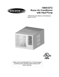
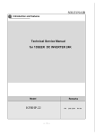
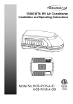
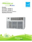
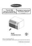
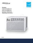
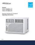
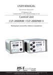
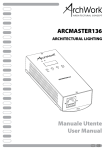
Wall Mounted Mini Split Heat Pump Air Conditioner OPERATING AND INSTALLATION MANUAL Model: KFIHP-09-ID / KFHIP-09-OD KFHHP-12-ID / KFHHP-12-OD Indoor Unit. Outdoor Unit. Thank you for selecting Soleus Air. To ensure proper operation, please read this manual and keep it for future reference. TABLE OF CONTENTS STRUCTURE AND OPERATION...……………………..……………………………………….....1-8 Name of Each Part…………………………………………………………….………..………...……1 The Instructions before Use…………………………………………………………………………2-3 Specifications and Technical Data……………………………….……..……………….…………….4 Remote Control Operation………………………………………………….….…...............………5-6 How to Insert Batteries……………………………………………..………………….………...……7 Operation………………………………………………………………………………………...……8 INSTALLATION...……………………..……………………………………………………...........9-14 Installation Location………………………………………………….………………………………9 Electric Wiring………………………………………....………………………………...….……….10 Grounding Requirement…………………………………………………….…...……..………....….10 Installation Dimension Diagram……………………………………………………….…….………11 Installation…………………………………………………………………………….……….....12-13 Install the Indoor Unit…………………………………………………………………………….....14 Install the Outdoor Unit……………………………………………………………………...…..15-16 Test Operation and Check after Installation……………………………….………………………...17 CARE AND MAINTENANCE……………………………………………...………..…….……...…18 Care and Maintenance ………………………………………………………....………….…….18-19 Trouble Shooting………………………………….………………………………………..……20-21 ELECTRICAL SCHEMATIC DIAGRAM…………………………………...………..…………22-23 Electrical Schematic Diagram (Indoor Unit)…………………………...……………......………….22 Electrical Schematic Diagram (Outdoor Unit)………..……………………….……………………23 WARRANTY…………………………………………………………………………………………24 Danger Caution. This mark indicates a direction/procedure that must be followed! Thank you for selecting Soleus Air. To ensure proper operation, please read this manual and keep it for future reference. Structure and Operation ◆Name of Each Part -1- ◆The Instructions before Use Warning ★Grounding: The unit must be properly grounded. ★Disconnect the power when the unit is not being used for extended periods of time. ★Don’t attempt to repair the air conditioner by yourself. There are no user replaceable parts. Please contact your authorized dealer. ★If your air conditioner malfunctions, ★Never block the air inlet or outlet of indoor and outdoor unit. ★Don’t step on the top of the outdoor unit or ★Never store flammable liquids near your air conditioner. ★The condensing unit should be securely mounted to avoid damage. discontinue use and call your authorized dealer. place something on it. -2- ◆The Instructions before Use ★Set the room temperature appropriately. ★Adjust the air flow and direction properly. When the air conditioner is running, you can press the SWING key on the remote control to adjust the guide louver and change the direction of air flow. The difference between indoor and outdoor temperature shall be 40 °F. ★Close all doors & windows for efficient ★To avoid harm to your pets or plants, never operation. direct the airflow at them. ★To avoid damage or electric shock, never spray liquid onto the unit. ★This air conditioner cannot be used for drying clothes or refrigerating foods. -3- ◆Specification and Technical Data KFIHP-09-ID KFIHP-09-OD Model KFHHP-12-ID KFHHP-12-OD Function Cool / Heat Accessory Air Cleaner Cooling capacity (Btu/h) 9000 12000 Heating capacity (Btu/h) 9500 13000 115V~ 208~230 Power Supply (V) Frequency (Hz) 60 Cooling/Heating rated current(A) 12/13.6 9/10 Cooling/Heating rated power(W) 1250/1450 1700/1750 Cooling/Heating power input(W) 730/840 1100/1200 Recycling air Volume(m3/h) 550 Refrigerant and weight(lbs) R410A 2.6 lbs R410A Water proof level IP24 Noise(Indoor/Outdoor)dB(A) 43/55 Climate type 2.8 lbs T1 Anti-electric shock protection I Weight Indoor/Outdoor)(lbs) Dimensions Indoor unit (W x D x H) Outdoor unit 24.3/99.2 24.3/99.2 30.31”×7.48”×9.84” 32.68”×8.86”×11.22” 33.39”×12.6”×21.26” 33.39”×12.6”×21.26” Connection Pipe: Length (ft) Gas additional charge(oz/ft) Outer Diameter Max Distance 19.68 0.16 Φ6(1/4”) Φ12(1/2”) 16.4 49.21 Liquid Pipe (mm) Gas Pipe (mm) Height (ft) Length (ft) 1. 2. All above are tested and certified to ETL specification. All above could be changed without notice; the latest specifications are on the nameplate of your air conditioner. 3. When the unit is restarted after it stopping, it can automatically resume the last running mode, and the outdoor unit starts later. Working temperature range: Maximum cooling Minimum cooling Maximum heating Minimum heating Indoor side DB/WB(°F) Outdoor side DB/WB(°F) 89.6 / 73.4 69.8 / 59 80.6 / 68 / - 109.4 / 78.8 69.8 / 75.2 / 64.4 23 / 21.2 -4- ◆Remote Control Operation Function-Remote control Note: • • • Don't drop the remote control. Don't place the remote control in a location exposed to direct sunlight. When the unit is restarted after stopped, it will automatically resume its last running mode, and the outdoor unit will start there after. MODE Button: TEMP+ TEMP- Button: When the unit is turned on, press this button. The AUTO, COOL, DRY, FAN or HEAT mode can then be selected. Under the COOL, DRY, FAN or HEAT mode, press these two buttons could set the temperature, the temp. setting range is 60.8°F -86°F, the temp. can be memorized under each mode. FAN SPEED Button: When the unit starts up, under the AUTO, COOL, FAN or HEAT mode, press this button and select Auto fan, Low fan, Middle fan, High fan. At DRY mode, the fan speed runs at Low fan speed. The FAN SPEED can be memorized under various modes. CLOCK Button: When pressing this button once, the icon of CLOCK will flash, and can be adjusted. At CLOCK adjustment, press the TIME+ once, the ones placed on the minute will be increased 1, and continuously press 1 sec above, the tens place on the minute will be increased 1 in every half second. When pressing the TIME-, the ones placed on the minute will be decreased 1, and continuously press 1 sec above, the tens place will be decreased 1 in every half second. After adjusting please press the CLOCK button again for confirming. SLEEP Button: Under COOL, DRY & HEAT mode, press the button once to start the SLEEP function, when pressed again, it will stop. -5- ◆Remote Control Operation (Continued) Liquid Crystal Display. It shows all set contents. ON/OFF Button SWING Button: Press ON. Press OFF. Press once to have louvers swing [oscillate]. Press twice in one second the panel light will turn on. Press twice again and the light will turn off. T-ON Button. When pressing this button once, enter into T-ON setting, the icon of T-ON flash, every press of TIME+, the time of T-ON will be increased 1min. When continuously press 1 sec above, the tens placed on minute will be increased 1, every press of TIME- will be decreased 1 minute, when continuously press 1 sec above, the tens placed on minute will be decrease 1 in every half second, and it goes round with 12 hours. T-OFF Button Press this button once to enter into T-OFF setting, the icon of TOFF will flash, the TOFF button is available in ON or OFF mode, the setting method is the same with T-ON. CANCEL Button Pressing this button will cancel timer. TIME+ TIME- Button Function instruction please refer to T-ON button, TOFF button, CLOCK button. -6- ◆How to Insert Batteries 1. Remove the cover from the back of the remote control. 2. Insert the two batteries (Two AAA dry-cell batteries). 3. Re-attach the cover. NOTE: • • • • Don’t mix different batteries. Remove batteries when not in use for a longtime. The batteries can be used for about one year. Keep remote at least 3.28 feet from TV’s and other electronic devices. When the wireless remote control is lost or broken, please use the manual switch, It will start in AUTO mode, the temperature setting and fan speed cannot be changed. Please use a ball point pen or similar device to operate switch. • Turn on the unit: By pressing the Manual Switch the unit will start in AUTO automatically. The microcomputer will adjust to the indoor temperature by selecting (COOL, HEAT, FAN), in order to achieve a comfortable condition. Turn off the unit: When unit is running, press the manual switch STOP button, the unit will stop running. -7- ◆Operation The general procedure: 1. Power the unit and a buzzer will sound. Power/Run indication is red and the air conditioner is waiting to run. (Note: Once the air conditioner plugs to power supply or receives the signal of remote control, the buzzer will send out the desirable sound.) 2. Press ON/OFF button, Power/Run indication is green and shows the running mode (Cooling, Heating, and Auto), and then the air conditioner starts running. 3. Press MODE button to select desired running mode. 4. Press SWING button to automatically swing and stop when repress it. 5. Press FAN button to set desired fan speed. 6. Press TEMP. button to set desired temperature. Procedure for SLEEP mode: 7. Press SLEEP button to set the sleep. 8. Press TIMER button to set the present ON TIME or OFF TIME. Note: In AUTO mode, the unit will automatically adjust its running modes according to the room temperature changes. -8- Installation ◆Installation Location Indoor Unit 1. The inlet and outlet should not be covered so that the outflow air can reach all parts of the room. 2. Install in a location from which the condensation water can be drained out conveniently and that is permitting easy connection with the outdoor unit. 3. Avoid a location where there is heat source, steam or inflammable gas. 4. Install in a location where it can withstand the full weight and vibration of the unit. 5. Be sure to leave enough space to allow access for routine maintenance. The height of the installation should be 7.55 feet or more away from the floor. 6. Install in a location where it is 3.28 feet or more away from other electric appliances such as television, audio devices, etc. 7. Select a location where it is easy to remove and clean the filter. 8. Be sure that the installation conforms to the installation dimension diagram. 9. The plug should be accessible after the appliance is positioned. Outdoor Unit 10. 11. 12. 13. Select a location from which noise and outflow air emitted by unit will not inconvenience neighbors. Select a location where there should be sufficient ventilation. The inlet and outlet should not be covered. The location should be able to withstand the full weight and vibration of the outdoor unit and permit safe installation. 14. There should be no danger of flammable gas or corrosive gas leaks. 15. Be sure that the installation conforms to the installation dimension diagram. -9- ◆Electric Wiring 1. 2. 3. 4. All the electric work must be done according to the wiring diagram. Check for the correct voltage of the unit. Don’t pull the power cord strongly. The air conditioner must be safely grounded! Grounding wire must be connected to the building and done by the qualified personnel. In fixed circuit, there must be electricity leakage protection switch of enough power capacity and air switch with enough space. Air switch (thermal-magnetic breaker) can protect the short circuit and over load. ◆Grounding Requirement 1. The air conditioner is class 1 appliance, so it must connect with ground reliably. 2. The yellow-green wires in the air conditioner are grounding wires and can’t be used for other purposes. 3. The grounding-resistance should conform to the requirement of IEC Standard. - 10 - ◆Installation Dimension Diagram Important Notes The installation must be done by trained and qualified service personnel. 112.6 inch 212.6 inch - 11 - ◆Installation • Install the rear panel 1. Always mount the rear panel horizontally. Because the mouth of drainage pipe is at the left side and the left side of the rear panel is better to adjust slightly lower. 2. Fix the rear panel on the selected location with screws supplied with the unit. 3. Be sure that the rear panel has been fixed firmly enough to withstand the weight of an adult of 132.3 lbs; furthermore, the weight should be evenly shared by each screw. 50 50 • Install the piping hole 1. Make the piping hole (Φ50) in the wall at a slight downward slant to the out door side. (Shown in Fig. 1) 2. Insert the piping-hole sleeve into the hole to prevent the connection piping and wiring from being damaged when passing through the hole. • Install the drainage hose 1. For well draining, the drain hose should be placed at a downward slant. 2. Do not wrench or bend the drain hose or flood its end by water. 3. The extended drainage pipe in the room should be wrapped with the insulating materials. • Install the connection pipes Connect the connection pipes with the relevant union pipes of the indoor unit and tighten the flare nut of the connection pipes (Shown in P16 “Install the connection pipes”). NOTE: 1. Connect the connection pipes with the indoor unit first and the outdoor unit second. 2. Be careful in bending the connection pipes, or you will damage the pipes. 3. Do not over tighten the flare nut. There is a possibility of leakage. • Electric wiring 1. Open the surface panel. 2. Remove the fixed screw from the wiring cover as shown at the right side. 3. Route the power connection cord from the back of the indoor unit and pull it toward the front through the wiring hole for connection. - 12 - ◆Installation 4. Connect the Neutral wire of the power connection cables to the “N (1)” terminal of the terminal board, connect the Signal wire to the “2” terminal, and connect the live wire to the“3”terminal and connect the grounding wire to the “ ” terminal. 5. Reassemble the wiring cover and tighten the screw. 6. Recover the surface panel. - 13 - ◆ Install the Indoor Unit 1. When routing the piping and wiring from the left or right side of the indoor unit, cut off the tailings from the chassis in necessary (shown in Fig.4 (a), (b) and (c)). (1) Cut off the tailings 1 when routing the wiring only. (2) Cut off the tailings 1 and tailings 2 (or tailings 1, tailings 2 and tailings 3) when routing both the wiring and piping. ①, ②, and ③ in Fig. 4 are the recommended piping. 2. Wrap the piping and wiring and pull them through the cut-off-tailings hole (Shown in Fig.5). 3. Hang the mounting slots of the indoor unit on the upper tabs of the rear panel and check if it is secured. 4. The height of the installed location should be 6.56 feet or more from the floor. - 14 - ◆Install the Outdoor Unit • Install the connection pipe 1. Align the center of the piping flare with the valve. 2. Screw in the flare nut by hand and then tighten the nut with spanner and torque wrench refer to right figure. Tightening Torque Table Hex Nut Diameter (mm) Φ6 φ12 Tightening Torque (N.m) 15~20 50~55 Note: Exceeding tightening torque will damage the flare nut. • Electric wiring connection 1. Disassemble the big handle. 2. Remove the wire clamp and connect the end of the power connection cord with screws to the wiring terminal board. Be sure that the wiring connection is in accordance with the indoor unit’s. 3. Fix the wiring with wire clamp. For the heat pump join the two control cords. 4. Make sure that the wiring has been connected securely. 5. Reassemble the big handle. NOTE: 1. Incorrect wiring connections will cause electrical malfunction. 2. Do not pull the wire when assembling it with wire clamp. - 15 - ◆Install the Outdoor Unit • Air Purging and Leakage Test 1. Remove the flare nuts of charging end from gas valve. 2. Connect the charging hose in the middle to the vacuum pump, then Low-pressure (Lo) end should be connected to charging end of gas valve. (Shown in Fig. 9) 3. Open the vacuum pump to evacuate. When multi-meter indicates 1 bar, fully tighten Lo handle of manifold valve and stop evacuation. Keep it for over 15 minutes to ensure the pressure is constant. 4. Remove bonnets of gas and liquid valve. 5. Slightly loosen core of liquid valve with hexagon wrench until the pressure exceeds 0 bars. 6. Remove charging hose from charging end of gas valve and screw the flare nuts of charging end. 7. Open cores of gas and liquid valve entirely by hexagon wrench. 8. Tighten the bonnets of gas and liquid valve, and then test whether there is any leakage or not. - 16 - ◆Test Operation and Check after Installation Test Operation 1. Before Test Operation (1) Do not switch on power before installation is finished completely. (2) Electric wiring must be connected correctly and securely (3) Cut-off valves of the connection pipes should be opened. (4) All the impurities such as scraps must be cleared from the unit. 2. Test Operation Method (1) Switch on power and press “ON/OFF” button on the remote control to run the air conditioner. (2) Press “MODE” button and check the operation condition of COOL, HEAT, SWING mode and so on. If Wireless remote control is lost, open the surface panel and operate as following: a. When turning it to Auto position, unit will run in Auto mode, if there is remote control signal, it will run at the remote control signal. b. When turning it to Test position, the main unit will enter into Cool mode, indoor fan will run at high fan speed, if there is remote control signal, main unit will run at the remote control signal. c. When turning it to Run position, the main unit will run at received remote control order. d. When turning it to Stop position, the unit will stop running. Check after Installation Items to be checked Possible Malfunction Has it been properly mounted? The unit may drop, shake or emit noise. Have you done the refrigerant leakage test? It may cause insufficient cooling (heating) capacity. Does the unit drain well? Is the voltage in accordance with the rated voltage marked on the nameplate? Is the electric wiring and piping connection installed correctly and securely? Has the unit been connected to secure grounding connection? Has the inlet and outlet been insulated? Has the length of connection pipes and refrigerant capacity been recorded? It may cause condensation and dripping. It may cause electric malfunction or damage the part. It may cause electric malfunction or damage the unit. It may cause electrical leakage. It may cause insufficient cooling (heating) capacity. The refrigerant capacity is not accurate. - 17 - Care and Maintenance ◆Care and Maintenance CAUTION: Turn power off and pull out the power cord before cleaning air conditioner. Never sprinkle water on the indoor unit and the outdoor unit for cleaning because it can cause an electric shock. Volatile Liquid (e.g. thinner or gasoline) will damage the air conditioner. (So wipe the units with a dry soft cloth, or a cloth slightly moistened with water or cleanser.) Clean the front panel (Don’t remove the front panel when cleaning) When the indoor unit front panel is dirty, please use the cloth which is soaked in the warm water under 104°F, then dry it and wipe the dirty places. NOTE: There are microcomputer components and circuit board on the displayer of the indoor unit front panel, never let it dip in the water. Cleaning the Air Filters (Recommended once every three months) The air filters should be cleaned more frequently in dusty conditions. 1. Take down the air filter Open the surface panel, hold the tab of air filter and raise it slightly, and then take it out along the direction of arrows (See the right figure). 2. Cleaning To clear the dust adhering to the filters, you can either use a vacuum cleaner, or wash them with water and dry it in the shade (See the right figure). Note: Never use water above 113°F to wash the filters, or it could cause deformation or discoloration. Never parch it by fire, or it could cause a fire or deformation. - 18 - ◆Care and Maintenance (Continued) 3. Reinsert the filters Reinsert the filters along the direction of arrow, then cover the surface panel and clasp it. Check before Use 1. Be sure that nothing obstructs the air outlet and intake vents. 2. Verify that the unit is properly grounded. 3. Always use new batteries. 4. Verify condenser is properly mounted. Maintain after Use 1. Clean filters and other parts. 2. Turn main power off. 3. Clean dust from the outdoor unit. ◆Trouble Shooting Warning: Don’t attempt to repair the air conditioner by yourself; it can cause an electric shock or fire. Please check the following items before calling your service technician. Problem Trouble Shooting Won’t start immediately when the air conditioner is restarted. Once the air conditioner is stopped, it will not operate until the time delay of 3 minutes has passed. There’s unusual odor blowing from the outlet after operation is started. - 19 - This is caused by the odors in the room. ◆Trouble Shooting Problem Trouble Shooting Sound of water flow can be heard during operation. This is caused by the refrigerant flowing inside the unit. Mist is emitted during cooling operation. Because the air of the room is cooled down rapidly. Creaking noise can be heard when start or stop the unit. This is caused by the expansion of plastic due to the change of temperature. Air conditioner does not operate at all. • Has the power been shut down? • Is the wiring loose? • Is the leakage protection switch in operation? • Is TIMER ON is operation? Cooling (Heating) efficiency is not good. • • • • • • Is SET TEMP. suitable? Is air inlet or outlet obstructed? Are air filters dirty? Are the windows and door closed? Is indoor fan speed set at low speed? Is there any other hear source in your room? • Remote control can’t be used when the air conditioner is disturbed or changing its functions frequently. • Is the remote control out of effective to the indoor unit? Are there any obstruction between the remote control and the signal receptor? • Replace the worn batteries of remote control is the voltage of the batteries is not sufficient. Remote control is not operating - 20 - ◆Trouble Shooting Immediately discontinue using the unit and disconnect the power if any of the following occurs: Unusual noise can be heard during operation. Air switch or leakage protection switch often shuts down. Water is leaking from the unit. Electrical lines and power plug are very hot or smoking. Wind blowing from the outlet smells terrible during operation. - 21 - If you have any question, please call your contractor or service dept. Electrical Schematic Diagram ◆Electrical Schematic Diagram (Indoor Unit) Please Insert Diagram in here. - 22 - ◆Electrical Schematic Diagram (Outdoor Unit) Please Insert Diagram in here. - 23 - Warranty Soleus International Inc. warrants the accompanying Soleus Air Wall Mounted Mini Split Heat Pump Air Conditioner (KFIHP-09-ID/KFIHP-09-OD; KFHHP-12-ID/KFHHP-12-OD) to be free of defects in material and workmanship for the applications specified in its operation instruction for the period of labor and parts specified below. 5 YEARS FOR COMPRESSOR 1 YEAR FOR OTHER COMPONENTS This warranty shall not apply to broken or marred cabinets, accessories, knobs, filters or routine maintenance. This warranty does not apply to uncrating, setup, installation, removal of the product for repair or reinstallation of the product after repair. This warranty does not apply to repairs or replacements necessitated by any cause beyond the control of Soleus International including, but not limited to, any malfunction, defect or failure caused by or resulting from unauthorized service or parts, improper maintenance, operation contrary to furnished instructions, shipping or transit accidents, modification or repair by the user, abuse, misuse, neglect, accident, incorrect power line voltage, fire, flood or other Acts of God, or normal wear and tear. Warranty service must be performed by a qualified HVAC contractor. Soleus maintains a centralized service network to provide parts and assist in resolving service problems if difficulties are encountered. Soleus agrees to provide service information, sell repair parts and reimburse the dealer /servicer for parts and services in accordance with Soleus International’s Policies and Procedures. SOLEUS INTERNATIONAL MAINTAINS THAT ALL WARRANTIES, INCLUDING IMPLIED WARRANTY OR MERCHANTABILITY ARE LIMITED TO THE TERMS AND CONDITIONS SPECIFIED ABOVE. SOLEUS INTERNATIONAL DISCLAIMS ANY LIBILITY FOR CONSEQUENTIAL OR INCIDENTAL DAMAGES AND IN NO EVENT SHALL SOLEUS INTERNATIONAL INC.’S LIABILITY EXCEED THE RETAIL VALUE OF THE AIR CONDITIONER. This warranty covers only new products purchased from our authorized dealers or retailers. It does not cover used, internet sales, salvaged, or refurbished products. FOR TECHNICAL SUPPORT AND WARRANTY SERVICE Soleus International Inc. Tel: 1-888-8 SOLEUS Monday through Friday, 9:00 AM to 5:00 PM, PST Email: [email protected] Website: www.soleusair.com - 24 -